
Abstract
In view of the control effects of fluidic thrust vector technology for low-speed aircraft at high altitude/low density and low altitude/high density are studied. The S-A model of FLUENT software is used to simulate the flow field inside and outside the nozzle with variable control surface parameters, and the relationship between the area of control surface and the deflection effect of main flow at different altitudes is obtained. It is found that the fluidic thrust vectoring nozzle can effectively control the internal flow in the ground state and the high altitude/low density state. and the mainstream deflection angle can be continuously adjusted. The maximum deflection angle of the flow in the ground state is 21.86°, and the maximum deviation angle of the 20 km high altitude/low density state is 18.80°. The deflecting of the inner flow of the nozzle is beneficial to provide more lateral force and lateral torque for the aircraft. The high altitude/low density state is taken as an example. When the internal flow deflects 18.80°, the lateral force is 0.32 times the main thrust. For aircraft with high altitude and low density, sufficient lateral and lateral torque can make the flying aircraft more flexible, which can make up the shortcomings of the conventional rudder failure and even replace the conventional rudder surface.
Keywords
Introduction
Thrust vector technology brings many advantages to modern aircraft, making it a key essential technology.1–3 Thrust vector technology is an important way to improve the high maneuverability of aircraft. The thrust is deflected by the thrust vectoring nozzle, and the required control torque is obtained.4,5 At present, the thrust vectoring nozzles are mainly composed of mechanical controlled nozzles. After the mechanical thrust vectoring nozzle is used in aircraft, many characteristics have been improved to varying degrees and great engineering benefits have been obtained.6,7 The mechanical thrust vectoring nozzle realizes the main jet deflection by directly changing the mechanical structure of the nozzle. Although it has been used in the model, there are still many problems and deficiencies. The mass is heavy: the mechanical thrust vectoring nozzle not only has high temperature resistance and high mechanical strength, but also causes heavy weight of the engine tail nozzle, usually it can increase the weight 20%–30% of the engine,8,9 the reliability is poor and the life of the nozzle is short: the mechanical thrust vectoring nozzle has a complex structure and many moving parts, so its reliability is greatly improved. Lower and shorter service life. The thrust loss of the engine is serious: when the nozzle is deflected by the mechanical thrust vector nozzle, the thrust loss can reach more than 10%, and the thrust loss is serious. 10 Compared with mechanical thrust vector control, fluid thrust vector control has its own unique advantages. The structure of fluidic thrust vectoring nozzle is simple, only need few actuating components, few air source facilities, and ventilation pipes. Fluidic thrust vectoring control technology will soon become a new direction of thrust vector technology development.11,12
According to the generation principle of thrust vector, the realization forms of fluid thrust vector control technology can be roughly divided into five basic types: shock vector fluid thrust vector control, Throat Skewing fluid thrust vector control, counter-flow fluid thrust vector control, Co-flow fluid thrust vector control and Coanda effect fluid thrust vector control.7,8,12–15 The shock vector control is to introduce a secondary jet into one side of the nozzle expansion section, and generate oblique shock when the high-speed main stream flows through it, so as to change the direction of the main stream to obtain the required vector angle. Zhang et al. 16 of Northwestern University of technology carried out relevant research by means of numerical simulation. In this study, the maximum vector deflection angle is 17° and the thrust coefficient is 0.92–0.97. The Throat Skewing fluid thrust vector control is to control the throat area of the nozzle. The high-speed jet secondary flow is vertically introduced into the throat of the nozzle to make the secondary flow interact with the main jet so as to change the throat shape and flow area of the main jet, and then realize the throat adjustment and thrust vector control. However, this implementation has the disadvantage of low efficiency of thrust vector. In 1999, Lockheed Martin company’s relevant personnel used the fluid throat offset scheme to control the thrust vector deflection of the fixed shape expansion nozzle, studied the control ability of the scheme to the thrust vector deflection, and evaluated the total thrust loss. 17 The counter-flow fluid thrust vector control is to add a solid wall on the outer surface of the main nozzle to form a secondary flow channel in the sandwich space. When it is necessary to control the main jet of the nozzle, the reverse secondary flow is generated in the cavity. The pressure distribution at the exit of the original nozzle is not uniform, and the main flow deflects to the secondary flow direction. However, the main problem of the reverse flow vector control is that the main flow may not be separated from the wall easily (with serious hysteresis), which will weaken the efficiency of the thrust vector control to a large extent. Wu et al. 15 conducted on the supersonic nozzle to investigate the possibility of utilizing counter-flow in fluidic thrust vector control. The co-flow fluid thrust vector control is to inject the secondary flow in the same direction as the main jet, and make use of Coanda wall effect to generate thrust vector of the main jet. Coanda effect refers to that when the fluid (flow or airflow) flows through the convex fluid surface, the pressure near the wall decreases due to the effect of eddy current, so the fluid has a trend of leaving the original flow direction and flowing with the wall. When the main jet is a subsonic flow, the same direction flow technology can obtain better thrust vector performance. Because the secondary flow and the main jet are in the same direction, the thrust can also be generated, which improves the thrust efficiency of the nozzle. The loss of 1% of the main flow can make the main flow deflect 1.8∼2.4° and the thrust coefficient as high as 0.98. However, one of the disadvantages of co-flow control technology is that the control efficiency of the main jet with high Mach number will decrease obviously. Sóbester and Keane 18 of the University of Southampton, UK, used numerical simulation to carry out multi-objective optimization design of the same flow thrust vectoring nozzle model. The optimization algorithm and model are designed to minimize the thrust loss and outlet pressure fluctuation. Wilde and Crowther 19 of the University of Manchester in England designed two kinds of vectoring nozzles based on the same direction flow control and performed in wind tunnel. The vector angles of 3.4° and 9.6° are obtained when the secondary flow consumption is 10% of the main flow. Heo et al. 12 of Korea University of Astronautics studied the thrust vector deflection performance of supersonic nozzle under the same direction flow control by means of numerical calculation and experiment, and analyzed the response time influence of the injection amount of control flow on jet deflection and the pressure distribution on nozzle wall. Passive Coanda secondary flow control. The main purpose is to reduce the consumption of secondary flow and find the method of vector continuous control. The idea of jet deflection control: the pressure in the low-pressure area can be restored by opening the nozzle wall at the root, then the pressure in the area can be changed. By controlling the size of the root opening, that is, the size of the channel around which the fluid is replenished, the pressure in the low-pressure area of the root area can be controlled. By controlling the inlet area on both sides, the pressure difference will be generated in the low pressure area on both sides of the jet, which will deflect the jet. Controlling the pressure difference between the low pressure areas on both sides of the jet can control the deflection angle of the jet. 22
Counter-flow control and co-flow control are two efficient and feasible fluid type thrust vector technologies, which have great development and application prospects. The passive fluid thrust vector technology does not need external gas source, avoids the complicated gas pipeline layout, improves the main jet deflection response efficiency, reduces the secondary flow injection energy consumption, and has higher application feasibility. For passive secondary flow control. Around 2019, Cao et al. 20 and Zhao 21 of Nanjing University of Aeronautics and Astronautics carried out experimental research on the high-speed passive thrust vectoring nozzle, and achieved great research results. However, the characteristics of passive Coanda secondary flow fluidic thrust vector technology control under high altitude, low density, and low speed flight conditions have not been studied. The conventional rudder control efficiency is low under high altitude, low density, and low speed flight conditions. In this paper, a new type of nozzle is designed, its structure is novel, the nozzle can carry on the control of the thrust vectoring deflection with gas. The characteristics of high altitude, low density, and low speed flight conditions are studied, which provides a new method for the control of high altitude, low density, and low speed aircraft.
Nozzle model
The two-dimensional model of the fluidic thrust vectoring nozzle in this paper is shown in Figure 1, and the half module of the nozzle is shown in Figure 2. The air flow at the nozzle is divided into internal flow and outflow. The internal flow reaches the upper and lower control joints after contracting the throat.

Two dimensional parameter diagram of nozzle.

Nozzle detail diagram.
The throat height of the throat of fluidic thrust vectoring nozzle is 10 mm, and a control seam with a width of 1.4 mm is arranged at the upper and lower sides of the throat. The direction of the control seam exit and the main flow direction are 30°. The control seam extends from the catheter to the outer wall of the nozzle. The expansion section consists of two straight segments, 12° and 24° respectively. The nozzle width is 40 mm and throat width to height ratio is 4:1. The front part of the nozzle is the contraction of 2:1.
Numerical simulation parameters
Grid parameters
Figure 3 is a model grid diagram. In this paper, we use a relatively simple commercial software to complete the grid. As shown in Figure 3. According to simulation experience, for turbulence modeling, to get enough accuracy, the dimensionless variables y+ for the height of the first boundary layer should around.22–24 In our study, we set y+ = 0.5. To reduce numerical dissipation due to grids, we smooth the grids by limiting growth rate of grid height to 1.15. The height of the outflow on both sides of the model is equal to the height of 20 mm at the entrance of the inner flow. Each side of the model entrance is divided into 50 nodes, the nodes are evenly distributed, the distance between each node is 0.4 mm, the inner flow part is divided by the structural grid, while the other irregular areas are used in the unstructured grid. There are 465,000 grids in the flow area, 228,000 in the intersection of internal flow and outflow, and the number of the whole model grid is 1 million 64 thousand. It can be seen that the grid of the intersection of the flow and the outflow is encrypted. The boundary conditions of each wall surface of the model are set as non-penetrating objects, the internal and external flows are set as velocity inlets, and the semi-cylindrical flow outlets are set as pressure outlets.

Model grid.
The internal flow and both sides of the flow are connected by the vent and control seam. Because the model is completely symmetrical up and down, the whole state can be simulated only by selecting one side of the vent as the control mouth. Figure 3 shows the lower side port is the model control port, the upper side vent is not controlled, and is completely open. The control ring is formed by the size of the control ring which is smaller than the original one, and the size of the control ring indicates the size of the closed area of the control mouth.
Model boundary condition
In this paper, the boundary conditions of nozzle initial parameters, internal flow and outflow velocity are set according to the ground state and altitude 20 km state. By changing the area of the control ring, this paper changes the pressure difference at both sides of the control joint, and realizes the deflection of different angles of the internal flow, thus providing the lateral force and torque for the aircraft.
Symbol description: H indicates 20 km high altitude low density state; L indicates ground state;
Ground state
This paper uses FLUENT software to carry out numerical simulation. Fluent software is recognized worldwide as a numerical simulation software. It is often used for numerical simulation of various complex flow fields. The solver of the ground incompressible state is a Pressure Based solver based on pressure, and the viscous model is a Spalart-Allmaras one-equation turbulence model (S-A model). Spalart-Allmaras one-equation turbulence model can accurately predic flows with adverse pressure-gradients.22,25 It is also robust and requires only moderate grid resolution in the near-wall region.26,27 Therefore, S-A model has been widely used in engineering computations. The convergence accuracy of the calculated residual is 10−5.
High altitude 20 km state
20 km the upper air speed
Data analysis
Uncontrolled state
The upper and lower control ports are closed to uncontrolled state at the same time.
Uncontrolled ground state
As can be seen from Figure 4, the inner wall pressure curve of the ground state model is completely reclosing with no control, and the flow field is also symmetrical, and the internal flow angle is 0.

The internal pressure curve and streamline of the symmetrical surface of the ground state without control model: (a)
Uncontrolled high altitude state
The pressure curve of the inner wall is completely overlapped when the altitude state model is not controlled from Figure 5, the flow field is also up and down, and the internal flow angle is 0.

Internal pressure curve and streamline of symmetrical surface in high altitude state without control model: (a)
Control results after application of control
Ground state
The flow state of the ground state is as follows:

The internal pressure curve and streamline of symmetrical surface of the model with different ground state
From the pressure curve of the inner wall of each model, it can be seen that with the
Figure 7 is a corresponding diagram of the upper and lower wall pressure curves and the location of the model under the condition of complete control (

The relationship between the surface pressure and the location of the ground state model surface in the
The pressure curve of the inner flow wall can be divided into many segments, and the special points in the diagram are expressed in letters. The control curve corresponds to the lower wall of the flow field, and the non-control curve corresponds to the upper wall of the flow field. The main aerodynamic characteristics of the model are briefly explained below.
In the a∼b: ab section, the pressure coefficient decreases with the influence of the low pressure of the control joints. The b∼c:c point is located at the junction of the internal flow and the control joint. The phase loss of airflow causes the loss of kinetic energy and the increase of static pressure. There is no data in the c∼d:cd section, which indicates that the control section is not the wall, so there is no pressure data. Point d is located below point c, at the bottom of the step, unaffected by the air flow, so the pressure is much lower than point c. Because of the large volume of blind holes in the lower left of point d, the suction of air flow is more obvious, which makes the pressure of point d lower. The d∼e: e point is located in the separation bubble of the control seams, where the pressure coefficient is the lowest. e∼f: slowly away from the control joint, the wall pressure coefficient increases slowly. f∼g: from the streamline diagram, we can see that g represents the inflection point of the model 12° to 24°, and the decrease of fg pressure may be due to the sudden change of pressure caused by the airflow through the turning point; g∼h:h is indicated as the tail of the nozzle, which is close to the external flow field and its hydrostatic pressure is close to 0. The a∼i: a point speed is high, the pressure coefficient is relatively low, and the pressure coefficient is close to 0 at I through the air outlet and the external flow field. The i∼j: ij segment also has no data to indicate the control joints. The j∼h: j point is connected with the outside, but it is located inside the nozzle, so the pressure coefficient is slightly lower than the outside.
High altitude 20 km state
The flow field at high altitude and low density is as follows:
Figure 8 is the pressure curve and streamline diagram of the symmetrical inner wall of the model in the state of high altitude and low density. Similar to Figure 6, a conclusion similar to that of Figure 6 can be drawn. With the increase of the

Internal pressure curves and streamlines of symmetric surfaces in different 20 km S models.
Thus, we know that the increase of the area of control ring at high altitude and low density can also effectively control the deflections of the model internal flow, which is beneficial to the lateral and lateral torque for high altitude/low density aircraft. At the same time, the minimum pressure coefficient of high altitude/low density control state is −0.4, and the minimum pressure coefficient of ground fully controlled state is −0.64.
Figure 9 is a correspondence diagram of the flow wall pressure curve and the model in the fully controlled model under the condition of high altitude and low density. The pressure curve of the inner flow wall can be divided into many sections. The position of the letter point in the Figure 9 is the same as that in Figure 7. The control curve corresponds to the lower wall of the flow field, and the non control curve corresponds to the upper wall of the flow field.

The upper air 20 km state, the corresponding relationship between the wall pressure and the model position of the symmetric surface of the
The A∼B∼C:ABC section is affected by the low pressure of the control joints, and the pressure coefficient gradually decreases. Different from the ground state, there is not a small increase in the BC segment. There is no data in the C∼D:CD section, which indicates that the control section is not the wall, so there is no pressure data. D∼E∼F∼G∼H: slowly away from the control joint, the wall pressure coefficient increases slowly. It can be seen from this diagram that the pressure changes on this wall are smooth and without step points. The A∼I: A point speed is high, the pressure coefficient is relatively low, and the pressure coefficient is close to 0 at I through the air outlet and the external flow field. The I∼J: IJ segment also has no data to indicate the control joints. J∼H: J is connected to the outside, but it is located inside the nozzle, it will not be affected by the external air flow, so the pressure coefficient is slightly lower than the outside.
Comparison of ground state and high altitude 20 km state
The variation curve of θ with the ΔS
It can be seen from the diagram that the internal flow angle theta of the ground state and the high altitude low density state model increases with the increase of the area of the control ring area
High altitude low density state:
Origin ∼A: in the slow growth stage, the declination theta increases proportions with the increase of the control ring area S. A∼B: in the sensitive stage, the declination theta increases rapidly with the slow increase of the control ring area S. B∼C: in the insensitive stage, the declination theta does not change with the increase of the area S of the control ring after the control area exceeds the sensitive area. C∼D: sensitive stage; D∼E: the same insensitive phase.
Ground state:
Origin ∼a: As shown in Figure 10 in the slow growth stage, the declination theta increases proportions with the increase of the control ring area S. a∼b: in the sensitive stage, the declination theta increases rapidly with the slow increase of the control ring area S. b∼c: in the insensitive stage, the declination theta does not change with the increase of the area S of the control ring after the control area exceeds the sensitive area.
High altitude low density compare with ground state:
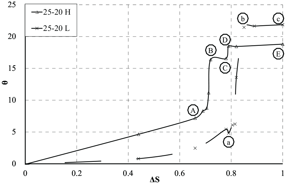
The variation curve of the internal flow angle with the area of the control ring.
With the increase of the area of the control ring, the flow in the high altitude low density state is more easily deflected than that in the ground state, and the high altitude low density state is more likely to reach the sensitive area than the ground state. But the maximum declination of ground state is about 3.5° higher than that of high altitude and low density.
The variation curve of ΔCp with ΔS
As shown in Figure 11 in the pressure difference on both sides of the control seam determines the deflection direction of the internal flow, so the delta
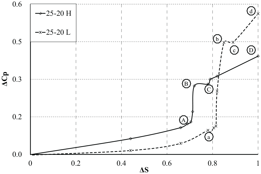
Curves of pressure difference at two control joints with the area of control loops.
The variation curve of θ with the ΔCp
It is shown from the Figure 12 that the internal flow angle theta is approximately proportional to the pressure difference between the control gap and
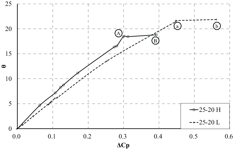
The variation curve of the pressure difference between the internal flow deflection angle and the control joint.
Conclusion
In this paper, the control effects of fluidic thrust vector technology for low-speed aircraft at high altitude/low density and low altitude/high density are studied. The results show that the fluidic thrust vectoring nozzle can effectively control the internal flow in the ground state and the high altitude/low density state. The maximum deflection angle of the flow in the ground state is 21.86°, and the maximum angle of the low density in the 20 km altitude is 18.80°. The deflecting of the inner flow of the nozzle is helpful to provide more lateral force and lateral torque for the aircraft. For example, when the internal flow is deflected at 18.80°, the lateral force is 0.32 times the main thrust.
In addition, for the fluidic thrust vector control technology, the greatest improvement in this paper is to achieve the controllable adjustment of the mainstream deflection angle. This paper adopts the form of adjusting the area of the control surface to achieve the continuous and controllable adjustment of the mainstream deflection angle. For aircraft with high altitude and low density, sufficient lateral and lateral torque can make the flying aircraft more flexible, which can make up the shortcomings of the conventional rudder failure and even replace the conventional rudder surface.
Footnotes
Declaration of conflicting interests
The author(s) declared no potential conflicts of interest with respect to the research, authorship, and/or publication of this article.
Funding
The author(s) disclosed receipt of the following financial support for the research, authorship, and/or publication of this article: This research was supported by the national natural science foundation of China (No.11672134).