
Abstract
Adverse pressure gradients can cause severe flow separation within typical S-shaped inlets. This results in a total pressure distortion at the aerodynamic interface plane (AIP). The expansive bending pipe, where flow separation also occurs due to the adverse pressure gradient, is the basis for investigations into S-shaped inlets. In this study, surface dielectric barrier discharge (SDBD) plasma actuators are used to moderate the total pressure distortion in the AIP of an expansive bending pipe under a 10 m/s incoming flow. Also, the influences of actuation voltage amplitude and pulsed frequency on the total pressure distortion of the AIP are investigated under two plasma actuation modes, nanosecond pulsed SDBD and alternating current (AC) SDBD. Under optimal actuation parameters, the nanosecond pulsed SDBD and the AC-SDBD can reduce the distortion index by 14.93% and 32.22%, respectively. The results demonstrate the effectiveness of SDBD plasma actuators in suppressing flow separation within expansive bending pipes.
Introduction
In aspirated propulsion systems, the inlet acts as the “respiratory tract,” and its operating characteristics have a tremendous impact on the efficiency of the engine and the working envelope. 1 With the growing stealth requirements in modern warfare technology, air inlets now possess the role of enhancing aircraft stealth. S-shaped inlets with large offsets allow radar waves to be reflected multiple times between the inner walls, weakening echoes and improving stealth performance. This approach has been widely applied in the Global Hawk and Predator C UAVs. 2 However, airflow within S-shaped inlets is subject to flow separation due to the adverse pressure gradient caused by its curved geometry. This results in a total circumferential pressure distortion in the aerodynamic interface plane (AIP) cross-section of the inlet, 3 which subsequently leads to a reduction in the effective thrust of the engine. 4 Structurally, the S-shaped inlet can be regarded as consisting of two expansive bending pipes. Besides, the flow separation that occurs in the S-shaped inlet also occurs in the bending pipe, so the latter can be used as the basis for investigating the S-shaped inlet. By evaluating the methods of suppressing flow separation in expansive bent ducts and improving total circumferential pressure distortion in the AIP cross-section, we can provide a methodological basis and technical support for suppressing flow separation in S-shaped inlets.
Michael M. Wojewodka et al. 5 used OpenFOAM to investigate the flow through the Wellborn s-duct and reported phase analysis of modes at the AIP in the public domain for the first time. In the study, the modal decomposition found that the dominant mode in the low-speed, low-pressure region of the AIP center exhibits one horizontal and two vertical shifting modes. The horizontal mode is postulated to be caused by secondary flow patterns and flow instabilities driven by secondary flow patterns and cross-stream. The two vertical modes are probably caused by the oscillating shear layer, which is related to the main separation in the s-duct. Numerous attempts have been made to suppress flow separation in S-shaped inlets. Xie et al. 6 proposed an ultra-compact serpentine inlet design method based on the vortex control principle to suppress separation by changing the low-energy flow migration path. In terms of passive flow control, the vane vortex generator is the most commonly used.7,8 Furthermore, Gissen et al. 9 investigated the vortex generator array approach in S-shaped inlets, which reduced the distortion index at the outlet section by 60% with the optimal parameter combination. In addition to the vortex generator, Sun et al. 10 used an inner bulge inside the inlet to regulate the boundary layer and suppress flow separation. These passive flow control methods have the advantages of simple construction and they do not require extra mass or energy. However, they cannot be adapted to the inlet conditions of the vehicle, and there may be a significant reduction in performance at the inlet system under off-design conditions. For vane vortex generators in particular, the convex structure can be a hindrance to daily maintenance and may even fall off under impingement, which may seriously affect the performance of the engine. 2
In contrast to passive control, active control can be adapted to the various operating conditions at the inlet and only requires a local disturbance of the flow field in the boundary layer to achieve global flow control. The most common form of active control is the micro-jet.11–13 Da et al. 14 employed micro-jets to control flow separation in the inlet and the distortion index fell by 75% compared to the baseline conditions, while consuming 0.65% of the mainstream high-pressure air. Harrison 15 investigated different micro-jet layouts, including ring circumferential, base plate axial and base plate V-layouts. It was discovered that the ring circumferential layout and the V-layout with an 80° angle were the most effective in controlling the flow. Burrows et al. 16 used a fluid oscillator to generate micro-jets at the second bend of an S-shaped inlet and effectively suppressed the separation flow, reducing the distortion index by 60%. Although micro-jets are effective in suppressing separation, they generally require additional air sources and piping. Furthermore, the interior of the air inlet also requires machining, which is difficult to carry out and adds extra weight to the vehicle. The surface dielectric barrier discharge (SDBD) plasma actuator has a simple structure, fast response speed, and no moving parts, which makes it a potential solution for numerous flow control fields. 17
R J. Durscher and S. Roy 18 used stereo particle image velocimetry to investigate the three-dimensional flow structure of two serpentine configuration DBD actuators: one constructed from patterned circular arcs and one from patterned rectangles. They noted that the effects of the serpentine configuration can be seen as a combination of the linear plasma synthetic jet actuator effect and a linear DBD actuator effect and spiral-like structures appear in the induced flow field. Further, the serpentine actuator was compared with a standard geometry actuator by Mark Riherd and S. Roy 19 through two numerical flow control cases. The result of two different applications shows that the general serpentine actuator offers greater versatility than the standard geometry. Besides, many scholars have applied spanwise plasma actuators to achieve skin-friction drag reduction in turbulent wall flows. 20 Jukes et al.21,22 used spanwise oscillation plasma actuators in a turbulent boundary layer at Re = 400 and measured a drag reduction of 45% for the oscillation period. Whalley and Choi 23 try to obtain skin-friction drag reduction in turbulent wall flows through spanwise traveling waves, which were generated by DBD plasma actuators.
However, over the past three decades, despite significant progress in research on plasma actuators, they have not been able to be used in practical flow systems. One of the reasons for this is the effect of environmental factors, such as rain, on the actuator. Therefore, it is particularly important to investigate the interaction between plasma and liquid. Many scholars have used different methods to study the reaction between the plasma–liquid interface, such as measuring the hydrated electron density at the plasma–liquid interface,24,25 the use of luminol chemiluminescence26,27 and sum-frequency generation vibrational spectroscopy.28–30 However, each of these methods has some imperfections in the study of plasma–liquid interactions. Naoki Shirai et al. used surface tension, which was measured through the dispersion relation of an acoustic capillary wave excited on the water surface, as a new indicator of plasma–liquid interfaces. In the experiment, they employed an atmospheric pressure dc glow discharge with intersecting helium flows and placed the v-shape discharge in parallel to the water surface at a vertical distance of 2–6 mm. Both the gas flow and the active plasma with the optical emission were not in contact with the water surface directly, and the water surface touched the outside regions of the active plasma and the downstream spatial afterglow. Based on this experiment, it can be seen that even in a humid environment, plasma can be generated normally with a certain distance between the active plasma and the liquid. More importantly, it proves the possibility that a plasma actuator can operate normally in an environment where rainwater exists. 31
Regarding the control of flow separation, SDBD has primarily been applied for separation flow suppression investigations on airfoils, wings and compressors.32–34 However, few investigations have been conducted on the inside of S-shaped inlets. 35
The experiments in this study are conducted with an expansive bending pipe as the object. The angle between the incoming flow and the normal to the pipe inlet section is set at 15°, which imitates the actual situation of the inlet working under a side wind incoming flow. In this study, we assess two plasma actuators, the nanosecond pulsed SDBD and the alternating current (AC)-SDBD. We verify how effectively they suppress flow separation within an expansive bending pipe and confirm their efficacy in reducing the total circumferential pressure distortion of the AIP cross-section under a side wind incoming flow. Through wind tunnel tests and pressure measurements, the baseline flow field is first derived. Next, the influence of actuation voltage and pulsed frequency on the flow control of the plasma actuators is investigated. This provides a basis for investigations into how plasma actuation improves the flow field quality of S-shaped inlets.
Experimental setup and tools
Expansive bending pipe model
As Figure 1 shows, the expansive bending pipe consists of four components. Starting at the inlet, they are respectively the bellmouth, stationary section, bending section, and measurement section. The cross-section of the pipe is an ellipse of gradually increasing area with an expansion ratio of 1:1.57. The ratio of the long axis to the short axis of the ellipse is fixed at 2:1. The central axis of the bending section is a circular arc with an angle of 45° and the curvature radius is 528 mm. The major geometrical parameters of these components are listed in Table 1, where Din1, Din2, Dout1, and Dout2 represent the lengths of the long and short axes of the elliptical section at the entrance and the exit of the pipe, respectively. Additionally, L denotes the length of the center line projection in the normal direction of the pipe entrance. The bellmouth and the stationary section are processed as a single part, while the other sections are sealed with sealing strips at the joints.

Expansive bending pipe construction.
Main parameters of the expansive bending pipe.
The measurement method used in this study is pressure measurement. On the left wall of the bending section, 37 pressure taps are configured along the center line. Figure 2 illustrates that in the measurement section, eight pressure taps are stacked on one side of the AIP cross-section, to determine the in-plane total pressure distribution. According to the principle of equal ring area distribution, each pressure rake has five pressure measurement ports except for the first rake, which has an additional probe located at the center of the ellipse. Therefore, a total of 41 pressure probes are installed in the cross-section of the AIP. Based on the total frontal area of the pressure rakes and the cross-sectional area of the AIP, the blockage coefficient is calculated to be 4.55%, which is within the acceptable range.
Distribution of total pressure probes in the AIP cross-sections. AIP: aerodynamic interface plane.
Tunnel and data acquisition system
The experiment is conducted in a low-speed backflow wind tunnel, which is used for the rectangular test section. The test section is 1 m long, 1.2 m wide, and 1 m high, while the incoming wind speed can be adjusted from 5 m/s to 75 m/s.
The relative position between the far-field incoming flow and the model is displayed in Figure 3. The far-field incoming flow velocity in front of the rectangular test section is 10 m/s, by adjusting the normal direction of the bellmouth section to make an angle of 15° with the incoming flow. To clearly show the relative geometric position of the incoming flow to the model inside the wind tunnel, the walls of the wind tunnel are made transparent in the following figure. Figure 1 (b) uses a three-dimensional perspective to show the placement of the bending pipe in the test section, while Figure 1 (c) uses a vertical view to reflect the angular relationship between the model and the incoming flow. What the authors are trying to convey is that the incoming flow velocity is 10 m/s, not the crossflow velocity. Further, by decomposing the incoming flow velocity, it can be observed that the flow velocity perpendicular to the pipe inlet is 9.66 m/s, while the crossflow velocity parallel to the inlet is 2.59 m/s.
Relative position of the far-field flow to the model.
Besides, the atmospheric temperature and pressure are 280 K and 101.42 kPa, and the relative humidity is about 65%. The static and total pressure probes are connected via rubber hoses to a DSY-104 electronic scanning pressure measurement system, which collects pressure at a sampling frequency of 100 Hz.
SDBD plasma actuator
SDBD plasma actuation is the most widely investigated plasma actuation method worldwide. 17 As Figure 4(a) and Figure 4(b) indicate, the actuator consists of an exposed electrode and a covered electrode, separated by a dielectric layer (Kapton tape). The exposed electrode on the upper side is connected to the positive power supply, while the covered electrode on the lower side is connected to the negative power supply. Copper foil with a thickness of 0.027 mm is used as the electrode material in the experiment, and there is no spacing between the electrodes in the y-direction. The dielectric material is a high-temperature-resistant Kapton tape with a thickness of 0.18 mm and a dielectric constant of 3.4. The total thickness of the entire actuator does not exceed 0.235 mm, and it is arranged on the insulated experimental model wall, exerting a negligible effect on its aerodynamic surface. The layout schematic of the plasma actuator on the inner side of the bending pipe is shown in Figure 4(c), which is a spreading array layout, and each part of the plasma region is symmetrical along the midline of the wall. The length remains constant with a circumferential coverage angle of approximately 120°.

(a) Side view of SDBD plasma actuator, (b) top view of SDBD plasma actuator and (c) layout schematic of the plasma actuator on the inner side of the bending pipe.
Plasma actuation systems
SDBD can be classified as AC, 36 microsecond pulsed and nanosecond pulsed SDBD plasma actuation, according to the driving voltage waveform. The basic mechanism of nanosecond pulsed SDBD plasma actuation is the shock effect, which involves the collision of excited state particles, ions and neutral molecules. This generates rapid heating and consequently induces compressional waves and vortices. Sinusoidal AC-SDBD plasma actuation utilizes the dynamic effect, where the near-wall jet is induced by the acceleration of ions under the electric field and momentum transfer between ions and neutral gas molecules. 17 Concerning power supply, the nanosecond pulsed SDBD plasma actuator uses a high-voltage nanosecond pulsed power supply, which is a parameterized pulse power supply. The output voltage and frequency are both continuously adjustable, from 0 to 20 kV and 0 to 20 kHz, respectively. In contrast, AC-SDBD plasma actuation employs an AC sinusoidal power supply, and the output voltage of the AC sine wave power supply is continuously adjustable from 0 to 30 kV. By connecting the control box, the continuous sine waveform is modulated, achieving a continuously adjustable modulation frequency of 10 Hz–1 kHz and a modifiable duty cycle of 1% to 99%. In this experiment, both nanosecond pulsed SDBD plasma actuation and AC-SDBD plasma actuation are applied to control flow separation of the flow field inside the model. Moreover, variations in the AIP cross-sectional distortion index are derived, relating to the actuation parameters.
The electrical parameter measurement devices include a P6015A voltage probe, TCP0030A current probe, and Tektronix DPO4104 oscilloscope. The voltage probe has a maximum voltage measurement peak of 40 kV and the current probe has two levels of 5 A and 30 A. Additionally, the oscilloscope has four acquisition channels with sampling frequencies up to 5 GHz and high measurement accuracy. Although the impedance matching of the circuit is very important for the DBD plasma actuator,37,38 the focus of this study is to apply plasma actuators to reduce the distortion index of the airflow at the AIP of the expansive bending pipe. Compared to the energy utilization rate of the circuit, we pay more attention to the flow control effect. Therefore, we use a relatively simple discharge circuit, where the exposed electrode and the covered electrode are directly connected to the positive pole of the power supply through wires, without using an impedance-matching circuit. The circuit of the entire actuation system is presented in Figure 5.

Schematic diagram of the circuit.
Results and discussion
Data processing methods
The steady-state circumferential distortion index at the AIP cross-section is one of the quantitative characterizations of flow field quality that can be assessed within the S-shaped inlet 39 used in this experiment. The experimental parameters are defined as follows.
The total pressure loss coefficient 
Furthermore, 
The steady-state circumferential distortion index depicts the difference between the average total pressure within the low-pressure sector and the average total pressure in the AIP cross-section. It is normalized by the dynamic pressure of the flow and is expressed as follows:
The difference between the static pressure at the left wall 
Figure 6 displays the static pressure variation curve on the center line of the left wall. Using the position of the first pressure measurement hole as the origin coordinate and the normal direction of the bellmouth section as the positive direction of the X-axis, a coordinate system can be established as shown. Additionally, 

Pressure recovery coefficient along the bending section.
Baseline characteristics of the expansive bending pipe
According to Figure 6, at point A, the airflow velocity increases to a maximum under the action of centrifugal force, while the static pressure coefficient reaches a minimum. In segment A-B, as the pipe gradually expands, the airflow velocity begins to decrease while the static pressure coefficient gradually rises, forming an adverse pressure gradient. In segment B-C, the static pressure coefficient stops rising and a plateau appears, indicating that flow separation occurs. After point C, the separated flow adheres again, the air velocity continues to decrease during the expansion of the pipe, and the wall pressure once more begins to rise.
Figure 7 illustrates the baseline PR contour interpolated from the 56 pressure measurement points, which are indicated by the white circles. The diagram reveals the spread of the total pressure over space. The dark red areas indicate locations with high PL values, i.e. low-pressure areas, and the dark blue areas signify locations with low PL values, i.e. high-pressure areas.

Spatial distribution of PL at the AIP cross-section. AIP: aerodynamic interface plane.
The static pressure curve and the contour of the total pressure loss coefficient at the outlet section suggest that the low-energy fluid forms a low-pressure zone at the AIP cross-section due to flow separation. This creates a total pressure distortion that leads to a decrease in the quality of the outlet flow field.
Nanosecond pulsed SDBD actuator flow control
The SDBD actuator with a spreading array layout is shown in Figure 4. By investigating the plasma actuation control of the airfoil leading edge separation, we establish that the ideal control effect is often achieved with the actuator arranged on the front side of the separation location. 40 Thus, in this experiment, the actuator is positioned on the front side of point B at Dx = 0.51, as shown in Figure 6.
In this study, the indicator for evaluating the effectiveness of flow separation control is the total pressure distortion index of the AIP cross-section. This variable is measured according to the size of the dark red low-pressure area in the total pressure loss coefficient contour.
Influence of voltage amplitude on flow control effectiveness
The variation curve of the AIP cross-section distortion index is displayed in Figure 8, while Figure 9 presents a comparison of PL spatial distribution. The applied frequency, width, and rising and falling edges 35 of the pulse are set to f = 200 Hz, tw = 300 ns, tr = 150 ns, and tf = 150 ns, respectively. Also, the voltage amplitude increases from 7 kV to 11 kV.
Distortion index at the exit of the bending pipe for different voltages at a fixed frequency of f = 200 Hz.

Distribution of PL at the AIP cross-section for different voltages at a fixed frequency of f = 200 Hz. AIP: aerodynamic interface plane.
According to Figure 8, DC60 first decreases and then increases as the actuation voltage rises. It reaches a minimum value at an actuation voltage of 8 kV, dropping 12.14% from 0.043733 at the baseline to 0.038424. Besides, the maximum DC60 value is 0.044126 at an actuation voltage of 11 kV, which is 0.89% higher than the baseline. The chart indicates that the voltage amplitude is not linearly related to the distortion index. Additionally, there is an optimum actuation voltage that minimizes the distortion index and achieves optimal flow separation suppression. Also, when the voltage amplitude exceeds a certain level, it amplifies the distortion rather than reducing it.
Figure 9 indicates that when the actuation voltage increases from 7 kV to 10 kV, the low-pressure area in the 60° sector on the left side of the contour shrinks inwards and decreases in area. Moreover, as the voltage amplitude grows, the area of the low-pressure zone first decreases and then increases. The area reaches a minimum of 8 kV, which is the point of optimal flow separation suppression. When the voltage amplitude rises to 11 kV, the low-pressure area reaches a maximum and is similar to the baseline. Combined with Figure 8, we can deduce that the trend of the low-pressure area is associated with the distortion index, verifying the positive correlation between the two. Figure 9 also shows that after actuation, the low-pressure region in the upper left corner is lighter in color than the baseline, indicating a higher total pressure recovery. However, the area of the region changes little for various actuation parameters. This indicates that although the nanosecond pulsed SDBD actuator improves the flow field in the upper left corner, it has limited effectiveness. Therefore, plasma actuation generally has a superior control effect on low-energy fluids in the central region of the left wall, which may be related to the oval section shape of the curved pipe.
Influence of frequency on flow control effectiveness
In the field of active flow control, many researchers propose the actuation frequency should be coupled with the global instability of the flow field,
41
.
42
According to this idea, some scholars believe that the actuation is most effective when its period scales with the advection time that air flows over the downstream domain of the separation point.
5
Referring to the study on airfoil flow separation control,
43
the dimensionless frequency of the expansive bending pipe can be defined as follows: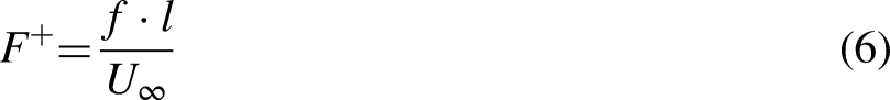
In this study, six dimensionless frequencies (F+=0.5, 1, 2, 4, and 8) are tested, corresponding to pulse repetition rates of 30, 62, 125, 250, and 500 Hz, respectively. Figure 10 reveals how DC60 varies with dimensionless frequency for a fixed actuation voltage of 11 kV.

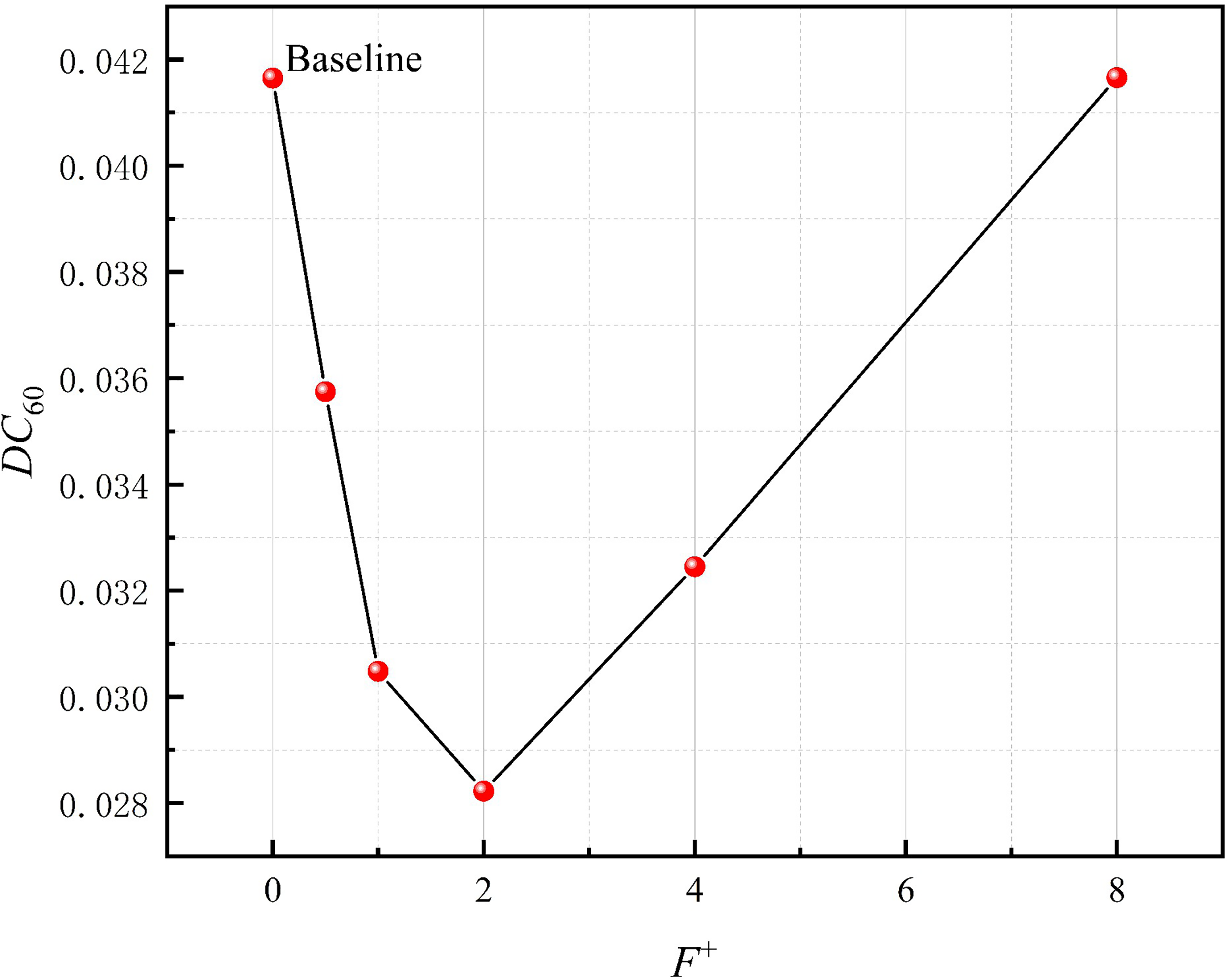
Distortion index at the exit of the bending pipe for different dimensionless frequencies at a fixed voltage of Up-p=11 kV.
According to Figure 10, as the dimensionless frequency increases, the distortion index falls and then rises. This indicates that there is a coupling relationship between the pulsed frequency and the distortion index. The distortion index is minimized when the pulsed frequency is equal to the coupling frequency, which may be related to the shedding frequency of the vortices in the separated shear layer.44,45 In this experiment, when F+=4 (f = 250 Hz), the AIP cross-sectional distortion index is minimized, dropping 14.93% to 0.036279 from the baseline value of 0.042645.
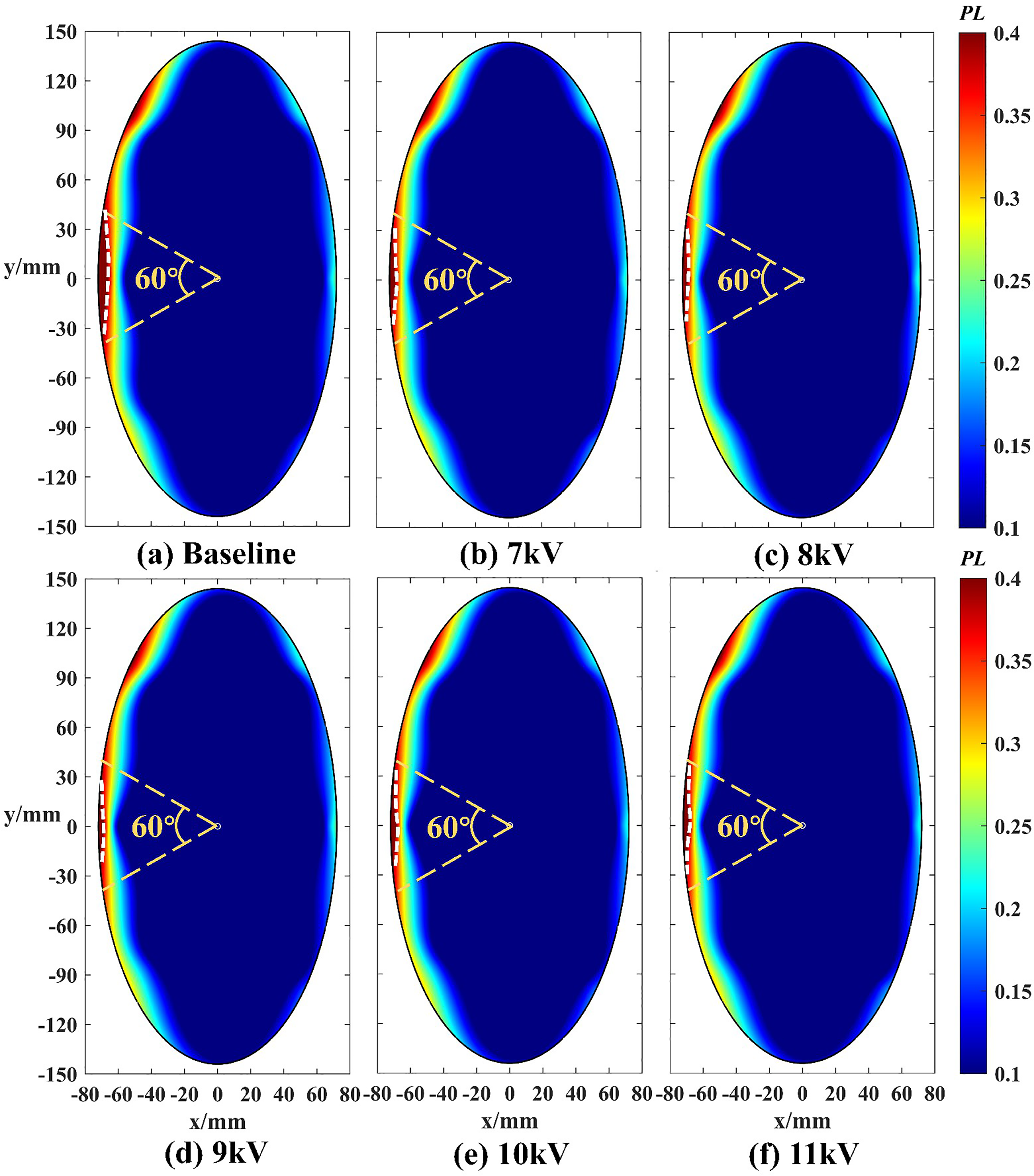
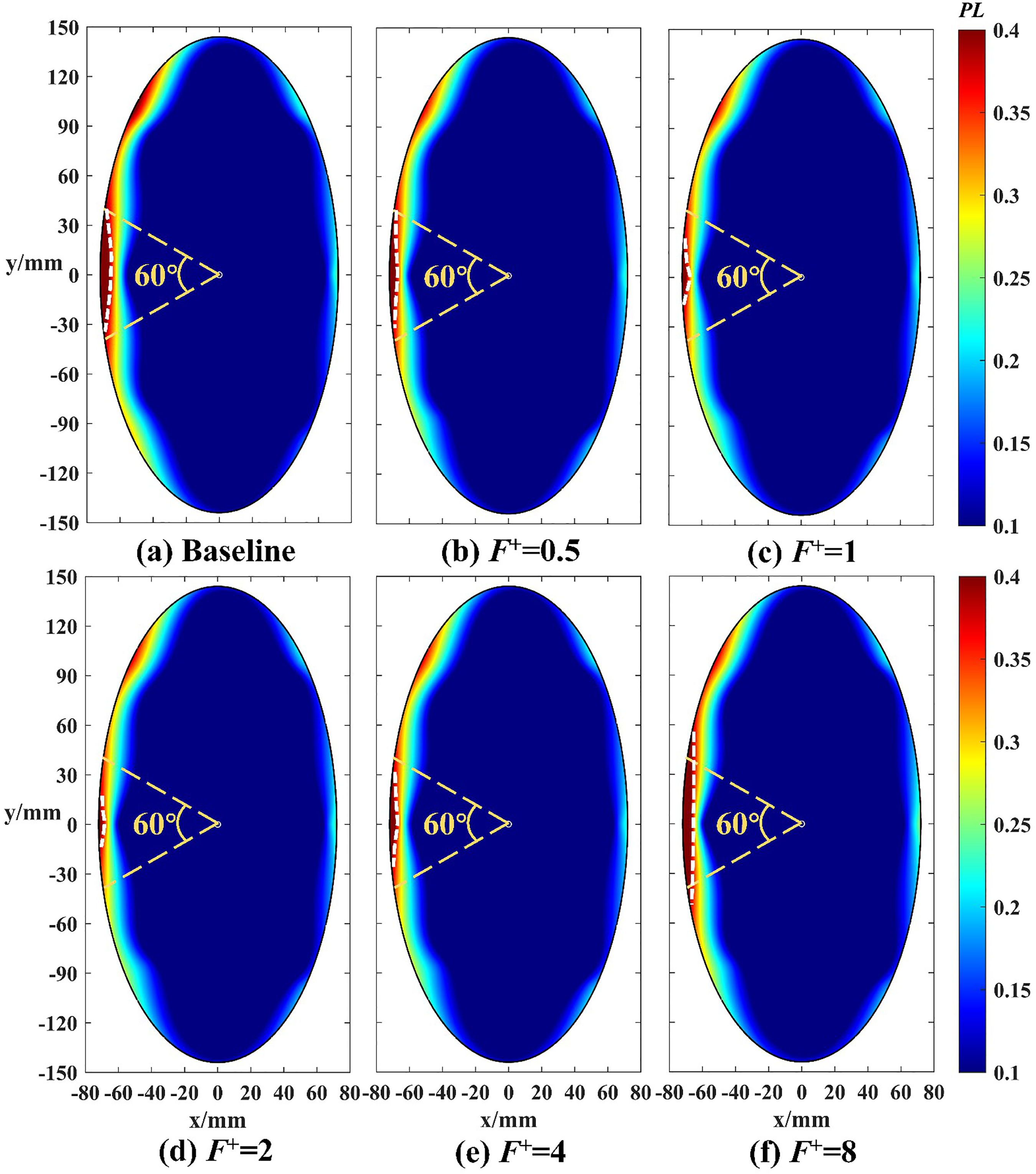
The spatial distribution of PL in the AIP cross-section at different pulsed frequencies is shown in Figure 11. Compared to the baseline, the area of the low-pressure zone is lower in all cases of applied actuation, indicating that the total pressure distortion is reduced at various frequencies. Specifically, as the dimensionless frequency increases from 0.5 to 4, the area of the low-pressure area falls, reaching a minimum at F+=4. Then, as F+ increases from 4 to 8, the area of the low-pressure zone gradually increases. There is little difference in the low-pressure zone area at the two dimensionless frequencies F+=8 and F+=0.5, which is verified by the variation of DC60 in Figure 11. Generally, variations in the low-pressure areas at the different frequencies in Figure 12 follow the same trend as the total pressure recovery coefficient in Figure 11.

Distribution of PL at the AIP cross-section for different dimensionless frequencies at a fixed voltage of Up-p=11 kV. AIP: aerodynamic interface plane.

Distortion index at the exit of the bending pipe for different voltages at a fixed frequency of f = 62 Hz.
AC-SDBD actuator flow control
In this section, an AC-SDBD actuator is applied to the same layout to suppress flow separation within the expansive bending pipe. The AC-SDBD has both steady and non-steady actuation forms. With stable actuation, the supply waveform is a continuous sine wave. Conversely, with varying actuation, the duty cycle of the waveform can be adjusted via a control box to create pulsed frequencies. In this experiment, non-constant actuation is applied and the duty cycle is fixed at 50%. Besides, the applied frequency of the actuator is fixed at 10 kHz and the frequencies mentioned in the following text are the modulation frequency.
Influence of voltage amplitude on flow control effectiveness
A fixed AC-SDBD actuator with a pulsed frequency of 62 Hz is used in this experiment, and actuation voltages of 7 kV, 8 kV, 9 kV, 10 kV, and 11 kV are selected to obtain the relationship between the total pressure distortion index and the voltage amplitude, as figure 12 shows.
Figure 12 reveals that the distortion index gradually falls as the voltage increases from 7 kV to 9 kV, then rises slightly as the voltage rises to 10 kV. After that, it again falls slightly as the voltage climbs to 11 kV. At Up−p = 9 kV, the distortion index reaches a minimum of 0.031804, which is 25.21% lower than the baseline value of 0.042526.
The spatial distribution of PL on the AIP cross-section for different voltage amplitudes is displayed in Figure 13. The area of the low-pressure zone at various voltage amplitudes is smaller than the baseline, indicating that flow separation is suppressed and the distortion index is reduced after actuation is applied.
Distribution of PL at the AIP cross-section for different voltages at a fixed frequency of f = 62 Hz. AIP: aerodynamic interface plane.
As the voltage increases, the area of the low-pressure zone gradually falls. At Up−p = 9 kV, the low-pressure area on the left side of the AIP cross-section almost disappears, indicating that the optimal control effect has almost been achieved. Subsequently, as the voltage continues to rise, the area of the low-pressure zone begins to increase. There is little difference in the area of the low-pressure zone at Up−p = 10 kV and 11 kV, which is reflected in the DC60 value in Figure 12.
Influence of frequency on flow control effectiveness
The relationship between the total voltage distortion index and the dimensionless frequency is obtained, as Figure 14 reveals. The voltage amplitude is 9 kV and F+=0.5, 1, 2, 4 and 8, corresponding to pulsed frequencies of 30, 62, 125, 250 and 500 Hz.
Area-averaged total pressure recovery coefficient and distortion index at the exit of the bending pipe for different frequencies at a fixed voltage of Up-p=9 kV.
According to Figure 14, as the dimensionless frequency increases, the distortion index first drops and then rises. Thus, there may be a coupling frequency at which the flow separation can be optimally suppressed. At dimensionless frequencies of 1 and 4, the distortion index decreases from the baseline figure of 0.041649 to 0.030481 and 0.032450, respectively. These equate to reductions of 26.81% and 22.09%, with similar control effects. When F+=2, the distortion index reaches a minimum of 0.028229, a reduction of 32.22% compared to the baseline. This indicates that the coupling frequency is around 125 Hz in this experiment. When F+ increases to 8, the control effect is at its weakest. Here, DC60 = 0.041659, which is essentially the same as the baseline.
Figure 15 shows the spatial distribution of PL on the AIP cross-section at different voltage amplitudes. As the dimensionless frequency F+ increases from 0.5 to 8, the area of the left low-pressure zone first falls and then climbs. When F+=2, the low-pressure area reaches the minimum and is almost eliminated, indicating the optimal suppression of flow separation. Besides, the corresponding distortion index is at its lowest point at F+=2. When F+=8, the low-pressure area extends to both sides, but the middle section shrinks inward, so the area is almost the same as at the baseline. This may explain why the two DC60 values are almost identical in Figure 14.
Distribution of PL at the AIP cross-section for different frequencies at a fixed voltage of Up-p=9 kV. AIP: aerodynamic interface plane.
Analysis and discussion
In this study, both nanosecond pulsed SDBD plasma actuation and AC-SDBD plasma actuation are applied to suppress flow separation in an expansive bending pipe. Since the inner flow display experiment is not conducted, there is no detailed description of the microstructure and underlying mechanism of the two actuation methods. Nevertheless, based on the combination of previous analyses regarding flow control using DBD plasma actuation and our experimental results, a brief analysis of the control mechanism can be made.
Firstly, for nanosecond pulsed SDBD, the fundamental mechanism is the shock effect,16,17 which involves the quick release of discharge energy on a nanosecond time scale, resulting in rapid heating of the surrounding gas. When the time scale of the heating process is similar to the acoustic scale (∼300 ns), shock waves are generated and subsequently decay rapidly.46–48 The shock wave enhances momentum and energy mixing within the boundary layer and between the boundary and the main flow through strong instantaneous pressure perturbations on the pipe wall. This encourages the boundary layer to resist the adverse pressure gradient and suppress flow separation. Additionally, through the rapid heating effect, nanosecond pulses of SDBD cause a change in the baroclinic term of the vortex transport equation, resulting in a vortex volume change in the flow field.49,50 This actuation-induced vortex develops and moves in the separation flow field, leading the large-scale separation vortex to break up and suppress flow separation. 17 As discussed above, nanosecond pulsed SDBD plasma actuation has both shock wave and induced vortex modes of flow separation suppression. Since the intensity of mixing between the boundary layer and the main flow generated by the shock wave is proportional to the voltage amplitude, DC60 should decrease with increasing voltage amplitude if the shock wave is the dominant mechanism for suppressing flow separation. However, as Figure 8 indicates, there is a peak voltage amplitude that optimizes flow separation suppression. Also, when the optimum voltage amplitude is exceeded, flow separation suppression becomes weaker. This indicates that there is a certain coupling relationship between the actuation effect and the separated flow. Thus, in this experiment, the nanosecond pulsed SDBD suppresses flow separation primarily by generating induced vortices through rapid heating. When the actuation frequency is fixed, the vortex strength of the induced vortex is stronger with the increase of the actuation voltage, but this does not mean that the suppression effect of flow suppression is better. We think that the mechanism of NS DBD to suppress flow separation by generating induced vortices is similar to the VG, which also achieves momentum mixing by generating induced vortices to suppress flow separation. 51 As we know, for a vortex generator, there exists an optimum height to optimize the flow control effect for the same incoming flow, and the height is either too high or too low to achieve optimum results. 52 Analogously to Figure 8, we argue that there also exists an optimal strength of the induced vortex generated by the NS DBD for the fixed Mach number and actuation frequency. When the strength exceeds the optimum value, the induced vortex will worsen the flow field instead of improving it, so that a local minimum of the distortion index occurs at a voltage equal to 8 kV in Figure 8.
Concerning AC-SDBD plasma actuation, the fundamental mechanism is the dynamic effect. This induces near-wall jets through the acceleration of ions under an electric field and promotes momentum transfer between ions and neutral gas molecules. 17 Momentum is directly added to the boundary layer to accelerate the local flow, which suppresses flow separation. As Figure 12 indicates, an increase in voltage amplitude and injected momentum leads to an improvement in the flow separation suppression effect and a reduction in the total pressure distortion index of the AIP cross-section. Figure 12 also reveals that an increase in voltage amplitude and injected momentum leads to a steady improvement in the flow separation suppression effect. Also, the total pressure distortion index of the AIP cross-section gradually decreases. When the voltage amplitude is around 9 kV, the actuation effect is close to the optimum condition under the current parameters. Moreover, the distortion index begins to fluctuate slightly when the voltage amplitude continues to increase, suggesting that increasing the momentum injection no longer effectively suppresses flow separation.
According to Figure 10 and Figure 14, for both of the plasma actuation systems, when the voltage amplitude is fixed and only the pulsed frequency is varied, there is an optimum frequency at which the flow separation is optimally suppressed. An existing investigation 1 established that the type of flow separation in an S-shaped inlet is the “owl face of the first kind,” 53 and there are two foci and saddles in the surface topological structure of this separation pattern. Some scholars believe that the vortex pair that extends downstream originates at the two foci, and they also highlight that the separation flow is extremely volatile, similar to several other unstable shear layers. 54 The expansive bending pipe serves as the geometric basis for the S-shaped inlet and the internal separation flow field is comparable to that of the S-shaped inlet, with similar large-scale vortex shedding. Optimal control is achieved when the actuation frequency is coupled to the vortex shedding frequency within the flow field. Additionally, the optimum coupling frequency differs due to the different dominant mechanisms of the two actuation methods. For nanosecond pulsed SDBD, the optimum dimensionless frequency is at F+=4, while for sinusoidal AC-SDBD, the optimum dimensionless frequency is F+=2.
We also make a discussion about the performance comparison of the two plasma actuators based on Figures 8 and Figure12. First, it can be seen that in the optimal state, the AC-DBD can reduce the distortion index by 25.21%, while the nanosecond pulsed SDBD can only reduce the distortion index by 12.14%, and the latter is only half of the former, which suggests that the AC-DBD has a better flow control effect. Then, comparing Figure 8 and Figure 12, it can also be found that after the actuation voltage exceeds the optimal value, for the nanosecond pulsed SDBD, DC60 increases rapidly. However, for the AC-DBD, continuing to increase the voltage causes the DC60 to vary slightly around the minimum level. Therefore, from the aspect of resisting voltage fluctuation, AC-DBD has better robustness. Finally, it is to be noted that, although the AC-DBD has better flow control performance, this conclusion is specific to the model and wind speed in this experiment. When the experimental conditions change, the conclusions may be adjusted accordingly.
Conclusion
In this experiment, two plasma actuators, the nanosecond pulsed SDBD and the AC-SDBD, are used to suppress flow separation inside an expanding bending pipe under a side wind. Besides, the effectiveness of the SDBD plasma actuators in reducing the total pressure distortion index of the AIP cross-section is verified. Additionally, the effects of voltage amplitude and pulsed frequency on the suppression effect are investigated.
As the voltage amplitude of the nanosecond pulsed SDBD plasma actuator increases, the distortion index first falls and then climbs. This suggests that nanosecond pulsed SDBD suppresses flow separation mainly by generating induced vortices that interact with large-scale vortices. The optimal control effect is achieved only when the induced vortex strength reaches a certain coupling relationship with the large-scale vortex strength of the separated flow. The AC-SDBD suppresses flow separation by generating a near-wall jet that injects momentum into the boundary layer, thereby accelerating the local flow. The suppression effect gradually escalates and reaches an upper limit with increasing voltage amplitude. After reaching the maximum, the control effect remains at approximately the same level as the voltage amplitude increases. Both actuation methods have an ideal pulsed frequency for suppressing flow separation. Optimal control is only achieved when the pulsed frequency is coupled to the frequency of vortex shedding in the flow. The prime frequencies for the two actuation methods differ due to the dissimilar actuation mechanisms in the flow field. With the model and wind speed of this experiment, AC-DBD has a better flow control effect compared to nanosecond pulsed SDBD. On the one hand, AC-DBD can reduce DC60 by 25.21% at the optimal voltage, while nanosecond pulsed SDBD can only reduce DC60 by 12.14% at best. On the other hand, it is that when the actuation voltage is higher than the optimal voltage, nanosecond pulsed SDBD actuation makes DC60 rise rapidly, while with AC-DBD actuation, DC60 will vary slightly around the minimum level, which makes AC-DBD actuation have better robustness.
In this study, the effectiveness of the SDBD plasma actuator in suppressing internal flow separation and reducing the distortion index at the AIP cross-section of expanding bending pipe under side winds is verified. However, the wind speed used in this experiment is low so in future studies, the effectiveness will be confirmed at higher incoming wind speeds. Moreover, in this paper, only a simple analysis of the experimental results is conducted and the specific interaction process remains unclear. The next step is to carry out internal flow field observation experiments that explore the underlying mechanisms of the above findings and further expose the relationship between SDBD plasma actuation and the internal flow field of expanding bending pipes.
Footnotes
Acknowledgments
We would like to acknowledge the support and contributions from the rest of the faculties in the laboratory. This work was supported by the National Science and Technology Major Project (J2019-II-0014-0035) and Foundation Strengthening Fund(JCJQ-2019-077).
Declaration of conflicting interests
The author(s) declared no potential conflicts of interest with respect to the research, authorship, and/or publication of this article.
Funding
The author(s) disclosed receipt of the following financial support for the research, authorship, and/or publication of this article: This work was supported by the Foundation Strengthening Fund, National Science and Technology Major Project, (grant number JCJQ-2019-077, J2019-ⅠI-0014-0035).
Author biographies
Shimin Liu is Student at National Key Lab of Aerospace Power System and Plasma Technology, Air Force Engineering University, People's Republic of China.
Hua Liang is Professor at National Key Lab of Aerospace Power System and Plasma Technology, Air Force Engineering University, People's Republic of China.
Haohua Zong is Associate Professor at School of Mechanical Engineering, Xi'an Jiaotong University, People's Republic of China.
Hesen Yang is Student at National Key Lab of Aerospace Power System and Plasma Technology, Air Force Engineering University, People's Republic of China.
Jie Chen is Student at National Key Lab of Aerospace Power System and Plasma Technology, Air Force Engineering University, People's Republic of China.
Dongsheng Zhang is Student at National Key Lab of Aerospace Power System and Plasma Technology, Air Force Engineering University, People's Republic of China.
Zhi Su is Lecturer at National Key Lab of Aerospace Power System and Plasma Technology, Air Force Engineering University, People's Republic of China.
Weiliang Kong is Lecturer at the Green Aerotechnics Research Institute, Chongqing Jiaotong University, People's Republic of China.