
Abstract
A linear vehicle model is commonly employed in the controller design for an active front steering (AFS). However, this simplified model has a considerable influence on the accuracy of the controller. In this article, an AFS controller using an active disturbance rejection control (ADRC) technique is proposed to prevent this problem. The AFS controller was established in MATLAB/Simulink to control the CarSim vehicle model for verification of the simulation. Under the straight-line driving disturbance condition, proportion-integration-differentiation (PID) control and ARDC substantially decreased with respect to the uncontrolled lateral offset and ADRC performed better than PID control. Under the double lane change (DLC) test working condition, the tracking error of the path, yaw rate, roll angle, and lateral acceleration, and error of the driving direction were used to evaluate the vehicle’s controllability and stability. These evaluation indexes were substantially improved by PID control and ADRC; similarly, ADRC was better than PID control. The tracking error of the ADRC in the presence of parameter variance and external disturbance was significantly smaller than that of PID control. The results have verified that the AFS controller based on ADRC can significantly improve vehicle controllability and stability.
Keywords
Introduction
Currently, driving safety has become the primary consideration in vehicle design and development, and the development of electronic techniques makes active safety control possible. So in recent decades, various active safety control technologies have been applied to vehicles to improve their driving safety, from early anti-lock braking system, direct yaw-moment control (DYC), and electronic stability program to active steering system, collision-avoidance system (CAS), and so on. The application of these systems in vehicles has improved the longitudinal, yaw, and vertical dynamics of vehicles. Longitudinal dynamics control prevents wheel slip; lateral dynamics control prevents a yaw instability; and vertical dynamics control increases the ride comfort. Initially, longitudinal and yaw motions of a vehicle are controlled by changing the longitudinal force on a vehicle, which can improve longitudinal and yaw dynamics. However, the control of longitudinal and lateral motions is effective before the longitudinal force of tire saturation, and DYC controls the vehicle yaw motion by braking the wheel to change the wheel’s longitudinal force to produce yaw moment. However, braking in normal driving will interfere with the driver’s operation and affect ride comfort. 1 Active steering controls vehicle’s longitudinal and lateral motion by changing the lateral force on a vehicle, which prevents these problems and fully utilizes the tire ground adhesion; it is one of the active safety systems that can directly contribute to the stability of a vehicle, especially regarding the controllability and stability. 2 This topic has gained attention in recent years and numerous control strategies for active steering have been proposed.3–8
Active front steering (AFS) is one type of active steering. AFS can be integrated with electric power steering and has been investigated and extensively applied to the yaw stability control of vehicle. Many researchers have deeply studied various yaw stability control methods based on AFS for the vehicle.6–13 Zhao proposed a CAS for autonomous vehicle based on AFS, and designed an AFS robust tracking controller to improve path tracking performance in Wnag et al. 7 Zhao designed a H∞ controller for AFS to ensure that the steering wheel torque accurately and quickly tracks the reference torque, and controllability, stability, and steering portability of a vehicle with AFS can be improved, as presented in Zhao et al. 8 The proportion-integration (PI), 6 proportion-integration-differentiation (PID), and fuzzy-PID control 9 methods were used for controller design of AFS to implement to track ideal yaw rate in the presence of model and parameter uncertainties and external perturbations to enhance yaw stability in emergencies. An AFS robust controller using a normalized left coprime factorization model is proposed in Ji et al. 10 As reported in Song, 11 considering the AFS system of BMW double planetary gear sets as the research object, Song proposed a sliding mode control method for AFS, which realizes the stability control of the vehicle in the tracking reference yaw rate. An AFS design method based on variable structure output feedback control is proposed to improve the stability of vehicles under under-steer and over-steer conditions in Ghoneim. 12 AFS based on quantitative feedback theory and with yaw rate as feedback parameter is discussed in Zhang et al. 13
An additional front wheel angle input provided by AFS that is independent of a driver’s action can improve vehicle’s controllability and stability according to a vehicle’s driving state in various conditions. Due to the additional angle, the steering ratio is variable. By controlling the additional front wheel angle, AFS yields vehicle’s actual steering characteristics that are similar to the ideal steering characteristics.
As previously mentioned, an AFS controller tracks the desired yaw rate to achieve yaw stability control. Following the active disturbance rejection control (ADRC) method is different from the previous method. The ADRC method can offer a linear, simple, and robust solution for some uncertain complex nonlinear systems.14–16 In this article, the control of AFS is realized by the ADRC technique. The exogenous unknown disturbance (road roughness and crosswind) and endogenous unknown disturbance (tire nonlinearity, parameter variation, and load transfer) are considered as the disturbance of a vehicle. The PID algorithm, 17 optimal control algorithm, 18 and H∞ robust control algorithm 19 are used to suppress the disturbance of a system. The PID algorithm has an excellent control effect on a linear system but the actual process is often nonlinear and time-varying. Due to the coupling and uncertainty of the parameters and structure, the application of classic PID method is difficult to get good control effect. The optimal control algorithm and H∞ robust control algorithm depend on a highly precise model. The ADRC proposed by Prof. Han to suppress disturbances does not depend on a controlled system’s accurate model. However, system disturbances are dynamically estimated according to tracking errors to realize the disturbance rejection and target tracking. In this article, disturbance suppression is realized, and the reference yaw rate is tracked by the ADRC technique.
The organization of article is as follows: the “AFS system” section introduces the AFS system, including steering model, tire model, and additional front wheel angle. The “Design of ADRC” section describes the design of AFS controller based on ADRC. In “Simulation experiments” section, some simulation results are provided to verify the effectiveness of different control strategies and to compare their control performance. In the “Conclusion” section, some conclusions are presented.
AFS system
Vehicle steering model
If disregarding the roll and pitch motion, the vehicle lateral motion (yaw rate

Single-track linear vehicle model.
The equations of lateral and yaw motion for the single-track model will be derived as

where
Taking into account the constant longitudinal speed, small slip angles, and front wheel angles, and keeping the tire cornering stiffness linear are the basis of simplified vehicle model for a 2-DOF linear model. The cornering force that acts on the tires is related to the parameters

where
As shown in Figure 1 and mentioned above, a small side-slip angle can be defined as

According to the regulation of the coordinate system in Figure 1,

Then, equation (1) can be rewritten as follows

Considering the derivative of both sides of equation (5) with respect to time t, and substituting
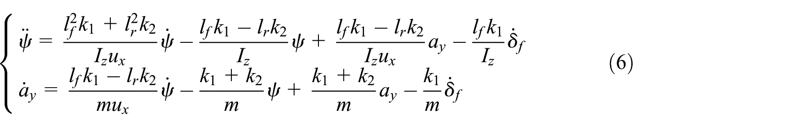
where

Substituting


where


To simplify the linear model and facilitate the design of the controller, the tire cornering stiffness is usually taken as a fixed value, that is, the tire cornering characteristics are linearized. The cornering characteristics of a tire are nonlinear, and especially in the case of a vehicle in extreme working conditions or large lateral acceleration, the nonlinearity of tire cornering characteristics is distinct. The tire cornering stiffness is regarded as a fixed value for the controller design, and the system has parameter uncertainty, which has an impact on the control performance. A robust control design is usually required to eliminate this influence. Eliminating this disturbance in the controller design is easy if the disturbance caused by the parameter uncertainty can be accurately estimated. Since the ADRC technique can estimate and compensate the disturbance resulting from parameter uncertainty, it has strong robustness to the parameter uncertainty, which is investigated in the following section. In this article, the tire side-slip characteristics is linear in the controller design. In the following series of simulation experiments, the lateral tire force data come from built-in tire model of CarSim software, which contains the nonlinear characteristics of the tire. The verification of the controller performance also includes partial verification of the controller’s robustness to parameter uncertainty. The tire in the simulation vehicle is 185/65 R15 and its lateral force characteristics are shown in Figure 2 (data from CarSim software). In Figure 2,

Lateral force characteristics of the tire.
Additional steering angle of front road wheel
AFS is implemented by motion superposition such as BMW’s, its structure is shown in Figure 3. The input end of the 2-DOF planetary gear set is the steering wheel, and its output end is connected to the rack and pinion steering gear.
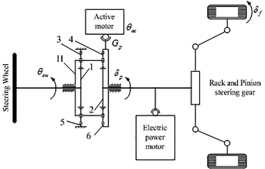
A schematic diagram of active front wheel steering system.
Design of ADRC
Control structure of AFS
By controlling the additional front wheel angle, the AFS controlled by ADRC enables the vehicle to track the ideal yaw rate; the control diagram is shown in Figure 4.

Control structure of AFS.
ADRC employs a feedback controller, whose control inputs are
Let
where
Design of ADRC for AFS
The ADRC technique and the design of ADRC is proposed and discussed by Han. 20 The design process of ADRC for AFS is described as follows:
In the ADRC technique, the exogenous unknown disturbance, endogenous unknown disturbance, and so on are considered as the total disturbance. If the input and output of the system can be measured, the total disturbance can be dynamically estimated using extended state observer (ESO) without knowing the disturbance model, and the suppressing disturbance and tracking target are implemented by the feedback compensation.
Set

where

where
where
The desired reference yaw rate can be tracked by the second-order ADRC as shown in equation (8a). The general structure of the second-order ADRC is shown in Figure 5. The design of ADRC generally includes the following steps.

Control structure of the second-order ADRC.
Transient process
The transient process has an important role in the ADRC according to the research results by Huang.
20
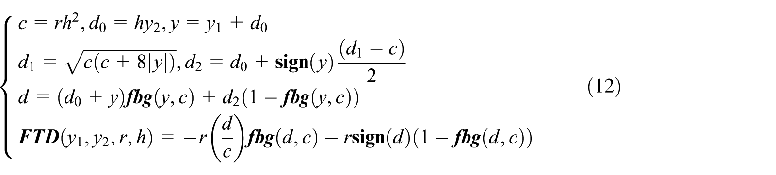
The transient process of the tracking target can solve the contradiction between overshoot and quick-response ability and increase the adjustable scope of the controller parameters, which enhances the controller robustness. The transient process of the tracking target can be realized by the

Equation (13) realizes the transient process of the tracking signal
ESO
If the total disturbance

where
Equation (14) is the third-order ESO after equation (10) for the extended state. Compared with typical nonlinear state observers, the ESO can dynamically estimate the total disturbance of a system in real time. If β1, β2, and β3 and the nonlinear function

where
Feedback control law
An ADRC feedback control law consists of state errors. The state errors of the system—

The error feedback control law of equation (16) includes the yaw rate error and its differential signal. More system state information is employed, which improves the control effect.
Final feedback control law
Setting

Therefore, the

The closed-loop control structure of AFS system.
Stability analysis of ADRC
The system of equations (10) was controlled by ADRC, including the ESO of equation (14) and the control law of equation (17). Wan
22
suggested that the necessary condition for absolute stability of the system is

where
For the convergence of the ADRC controller, ESO, and TD, Zhao has constructed a mathematical proof in his doctoral dissertation. 23
Simulation experiments
To verify the control performance of ADRC in active front wheel steering, MATLAB software was used to control the CarSim vehicle model for the test with straight-line driving and double lane change (DLC) test conditions. The test results in three cases (no control, PID control, and ADRC) are compared. The simulating parameters of ADRC are
The main parameters of the vehicle.

Disturbance rejection test for straight-line driving
Working conditions: The vehicles have no steering wheel input, road surface (roughness coefficient
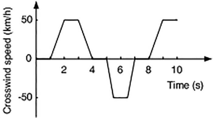
Random crosswind.
Figure 8 shows the results of the disturbance rejection test of straight-line driving. Due to the road roughness disturbance and crosswind disturbance, the vehicle without a controller and the vehicle with a PID controller deviate from the straight path. At the end of the test, the maximum lateral deviation for uncontrolled vehicle is 0.73 m, the maximum lateral deviation for PID-controlled vehicle is 0.49 m, and their driving paths are biased to the left of the vehicle. The maximum lateral deviation for ADRC vehicle during the entire test is 0.14 m, and its driving path is on either side of the desired vehicle path. ADRC has excellent disturbance rejection ability and is superior to PID controller.

Disturbance rejection test for straight-line driving.
DLC test evaluation (ux = 100 km/h)
The speed of the standard DLC test is

The test path and the position of the cone in double lane change test.
Figure 10 shows the results of DLC test for three cases (no control, PID control, and ADRC), where Figure 10(a)–(f) shows the vehicle trajectory, yaw rate, side-slip angle, lateral acceleration, roll angle, and active steering control input (front wheels), respectively.

Double lane change test: (a) vehicle trajectory, (b) yaw rate, (c) side-slip angle, (d) lateral acceleration, (e) roll angle, and (f) active steering angle.
Figure 10(a) shows the vehicle path tracking of the DLC test. The results using the PID controller and ADRC are significantly better than the results without a controller. The uncontrolled vehicle trajectory has a large deviation from the expected path in the S3, S4, and S5 sections. In the straight-line segment (S5 and S6), the lateral displacement overshoot of the uncontrolled vehicle is 0.40 m, which is significantly larger than that of 0.17 m for the PID-controlled vehicle and that of 0.1 m for the ADRC vehicle. Both PID control and ADRC can effectively suppress the lateral displacement overshoot and obtain better path tracking response characteristics, among which ADRC is slightly better than PID control. Both the PID-controlled vehicle and the ADRC vehicle can well complete the DLC test, while the uncontrolled vehicle cannot complete the DLC test. The collision cone phenomenon occurs in the test process.
Figure 10(b) and (c) is the tracking properties of the ideal yaw rate and side-slip angle for uncontrolled vehicle and controlled vehicle, respectively. The tracking errors of the yaw rate and side-slip angles of the controlled vehicle are substantially smaller than those of the uncontrolled, and the response hysteretic time of the uncontrolled vehicle is greater than that of the controlled. The tracking performance of ADRC for the target value is better than that of PID control.
From Figure 10(d) and (e), we determine that the roll angles and lateral acceleration of the PID-controlled and ADRC vehicles are larger than those of the uncontrolled vehicle. To ensure the steering stability of vehicles, all commercial vehicles in use have understeering characteristics. To track the ideal yaw rate, the steering wheel should turn at a greater angle and generate a greater lateral acceleration. If no roll control exists, the change trend of the roll angle is consistent with the lateral acceleration.
The DLC test results qualitatively show that the AFS vehicle controlled by ADRC has a strong path tracking capability.
In this article, the path tracking error index, driving direction error index, lateral acceleration evaluation index, roll angle evaluation index, and yaw rate tracking error index are quantitatively evaluated for the closed-loop controllability and stability. The evaluation indexes are defined as follows:
The path tracking error index

where
The driving direction error index
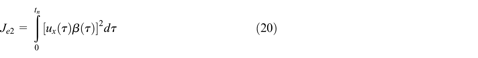
The lateral acceleration evaluation index

The roll angle evaluation index

where
The yaw rate tracking error index

The manipulation stability evaluation indexes of the DLC test are quantitatively calculated according to equations (19)–(23), as shown in Table 2. The descent rate of each evaluation index of the PID-controlled and ADRC vehicles relative to that of the uncontrolled vehicle are provided.
Evaluation index result of double lane change test at ux = 100 km/h.
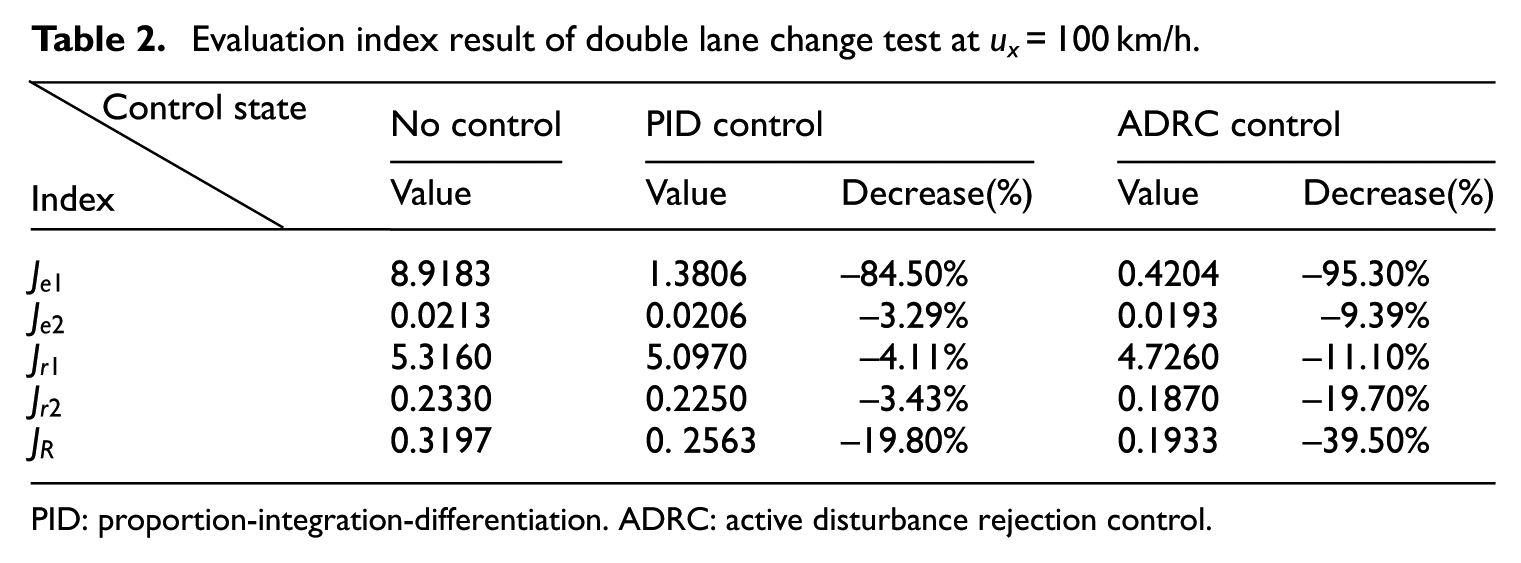
PID: proportion-integration-differentiation. ADRC: active disturbance rejection control.
For the closed-loop control test evaluation indicators
Robust analysis of controllers on sprung mass variation (ux = 100 km/h)
The most important function of the vehicle is to carry passengers or transport goods. The sprung mass of the vehicle will vary in different occasions. For example, the load variation, load distribution variation, and load transfer in turning will cause vertical load variations of the tire and variation in the tire cornering characteristics, which affect the controllability and stability. The following tests were used to verify the robustness of ADRC and PID controller in the presence of the variations in the vehicle sprung mass. In the test, the added mass is assumed to be loaded on the suspension; the increased mass percentages are 0%, 25%, 50%, and 100%; and the other parameters of the vehicle and the controller parameters are not changed. Figure 11 shows the test results. Figure 11(a) and (b) shows the path tracking result and the active input of the front wheel of the vehicle with ADRC, respectively, and Figure 11(c) and (d) is the path tracking result and the active input of the front wheel of the vehicle with PID control, respectively. With the increase of the sprung mass, the active inputs of the front wheel using ADRC and PID control increase, the driving path concentration of the vehicle with ADRC is better than that of PID control, and its deviation from the expected path is smaller than the PID-controlled vehicle. The test results show that ADRC is more robust to variations of the vehicle sprung mass than the PID controller.

Impact of sprung mass variation on controller performance: (a) vehicle trajectory (ADRC), (b) active steering angle (ADRC), (c) vehicle trajectory (PID), and (d) active steering angle (PID).
As previously mentioned, the tires in the CarSim vehicle model have nonlinear characteristics, and its parameters are variable during the working process. In this section, the controller to the robustness of sprung mass uncertainty is verified. Although the other parameters of the test vehicle used by the controller are also fixed values, these parameters, such as suspension parameters, the position of the vehicle mass center, and the moment of inertia, are variable, and modeling errors exist. These results show that ADRC has excellent robustness.
Conclusion
The AFS controller using ADRC technique is proposed to realize the active steering control for a vehicle, follow the ideal yaw rate, and ensure that the vehicle is working within the safety threshold. At the same time, the vehicle with AFS has better controllability and stability. The results show that ADRC controller has better path tracking ability and stronger robustness to the vehicle mass variation than the PID controller. The design procedure of ADRC also indicates that it does not require a high-accuracy model and is not specific to the problem, which has excellent portability. Because ADRC can estimate various disturbances in real time and dynamically compensate them during the working process, it has an excellent control effect on the nonlinear system. The proposed AFS control method based on the ADRC technique provides a new method to deal with nonlinear problems, disturbance suppression, and coupling control.
ADRC technology is developed based on the practical application and lacks in-depth theoretical research. Parameters tuning is also based on personal experience. Future research will focus on these two aspects.
Footnotes
Declaration of conflicting interests
The author(s) declared no potential conflicts of interest with respect to the research, authorship, and/or publication of this article.
Funding
The author(s) disclosed receipt of the following financial support for the research, authorship, and/or publication of this article: This work was supported by National Natural Science Foundation of China under Grant No. 51775268 and Natural Science Foundation of the Jiangsu Higher Education Institutions of China under Grant No. 18KJB590001.