
Abstract
The reasonable layout of hoops can effectively avoid the excitation frequency of engine rotors and greatly reduce the vibration level of pipeline systems. In this study, a spatial pipeline supported by multi-hoops was taken as the object, the method of using genetic algorithm to efficiently obtain the optimal layout of hoops to avoid resonance was investigated. The finite element model of the pipeline system was created as the basic model of optimization, spring elements were applied to simulate the mechanical characteristics of hoop and the influence of spring element direction on the vibration characteristics of pipeline system were mainly described. In the optimization of avoiding resonance for spatial pipelines, the optimization goal was to maximize the first-order natural frequency, the positions of the hoops were converted into the node number as design variables, and the final optimization model of pipeline to avoid resonance was determined on the premise of reasonably setting of constraint conditions for design variables. The genetic algorithm was utilized to solve the optimization model, and two optimization methods were proposed, which were named as “genetic algorithm calling finite element model” and “genetic algorithm updating stiffness matrix” respectively. Finally, a case study was carried out to display the proposed methods. The maximum deviation between the calculation and the test results is less than 1.5% for the first three order natural frequencies, which proves the rationality of the created finite element model of spatial pipeline. Furthermore, the optimization practices show that the reasonable hoop layout of the pipeline system can be obtained by the two optimization methods, but the efficiency of the optimization performed by “genetic algorithm updating stiffness matrix” is much higher than that of “genetic algorithm calling finite element model”.
Keywords
Introduction
As the main transportation channel of fuel, oil, air and other working medium and energy, the reliability of aero-engine external pipeline system directly affects the safety of the engine. Most of the pipelines are installed on the surface of the casing and the pipelines actually used in aero-engines are always curved and spatial structure because their installations are usually limited by space constraints. In addition, the engine pipelines are usually connected with the casing through hoops and during the service process, these pipelines will produce vibration due to the excitations of the engine's inner rotor, transmission components, the pressure pulsation of the pump source, etc. Excessive vibration will cause pipeline failure such as hoop loosening and joint crack, which can affect the safety and reliability of the pipeline system and even the whole aero-engine. Therefore, it is necessary to develop relevant methods to reduce pipeline vibration.
At present, there are almost no direct researches on vibration reduction for aero-engine pipeline system. However, some researchers have carried out the vibration reduction of pipeline system in a few industrial fields, such as aircraft, vehicles, nuclear power, petrochemical transportation, etc. The main vibration reduction methods include viscoelastic damping layers, dynamic vibration absorption (also called tuning mass), electromagnetic dampers, etc. For example, Bi and Hao 1 considered the vibration control of pipeline systems used to transport oil, natural gas, etc, and proposed the use of viscoelastic materials attached on the outer surface of the pipeline to mitigate the seismic induced vibrations. Gao et al. 2 presented the vibration reduction method of attaching the constrained damping layer on the aerospace pipeline conveying fluid and analyzed the effect of the viscoelastic, and constraining layer parameters on the vibration characteristics of pipeline system. Song et al. 3 examined the vibration control effectiveness of the pounding tuned mass damper (PTMD) for pipeline structures using to convey crude oil, natural gas, etc. Bi and Hao 4 proposed a Pipe-in-Pipe (PIP) system to control the vibration of subsea pipeline and this structure actually also belongs to a kind of tuned mass damper (TMD) system. Pisarski et al. 5 applied electromagnetic devices of the motional type to suppress the excessive vibration of a pipe conveying air. Omid 6 developed a passive electromagnetic damper to decrease the vibration amplitude for a pipeline conveying fluid. Recently, Gao et al. 7 provided a detailed review on the current vibration control technologies in hydraulic pipeline system, which included above mentioned methods of vibration reduction. Due to the special working environment of aero-engine, the above-mentioned vibration reduction measures are not easy to implement directly in the aero-engine pipelines, but relevant research methods can provide an important reference for the research of this paper.
The hoops in the pipeline system will provide support stiffness and damping, thus the layout of the hoops will have the most direct impact on the vibration behaviors of the pipeline system. It can be seen that the reasonable layout of the hoops will effectively avoid the frequency of the excitation sources, thereby reduce the excessive vibration of the pipeline system. In the process of aero-engine pipeline design and development, it may be the most feasible and economical method to reduce the vibration level of pipeline system. At present, there have been a lot of researches on the optimization of the hoops layout of pipeline system with the goal of reducing pipeline vibration. For example, Tang et al. 8 presented an optimization model to reduce the vibration of hydraulic pipelines system under the random excitations by rationally designing the positions of the hoops. In their study, the pipeline systems have regular spatial shapes and used for the nuclear industry. Herrmann et al. 9 took a simple L-shaped pipe as an example to simulate automotive pipelines and optimized the mounting position of the pipeline system for vibration reduction. Wang et al. 10 performed the optimization to find the optimal constraint locations for an aeronautical hydraulic pipeline system using non-probabilistic sensitivity analysis. Zhang et al. 11 also did a similar study and optimized the positions of the constraint hoops of hydraulic pipeline system. Liu et al. 12 adopted the particle swarm algorithm to optimize the layout of the hoops for effectively avoiding resonance for a straight pipeline system. However, there are no direct examples on the optimization of hoops layout for the pipeline with irregular spatial geometry in aero-engine.
In order to optimize the layout of hoops for aero-engine spatial pipelines with the aim of reducing pipeline vibration, three factors need to be considered in general, which are establishing a dynamic analysis model of pipeline system, determining a reasonable optimization model and developing an optimization algorithm that can rapidly obtain the optimal solution of hoops layout. There have been a large number of researches on the dynamic modeling and vibration prediction of pipeline system, most of which take straight pipeline and plane pipeline with simple geometry as the object, and the main methods include finite element method,13,14 transfer matrix method15,16 and analytical method.17,18 For the aero-engine pipelines with complex spatial profiles, the most feasible modeling method is using engineering finite element software to model it. For example, Zhou et al. 19 created a finite element model using ANSYS software to perform the anti-resonance design for a spatial aeronautical hydraulic pipeline system. Han and Cho 20 established the finite element model of automotive air conditioning pipeline systems using engineering finite element software and investigated the vibration damping characteristics. For the whole modeling process of the related spatial pipeline, the most important thing is that the corresponding relationship between the actual structure and the final finite element model, but that has not been provided in previous researches. The optimization model here refers to a mathematical model that can effectively describe the entire pipeline hoops layout design, including the objective function, design variables and constraints, etc. In the current research, the goals of pipeline layout optimization include obtaining the smallest displacement or stress, avoiding resonance, and improving fatigue resistance. For the optimization aiming at avoiding resonance, it only needs to calculate the natural frequencies of pipeline system in the implementation, so it should be the preferred optimization objective, and this study is also based on this objective. Generally speaking, optimization solution is the process of obtaining the optimal solution of design variables through iterative calculation, and there are a large number of optimization algorithms available in engineering, such as particle swarm algorithm, 21 genetic algorithm, 22 topology optimization algorithm, 23 etc. In this paper, genetic algorithm is used to optimize the layout of hoops in aero-engine spatial pipeline. In the process of implementing the optimization solution, the most critical things are to effectively combine the above optimization algorithm with the current optimization problem, and seek a method that not only guarantees the accuracy but also has higher calculation efficiency.
This article takes the aero-engine spatial pipeline as the object, systematically describes the whole process of spatial pipeline from finite element modeling to support position optimization of hoops, and tries to confirm the modeling method from pipeline CAD model to finite element model, as well as the method of using genetic algorithm to obtain the hoop optimization layout efficiently. The article is organized as follows. In Section “Finite element modeling of spatial pipeline based on ANSYS software”, the method of creating a finite element model of aero-engine spatial pipeline based on ANSYS software was described, especially the influence of the direction of the spring element used to simulate the hoop support on the vibration characteristics of the pipeline system was described. In Section “Optimization model for avoiding resonance of spatial pipeline”, the hoop layout optimization model of spatial pipeline system was described to avoid the frequency of the aero-engine excitation source. In Section “Optimization solution based on genetic algorithm”, two methods were described to obtain the optimal layout of the hoops, which are named as “genetic algorithm calling finite element model” and “genetic algorithm updating stiffness matrix” respectively. In Section “Case study”, a case study was conducted on a typical pipeline with 3-hoop supports. Firstly, the correctness of the created spatial pipeline finite element model was verified, and then the layout of the pipeline hoops was optimized by the two proposed methods.
Finite element modeling of spatial pipeline based on ANSYS software
The aero-engine spatial pipeline has complex geometrical shape lines, and the design is usually done by 3D CAD software under the constraints of certain route guidelines in the pipeline design and development stage. To establish the corresponding relationship between the actual pipeline routed on the outside of the casing and the finite element model, two main aspects need to be considered, namely, the finite element modeling of the pipe body and the simulation method of the hoop.
Finite element modeling of pipe body
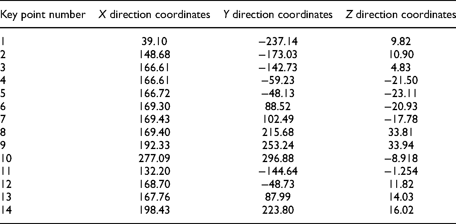
Taking a typical 3-support spatial pipeline as an example, the modeling process of converting the CAD model of the pipe body to the finite element model is described in detail in this section. In Figure 1, the CAD model of the spatial pipeline is shown. If selecting pipe element (PIPE289 is chosen here) to model it, the geometric data of shape line of pipe body must be obtained firstly. Taking into account the flexibility of the subsequent finite element meshing, only the coordinates of several key points of the CAD model need to be extracted, mainly including the coordinates of the two ends of the straight-line segment, the center coordinate of the circle segment, etc. Of course, it also needs to obtain the cross-sectional parameters of the spatial pipeline, that is, the inner diameter and outer diameter of the pipeline. Table 1 lists the required modeling data obtained from the CAD model, and 14 key points coordinate used for modeling are extracted.

CAD model and key points of a spatial pipeline with 3 hoops.
The key point coordinate data of the spatial pipeline extracted from the CAD model (mm).
Based on the data listed in Table 1, the ANSYS modeling module can be used to create the geometric model firstly, and further PIPE289 pipe element is chosen to complete the division of elements. The created finite element model of the pipe body is shown in Figure 2 and the finite element model has a total of 103 elements and 207 nodes.

Finite element model of spatial pipeline created in ANSYS software.
It should be noted that in order to match the subsequent hoop layout optimization, the mesh division of pipe body also needs to satisfy the following requirements. One is that the hoop width, W and the element length, 
Simulation method of hoops
In dynamic modeling, hoops are usually simulated by spring-damping elements.24,25 For the spatial pipeline, the position of the spring element in the pipeline system and the direction of the spring element is issues that must be considered in the hoop modeling process. This section provides the simulating method of hoops with spring elements corresponding to the spatial pipeline.
Simulation of hoops
Since the ultimate goal of this study is the optimization of spatial pipeline to avoid resonance, only the support stiffness of the hoop needs to be considered. In ANSYS software, COMBIN14 spring element can be selected to simulate the mechanical characteristics of the hoop. Figure 3(a) shows the partial diagram of the pipeline hoop. During modeling, two spring elements perpendicular to each other in the x-direction and y-direction can be established to form a spring pair to simulate the support stiffness of the hoop, in which x-direction is the gap of the hoop, and the y-direction is the vertical direction of the metal belt. Of course, a spring pair is usually not sufficient to effectively simulate the support of the hoop, therefore, in actual modeling, multiple spring pairs need to be used. Here, according to previous experience, each hoop position is simulated by two spring pairs (as the Figure 3(b) shows), the dashed frame demarcates the hoop support region and symbols

Partial schematic diagram of pipeline hoop system. (a) Partial diagram of pipeline hoop section. (b) Spring element pairs simulating hoop support.
The influence of the direction of spring element
In the aero-engine, the spatial pipeline is fixed on the casing through hoops, and the hoops fix the pipeline in a direction. In practical applications, the hoops can be fixed on the casing structure by rotating 360 degrees along the pipe axis as required. This raises a question of how to determine the direction of the spring element that simulates the support of hoop. If it is necessary to accurately find the x and y directions described in Figure 3(a), modeling of pipeline will be very difficult. Taking the spatial pipeline as an example with the help of ANSYS software platform, the influence of the direction of the spring element on the dynamic characteristics of the pipeline system is analyzed in the follows.
For the 3-support spatial pipeline system described in Figure 1, two different modeling schemes shown in Figure 4 are chosen and the direction of the spring element is different in each scheme. Firstly, it is assumed that the linear stiffness of each spring element in the x and y directions is both 4 × 10⁶
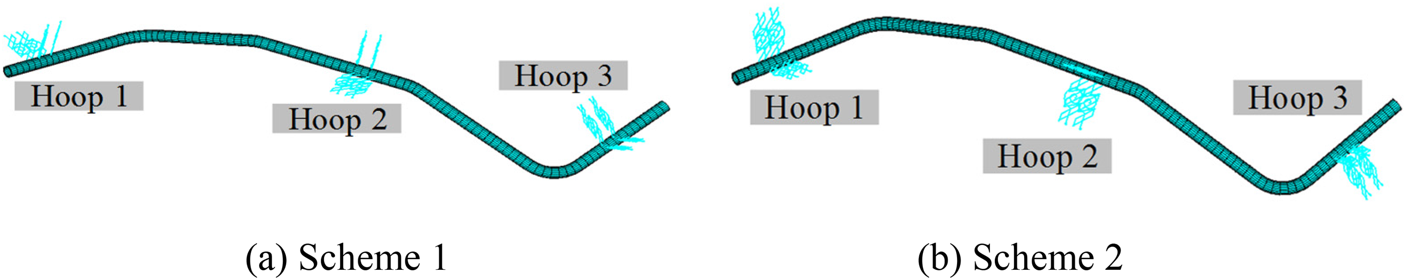
Two different modeling schemes. (a) Scheme 1. (b) Scheme 2.
For scheme 1, the direction of the spring element is consistent with the real fixed direction of each hoop, that is, the direction of the spring element is consistent with the x-axis and y-axis (shown in Figure 3(a)) in the local coordinate system of the straight-line segment of the pipeline. In scheme 2, the direction of each spring element is staggered at a certain angle from the x-axis and y-axis in the local coordinate system. Specifically, the spring element directions corresponding to the first, second, third hoop are staggered by 60°, 45° and 90° respectively. According to the above two modeling schemes, the same natural frequencies can be obtained by modal analysis of pipeline system. This shows that the direction of the spring elements does not affect the analysis results as long as the two spring elements are perpendicular each other in each spring element pair.
In order to further clarify the influence of the direction of the spring element, the stiffness values of the spring element in the above-mentioned spatial pipeline model are changed, and the specific settings are: the linear stiffness of the spring in the x-direction is 5 × 10⁶
It should be noted that the different spring stiffness values are given here only to further evaluate the influence of the spring element direction on the natural frequency of the pipeline system. All specified spring element stiffness values in this section are assumed and do not correspond to actual multi-support pipeline structure.
In summary, it can be concluded that during the finite element modeling process of a spatial pipeline system containing hoops, it is not necessary to pay more attention to the constraint direction of the hoops on the actual pipeline, but only need to accurately determine the position of the hoops and ensure that the two spring elements simulating the mechanical characteristics of the hoops in each spring pair are perpendicular to each other and intersect the pipeline axis. This conclusion brings great convenience to the finite element modeling of the spatial pipeline and the subsequent optimization of the hoop layout.
Optimization model for avoiding resonance of spatial pipeline
In the design criteria of aero-engine pipeline, there are clear requirements for the dynamic characteristics of the pipeline system, that is, the natural frequencies of the designed pipeline system should avoid the excitation frequency of the aero-engine rotor systems. Considering that the overall stiffness of the aero-engine pipeline system is relatively large, and the maximum excitation frequency
Of course, for the actual pipeline, there must be a situation where the first-order natural frequency
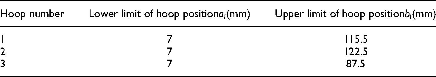
The maximum first-order natural frequency of the pipeline system can be found by adjusting the position of the hoop, so the position of the hoop is the design variable for this optimization problem. According to the pipeline system design guidelines, the hoop cannot support the pipeline at any position of the spatial pipeline. Thus, the variable range of each hoop in the spatial pipeline needs to be described during the optimization process (i.e. the constraint conditions of design variables). Taking the spatial pipeline supported by 3 hoops as an example shown in Figure 5, symbols

Simplified schematic diagram of hoops position of spatial pipeline.
Since the entire optimization process is based on the finite element model of the spatial pipeline, it is also necessary to establish the corresponding relationship between the hoop position and the node number, that is, the original design variables expressed in the hoop position needs to be changed as the node number where the hoop is located. Suppose the reference points (
If the number of hoops in the pipeline system is c, through the above analysis, the final mathematical expression of the optimization model for avoiding resonance of spatial pipeline is as follows:
Optimization solution based on genetic algorithm
Genetic algorithm is a random search algorithm based on natural selection and group genetic mechanism, which has high optimization accuracy and calculation efficiency. Therefore, the optimization model described in Section “Optimization model for avoiding resonance of spatial pipeline” is solved by genetic algorithm in this study. The main variables that also need to be defined for the program include: the dimensionality of the variable (r) which is the number of hoops; the population size (Q) which is the number of initial hoop layout schemes; the number of termination generations of the genetic algorithm (
In particular, two methods of optimization calculation are described here. One is referring to the literatures,26,27 which use the existing genetic algorithm optimization program code developed by Matlab to call the analysis program programmed using APDL language for calculating the vibration characteristics of the pipeline system in ANSYS software to realize iterative optimization calculation. The other is based on the finite element model of free-state spatial pipeline to obtain the total stiffness and mass matrices of the pipeline system, and through self-programming, the position of the hoop is introduced into the stiffness matrix to simulate the dynamic characteristics of the pipeline system which contains the hoop restraint, and then the iterative optimization is realized. Therefore, the two methods are named as “genetic algorithm calling finite element model” and “genetic algorithm updating stiffness matrix” respectively.
Genetic algorithm calling finite element model
Figure 6 describes the procedure of using the optimization program compiled by Matlab to call the modal calculation module of ANSYS to implement the optimization of the hoop layout based on the genetic algorithm. Some specific steps are described as following.

Optimization procedure of hoop position based on genetic algorithm.
In the above optimization process, it is necessary to call ANSYS software through the Matlab optimization program to obtain the natural frequencies of the pipeline system with different hoop positions. This optimization method may be inefficient because it requires to call the ANSYS software repeatedly.
Genetic algorithm updating stiffness matrix
Here, the relevant steps of “Using Matlab program to call ANSYS to perform modal calculation” described in Section “Genetic algorithm calling finite element model” is replaced with “Using the self-developed program to perform modal calculation”. Through this treatment, the optimization program can run in the same software environment, which eliminates the need to call ANSYS software frequently, thereby this optimization can significantly improve the efficiency of the hoop layout optimization calculation of pipeline system.
In ANSYS, the stiffness matrix
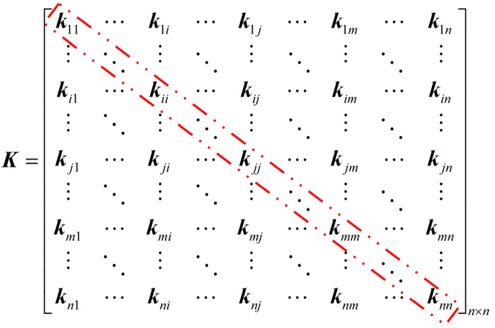
(4)
The pipeline system in the constraint-state is implemented by applying the spring element constraint in the corresponding position of the pipeline hoops in the free-state. The constraint condition is introduced by updating the sub-block matrix in the diagonal position which is specifically highlighted in Eq. (4). If hoop constraints are introduced at node j, the sub-block matrix corresponding to node j needs to be updated as

In the optimization solution of hoop layout for the pipeline system, the genetic algorithm will produce many different hoop layout schemes. The self-developed program updates the total stiffness matrix of the pipeline based on the node number where the hoop is located according to the method described above, and then performs modal calculations. Therefore, the second method is named as “Genetic algorithm updating stiffness matrix”. Its iterative calculation process is roughly the same as described in Figure 6, except that the modal calculation section abandons the calling between the two software platforms, thus significantly improving the calculation efficiency.
However, it should be noted that for more complex pipelines (such as multi-pipeline systems in series or parallel), Method 2 may be difficult to implement. Because it is difficult to extract the required matrix or determine the corresponding nodes of the hoops. Method 1 is a general method, which is also applicable to the above mentioned complex pipelines.
Case study
Description of the problem
The spatial pipeline system supported by 3 hoops described in Section “Finite element modeling of spatial pipeline based on ANSYS software” is taken as an example to demonstrate the effectiveness of the proposed optimization method for the layout of hoops. The geometry and material parameters of the pipeline system are listed in Table 2.
Geometry and material parameters of the pipeline system.

An impact testing system for modal analysis is established to obtain the natural frequencies of spatial pipeline, as shown in Figure 7. The test equipment includes a mobile workstation, an LMS 8-channel portable data acquisition front-end controller, a PCB 086C01 modal force hammer and a PCB 356A01 miniature three-axis acceleration sensor. The Impact Testing module of LMS system is used to conduct modal test experiment on pipeline system, and 5 measuring points are selected. Firstly, the channel and sensitivity of the modal hammer and sensor are set. In order to get more accurate test results, the bandwidth is defined as 1000 Hz and the frequency resolution is 0.25 Hz. Then, tentative hammering is carried out for many times to keep the applied force basically consistent, so as to ensure that the system can determine a suitable measuring range. Finally, the hammering experiment is performed to get the final test results. The frequency response function (FRF) and the coherence function are obtained by hammering the same excitation point twice. When the coherence coefficients corresponding to the natural frequencies of each order are greater than 0.9, the natural frequency value is considered credible, otherwise the measurement is repeated. The tested natural frequencies are listed in Section “Validation of the created finite element model”, which are used to verify the created finite element model.
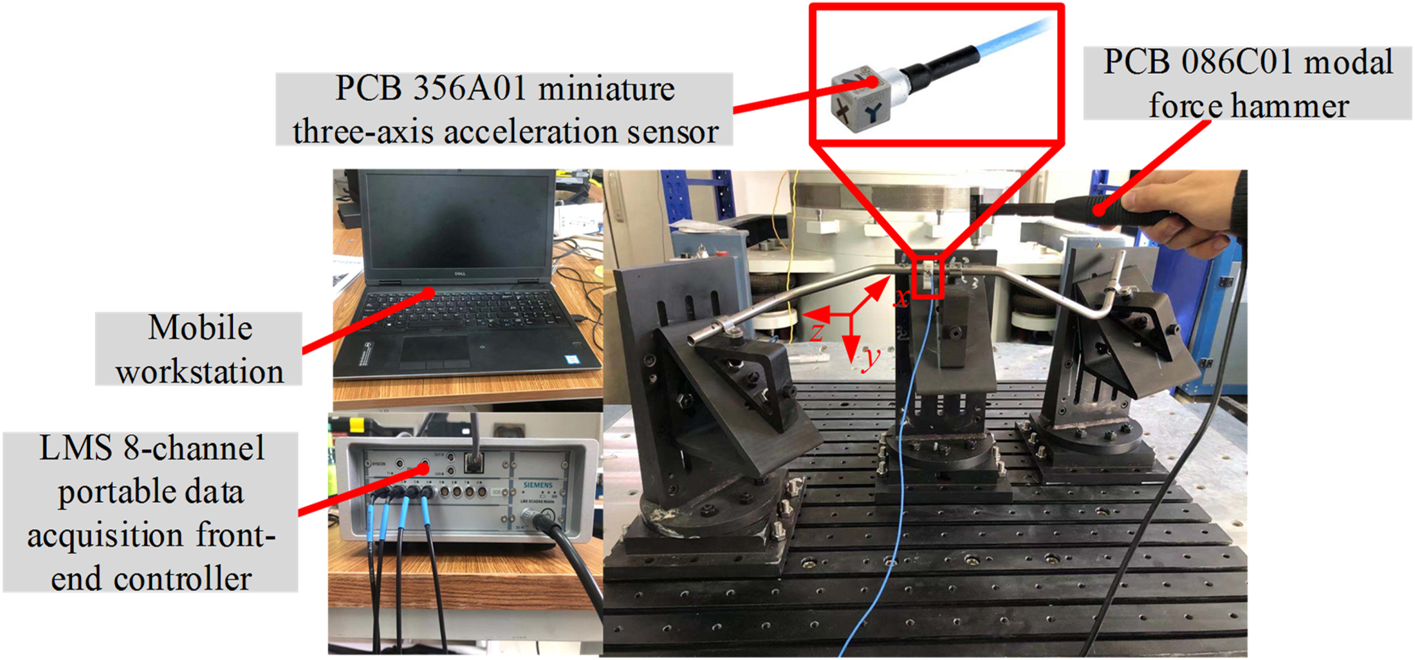
Impact testing system.
Validation of the created finite element model
In the early stage of the experiment, the spring element stiffness value for simulating hoops support under different tightening torques can be obtained by multiple hammering experiments on the constraint pipeline system.
Firstly, according to the impact testing, the first s-order natural frequencies of the spatial pipeline can be measured. Then, the first s-order natural frequencies are calculated according to the simulation model. Finally, the matching calculation of the two natural frequencies is carried out based on genetic algorithm to minimize the deviation of the two frequencies.
The objective function of matching calculation based on genetic algorithm can be expressed as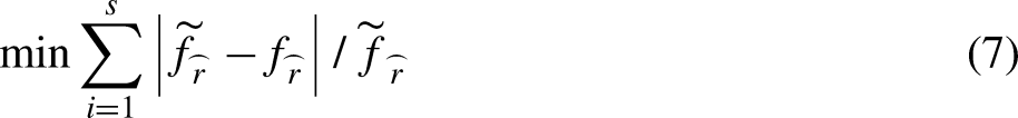
The specific spring stiffness values are
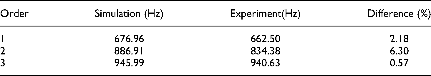
Comparison of natural frequencies of spatial pipelines obtained by analysis and experiments.

From the above table, it can be seen that the maximum difference between the simulation calculation results and the experimental results is 1.07%, which can explain the rationality of this finite element model and can be used as a basic model for subsequent optimization of the hoop support position.
Optimization of hoop support position
Here the excitation frequency of the aero-engine rotor is assumed as
Constraints on the movement range of each hoop.
The two optimization iteration processes are shown in Figure 8. The specific optimization results and the comparison of the calculation efficiency of the two methods are listed in Table 5.

Evolutionary iteration curve of genetic algorithm.
Comparison of the optimization results and computational efficiency of the two methods.

From the comparison in Table 5, it can be seen that the hoop positions and the first-order natural frequency values obtained based on the two optimization methods are the same, which is mainly because the two methods use the same pipeline stiffness and mass matrices. In addition, the optimization results have met the requirements of the constraint condition
Table 5 only lists the node numbers of finite element model, and in order to guide engineering design, the above node numbers need to be changed to the distance from the reference point. According to Eq. (2), the distance between each hoop and the reference point after optimization can be obtained, which are 

Comparison of frequency response function (FRF) before and after optimization.
Comparison of results before and after optimization.

The modal superposition method is used to solve Eq. (8), and the displacement FRF of the system can be obtained as
The acceleration FRF can be obtained by transforming the displacement FRF of Eq. (9).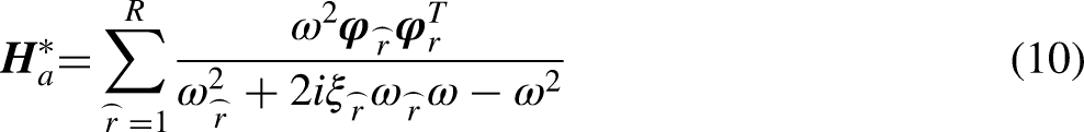
In order to further verify the correctness of the optimization method proposed in this paper, the impact testing is carried out on the pipeline system after optimization to obtain the first three order natural frequency values of the pipeline system. The experimental values and simulation values are compared in Table 7. And the comparison of the FRF of the pipeline system before and after optimization is shown in Figure 10. It can be seen that the first-order natural frequency of the optimized pipeline system increase obviously and avoids the excitation frequency.

Comparison of the tested frequency response function (FRF) before and after optimization.
Comparison of natural frequencies of spatial pipelines obtained by simulation and experiments after optimization.
Optimization of hoops layout for another pipeline system
A new pipeline is selected to verify the generality of the optimization method and in this case, only Method 2 is applied to solve the optimization model. Firstly, the finite element model of space pipeline is created based on ANSYS software, as shown in Figure 11 and the total stiffness and mass matrices of free-state pipeline are extracted. Then the extracted stiffness matrix and mass matrix are introduced into the Matlab program to calculate the natural frequency. Finally, the whole stiffness matrix of pipeline system is updated by adjusting the hoop position based on genetic algorithm and the entire iteration process is shown in Figure 12.

Finite element model of space pipeline.
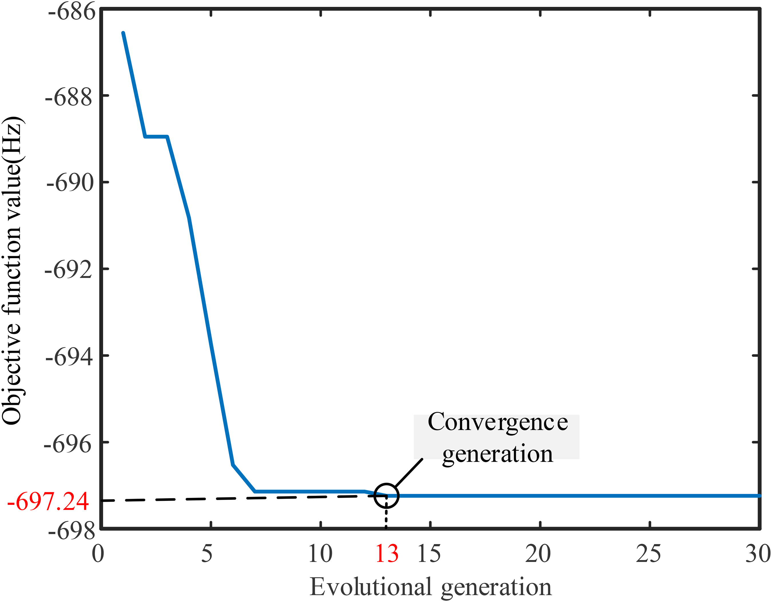
Evolution curve of genetic algorithm.
The first-order natural frequency of the initial pipeline system is 535.13Hz<1.25
Comparison of pipeline system results before and after optimization.
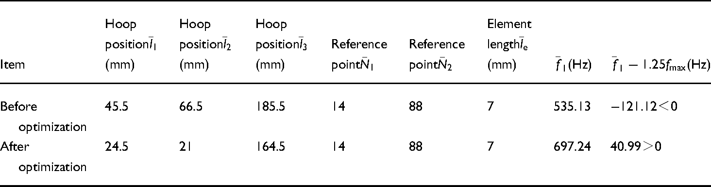
According to the results, it can be seen that the first-order natural frequency of the pipeline system is significantly increased after optimization and the excitation frequency is avoided, which further verifies the rationality of the proposed optimization method.
Conclusions
In this article, a spatial pipeline of aero-engine with multiple hoops was chosen to study the finite element modeling and the method of determining the optimal hoop layout with the objective of avoiding the excitation frequency of the aero-engine rotor system. The relevant conclusions of this study are listed as follows.
The modeling process from the pipeline CAD model to the finite element model and the introduction of the spring element to simulate hoop supports are described. The created finite element model of the spatial pipeline is used to calculate the natural frequencies, and the difference between the calculation result and the experimental result for the first three order natural frequencies is less than 1.5%, which proves the rationality of the finite element model. An optimization model that facilitates the implementation of avoiding resonance study of spatial pipelines is created and the specific description is as follows. Considering that most pipeline systems have large stiffness, resonance can be effectively avoided as long as the first-order natural frequency is large enough, so the optimization objective is to maximize the natural frequency of the first-order of pipeline system. In the optimization based on the finite element model, the hoop position cannot be directly used as the design variable, so this paper proposes a calculation formula for the hoop position and node number, and finally converts the design variable from the hoop position to the node number. Finally, the optimization model for avoiding resonance of pipeline is determined on the premise of setting reasonable constraint conditions. Genetic algorithm is chosen to solve the created optimization model, and two optimization methods are proposed in this study, namely “Genetic algorithm calling finite element model” and “Genetic algorithm updating stiffness matrix” respectively. Both methods can find the optimal hoop layout that maximizes the first-order natural frequency of pipeline system and satisfy the relevant constraint condition. However, method 1 “Genetic algorithm calls finite element model” involves frequent calling between the two kinds of software platforms, thus it is inefficient. Method 2 “Genetic algorithm updating stiffness matrix” can be directly optimized in one software platform, which is more efficient. Specifically, to finish the optimization calculation, method 1 uses 3065.3 s, while method 2 only uses 18.3 s with the premise of the same computing resources.
Footnotes
Acknowledgements
This work was supported by the Major Projects of Aero-Engines and Gas Turbines (J2019-I-0008-0008) and the Fundamental Research Funds for the Central Universities of China under Grant N180312012.
Declaration of conflicting interests
The author(s) declared no potential conflicts of interest with respect to the research, authorship, and/or publication of this article.
Funding
The author(s) disclosed receipt of the following financial support for the research, authorship, and/or publication of this article: This work was supported by the Major Projects of Aero-Engines and Gas Turbines (J2019-I-0008-0008) and the Fundamental Research Funds for the Central Universities of China under Grant N180312012.
Supplemental Material
Supplemental material for this article is available online.