
Abstract
Introduction:
Although the fall protection net installed at the end of the truck escape ramp has a protective effect on trucks and drivers, but lacks sufficient theoretical basis and verification method.
Objectives:
The primary objective of this paper was to design a fall protection net that meets the regulations and research its protection performance.
Methods:
The finite-element method was used to design the overall size, material, mesh length, mesh type, shape, and supporting structure of the fall protection net installed at the end of truck escape ramp, then dummy and truck models were used to impact the fall protection net to verify the rationality of the design. After the design completed, the truck model was used to impact the fall protection net twice to research the cumulative protection performance.
Results:
A fall protection net with a width of 6000 mm, a span of 6000 mm, a depth of 5196 mm, a mesh length of 150 mm, a mesh type of diamond mesh, a shape of 60-degree V-shaped, a supporting structure of steel pipe supporting has a better effect on energy absorption and protection. Within the two consecutive impacts, the residual plastic deformation and stress of the fall protection net generated in the first impact severely affect the protection performance in the second impact.
Conclusion:
It is feasible to use the finite-element method to design and research the fall prevention net installed at the end of the truck escape ramp, and the fall protection net can indeed protect the trucks and drivers, and it should be inspected and maintained after impact to ensure the protective performance in subsequent use.
Introduction
As an auxiliary road, the truck escape ramp is used to enable the brake-failure trucks drive away from the main road in the mountainous area and slow down till stop.1,2 When a truck is driving on a continuous downgrade road in mountainous area, the risk of having an accident is significantly higher than on flat road. 3 Frequent brakes will cause the brake failure due to excessively high temperature. In order to avoid traffic accidents, truck escape ramps need to be set up beside mountain roads.4,5
The truck escape ramps can be divided into four types: ascending grade, horizontal grade, descending grade, and sandpile.6,7 The ascending grade truck escape ramp is widely used in China. After the brake-failed truck enters the ascending grade truck escape ramp, the kinetic energy of the truck gradually decreases till stop because of the gravity and friction resistance. 8 The imperfect design and construction norms lead to the differences in each truck escape ramp. Some truck escape ramps lack sufficient length or energy dissipation devices. 9 If the truck escape ramp cannot stop the brake-failure trucks, the trucks may rush out of the truck escape ramp, which causes a great threat to drivers, as shown in Figure 1.

Truck rushes out of the truck escape ramp.
The expressway administration of Yunnan province in China protects the drivers and trucks in danger by installing a fall protection net on the cliff at the end of the truck escape ramp, as shown in Figure 2. The fall protection net can absorb the kinetic energy of the brake-failure truck through its own deformation. Compared with the protection wall at the end of the truck escape ramp, the fall protection net causes less damage to the trucks and drivers, and has a better protective effect. Since the installation of the fall protection net in 2015, dozens of lives have been saved, the fall protection net set up at the end of the truck escape ramp can protect the life and property of drivers, and it is worthy to be researched.

Truck escape ramp fall protection net.
However, the fall protection net lacks theoretical basis and verification methods in engineering application, the sources of design parameters such as overall size, material, mesh length are nowhere to be found, but the research of net energy absorption system and rockfall safety net can be the reference to design and research the fall protection net. Yan et al. 10 and Ma et al. 11 conducted a truck impact in-situ test on net energy absorption system in the truck escape ramp, and built a finite-element model by using HyperMesh for contrast. The in-situ test and impact simulation results showed that the interception of the flexible net increases the deceleration and reduces the stopping distance of brake-failure trucks.
The rockfall safety net is generally composed of interception devices, supporting structures, and other components. The interception devices are composed of steel wire ropes or metal rings.12,13 In the numerical simulation of rockfall safety net, Govoni et al. 14 built a simplified two-dimensional finite-element model, the deformation and force of this model were close to the reality when rockfall safety net was impacted by rock. In the tensile test of the steel wire rope, it was found that according to the stress–strain curves, the material properties of the steel wire rope can be simulated by the bilinear material model, and the steel wire rope with energy dissipating devices can be simulated by the trilinear material model.15,16 However, the tension-deformation curve of steel wire rope net under dynamic load is highly nonlinear. 17 The tensile failure of the wire rope can be defined by the failure strain.
ANSYS APDL is widely used in the establishment of net finite-element models. During the modeling, “k” and “l” commands are used to create keypoints and lines. After geometric model was done, “lmesh” command is used to generate one-dimensional (1D) element base on the lines, the finite-element model of net is achieved after assigning materials and cross-sectional properties.18,19
Indeed, the net energy absorption systems and rockfall safety nets in the above researches did not consider the impact of both human body and truck on the net, the fall protection net of truck escape ramp needs to consider the contact between the vehicle, the human body, and the fall protection net. This is the main difference between this research and the above researches. Therefore, this paper used finite-element analysis to achieve preliminary design and cumulative protection performance research on the fall protection net at the end of truck escape ramp. ANSYS APDL software was used to design the overall size, material, mesh length, mesh type, shape, and supporting structure of fall protection net. HyperMesh and LS-DYNA software were used to simulate the impact of rigid spheres, Hybrid III 50th dummy, and Ford F800 truck models on fall protection net to verify the rationality of the design parameters. After design was completed, with the aid of stress initialization, the fall protection net was impacted again by the truck to research its cumulative protection performance.
Contact cannot be avoided when it comes to impact. There are many forms of contact, including beam–beam, beam–surface, point–surface, surface–surface contact, and so on, which are commonly realized by penalty function method. Slender structures such as ropes are usually represented by beam elements during simulations. 20 The beam elements belong to 1D element which greatly promotes the calculation efficiency and the factor of friction needs to be considered in the complex interactions involving the beam element. 21 The beam–beam contact is only for the contact between the slender structures, when the interactions come into slender structure and other objects, the contact changes to 1D–3D instead of 1D–1D. 22 For example, the interactions of net–gun, pile–solid, and rock–net are more complicated, so the beam–surface and node–surface contacts will be more widely considered.23,24 In the impact simulation of the net, the net should be the slave part and the impact object acts as the master part.
Methodology
Explicit algorithm
Impact simulation is a kind of explicit dynamic analysis. Which is different from linear static analysis, the equation of motion can be defined as:


When using the central difference method, time step


It can be concluded from equation (9) that smaller minimum element length causes the smaller step size and the longer calculating time. Therefore, the element size of each component is required to be balanced during the pre-processing. In order to reduce the calculating time, mass scaling can also be used to increase the time step, but the increased mass should not exceed 5%.
Mesh sensitivity
The size of the element will affect the analysis results, especially in beam–solid interactions, the length of the rope element in the impact will definitely affect the simulations, so the ropes of net need to be divided into different segments and carry out impacts to analyze the influence of rope element length on overall simulation results, which called mesh sensitivity research.
A 1000 mm × 1000 mm steel wire rope net with a distance of 100 mm between each rope was established. The single rope element was divided into 1, 2, 4, 8, 16, and 32 segments. In this case, the lengths of the rope elements are, respectively, 100, 50, 25, 12.5, 6.25, and 3.125 mm, the four vertices of the net were fixed, a rigid sphere with a radius of 150 mm is used to impact the six nets, the maximum concave deformations of nets are shown as Figure 3.

Maximum deformation with different mesh segments.
When the element of rope is divided into one and two segments, because of the large element size, the calculated results can not meet the accuracy requirement. The maximum deformations are 157.1 and 170.9 mm. When the rope element is divided into four segments, the deformation of the net is smoother and there is no vibration after the impact. The maximum concave deformation of the net is 132.4 mm. When the rope unit is divided into 8, 16, and 32 segments, the net deforms smoothly and the maximum deformations are nearly the same.
Denser rope element is divided, the more accurate the simulation result will be. However, the more segments also mean the larger calculating resources. The calculation time will double as the number of segments doubles, when the segments are 8, 16, 32, the results nearly the same. For saving calculating resources, the rope element is divided into eight segments, which means the length of rope element is 12.5 mm.
Simulation
Overall size
The fall protection net installed at the end of the truck escape ramp is mainly to protect the brake-failure truck, so its overall size needs to be designed with reference to Chinese norm GB 1589-2016 which stipulates that the maximum width of trucks, semi-trailers, and trailers is 2550 mm, and the maximum height is 4000 mm. When designing the overall size of fall protection net, the condition that two trucks enter the truck escape ramp simultaneously should be considered, 25 so the width of the fall protection net should be set to 6000 mm.
Take the grade ascending gravel arrester bed truck escape ramp mainly used in China as an example, when the truck rushes into the truck escape ramp, the truck is subject to gravity, air resistance, and rolling friction resistance from aggregates in the arrester bed. The kinetic energy of the brake-failure truck is mainly reduced due to gravity and rolling friction resistance. Therefore, the air resistance can be ignored when analyzing the forces of the brake-failure truck on truck escape ramp. The forces acting on brake failure vehicle are shown in Figure 4.


Material
Safety nets in engineering applications are generally made by wire ropes or nylon ropes. The properties of these two rope materials are quite different, so they need to be simulated by different elements in ANSYS APDL. The wire ropes are simulated by LINK160 elements with density of 7.85 × 10⁻⁹ ton/mm3, Young’s modulus of 2.1 × 10⁵ Mpa, Poisson’s ratio of 0.3, yield strength of 1.57 × 10³ Mpa, tangent modulus of 2.8 × 10⁴ Mpa, a failure strain of 0.05, using the plastic kinematic material model which is in line with the national standard norms. 28 The nylon ropes are simulated by LINK167 elements with density of 1.1 × 10⁻⁹ ton/mm3, using the cable discrete beam material model.
The rigid sphere was used to impact the fall protection nets in two different materials and the energy dissipation capacity of the fall protection net were compared and analyzed according to the deformation of net and the velocity, kinetic energy changes of the rigid sphere. In order to enlarge the difference between the elastoplastic deformation of the wire rope net and the elastic deformation of the nylon rope net, the size of the fall protection net is amplified from 6000 mm × 6000 mm to 72,000 mm × 72,000 mm. Rigid sphere impacted the fall protection net at an initial velocity of 5000 mm/s and a diameter of 20,000 mm, the diameters of the wire rope and nylon rope in fall protection net keep the same. The maximum deformation of the fall protection nets in two different materials during impact are shown in Figures 5 and 6, the velocity and kinetic energy changes of rigid spheres are shown in Figures 7 and 8.
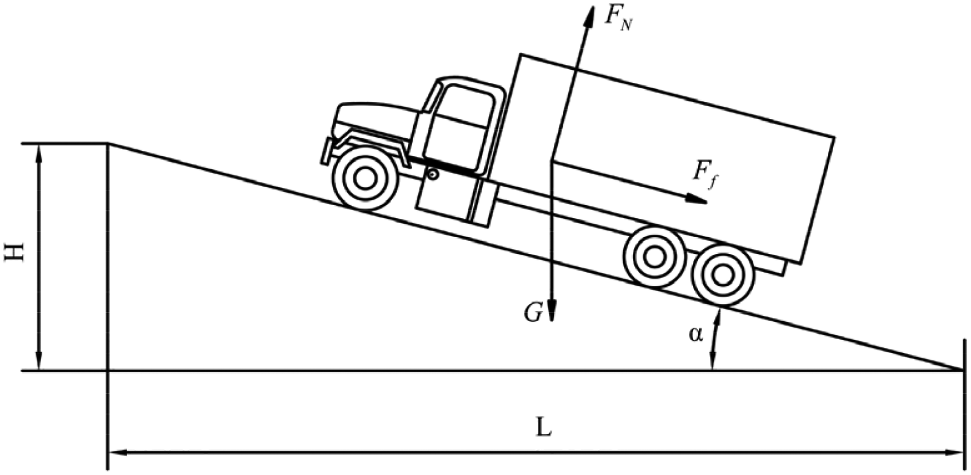
Forces acting on the brake-failure truck in truck escape ramp.

Maximum deformation of wire rope net.

Maximum deformation of nylon rope net.

Velocity of rigid sphere.
When the rigid sphere impacts the wire rope net and the nylon rope net, the wire rope net has elastoplastic deformation, the sphere obtains a bigger deceleration. The wire rope net generates a maximum concave deformation of 7493 mm, and the velocity of rigid sphere finally stabilizes at upward 882 mm/s after rebound. When rigid sphere impacts the nylon rope net, the nylon rope net has an elastic deformation, which causes the velocity of rigid sphere changes more smoothly but a smaller deceleration. The nylon rope net generates a maximum concave deformation of 10,711 mm, and the velocity of rigid sphere finally stabilizes at upward 4500 mm/s after rebound.
During the impact, the initial velocity of the rigid sphere is
Velocity and kinetic energy attenuation rate of rigid sphere.

Mesh length
The fall protection net installed at the end of the truck escape ramp is not only to protect the brake-failure trucks, but also to protect the drivers from falling into the cliff. When protecting trucks, the mesh length can be large or small, when the drivers fall into the fall protection net, if the mesh length is too large, the driver’s limbs may pass through the fall protection net and cause secondary injury. In order to prevent such fall injuries, the mesh length of fall protection net should be designed according to dummy impact.
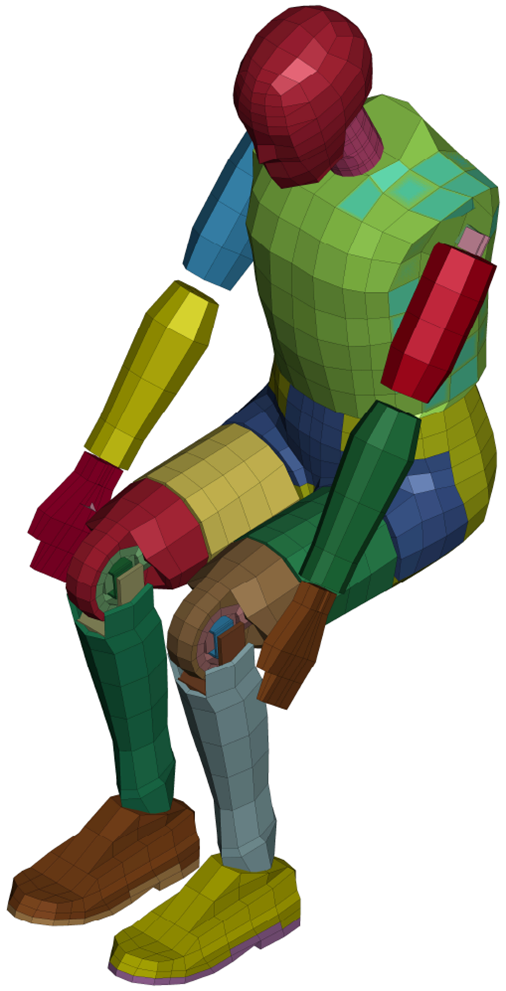
The Hybrid III dummy is extensively used in automobile industries, it can be divided into three categories according to the size: 5th means female dummy with height of 1520 mm and weight of 0.054 ton, 50th means male dummy with height of 1750 mm and weight of 0.078 ton, 95th means male dummy with height of 1880 mm and weight of 0.100 ton. 29 Truck drivers in China are almost male and Asians are generally shorter than Europeans and Americans, so the Hybrid III 50th dummy was chosen to impact the fall protection net to simulate the behavior of drivers falling into the fall protection net for designing the mesh length of fall protection net. Assuming that there are two postures when driver falling into the fall protection net. The first posture is a sitting posture, dummy’s buttocks and legs are first in contact with the net, and the deformation of net and buttock, legs absorbs kinetic energy and generates buffering. The second posture is a squat posture, dummy’s feet are first in contact with the net, and the deformation of the net and leg absorbs kinetic energy and generates buffering. The dummies in sitting and squat postures are shown in Figures 9 and 10.

Kinetic energy of rigid sphere.

Dummy with sitting posture.
The mesh length should be designed according to the size of the dummy's limbs and assuming that arms and legs of the dummy are regarded as truncated cones. After measurement, the dummy's foot length is 327 mm, the palm width is 105 mm, the minimum diameter of the forearm is 69 mm, the maximum diameter of forearm is 97 mm, and the minimum diameter of calf is 97 mm and the maximum diameter of calf is 111 mm. The mesh length of fall protection net is designed as four types: 50, 100, 150, and 200 mm according to the above dimensions, as shown in Figure 11.
Dummy with squat posture.
The impact conditions were set as the dummy impact the 6000 mm × 6000 mm fall protection nets with an initial height of 1500 mm and an initial velocity of 2000 mm/s, the four vertices of the fall protection net were constrained. The dummy was affected by gravity, and the fall protection net was not affected by gravity in the impact. The diameter of the wire rope used in the fall protection net was according to GB 8918-2006 and GB/T 20118-2017 norms and chosen as 8 mm.
When the sitting dummy impacts the fall protection net, the states of the dummy and the fall protection net are shown in Figure 12. The dummy was in contact with the fall protection net, and the fall protection net generated a deformation that conforms to the shape of the human body. The limbs of the dummy did not pass through the fall protection net.

Fall protection net with mesh length of 50, 100, 150, and 200 mm.
When the squat dummy impacts the fall protection net, the states of the dummy and the fall protection net are shown in Figure 13. Because the feet and legs of the dummy contact the fall protection net before the buttock, the contact area with the fall protection net was much smaller than sitting posture impact condition. When the squat dummy impacts the fall protection net with the mesh length of 200 mm, the hands, calves, and feet of the dummy passed through the fall protection net and were exposed outside the net, which caused the fall injury of dummy, so the mesh length of 200 mm is not considered when designing the mesh length of fall protection net.

Sitting dummy impact fall protection nets with mesh length of 50, 100, 150, and 200 mm.
When dummy impacts fall protection nets in two postures, fall protection nets with mesh length of 50, 100, and 150 mm all had a good protective effect on the dummy. Additionally, the influence of self-weight should be also considered when installing and using the fall protection net. The weights of fall protection nets with three kinds of mesh length are shown in Table 2. Among them, the fall protection net with a mesh length of 150 mm has the lightest weight and the minimal initial deformation caused by gravity, so the mesh length of the fall protection net should be set as 150 mm.
Weights of fall protection net with different mesh length.

Mesh type
The mesh type of fall protection net can be divided into square mesh and diamond mesh. The square mesh means that the ropes of each mesh are perpendicular to each other. The diamond mesh means that the lateral ropes and the ropes of each mesh are not perpendicular to each other. The fall protection nets with mesh type of square mesh and diamond mesh are shown in Figures 14 and 15. The difference in mesh type leads to a single fixed point of the square meshed fall protection net connects to horizontal and vertical ropes, while a single fixed point of the diamond meshed fall protection net connects horizontal, vertical, and oblique ropes.

Squat dummy impact fall protection nets with mesh length of 50, 100, 150, and 200 mm.

Square mesh.
Based on the possible accident in Figure 2, the cab of truck was used to impact the fall protection net for designing the mesh type; the cab model was taken apart from the Ford F800 model with a length of 2536 mm, a width of 2360 mm, a height of 2228 mm, and a weight of 2.4 ton. The initial velocity of the cab impact the fall protection net was 5000 mm/s.
Under the impact of cab, the square meshed fall protection net generated partial concave deformation, the diamond meshed fall protection net generated overall concave deformation due to the oblique rope. Besides, the deformation of diamond meshed fall protection net was smaller than square meshed fall protection net. When T = 0.5 s, the concave deformation of square meshed fall protection net is 430 mm, and the concave deformation of diamond meshed fall protection net is 395 mm, as shown in Figures 16 and 17. During the impact, the maximum concave deformation of square meshed fall protection net is 1521 mm, and maximum concave deformation of the diamond meshed fall protection net is 610 mm.

Diamond mesh.

Cab impact square meshed net.
The rope tension changes of square meshed and diamond meshed fall protection net are shown in Figures 18 and 19. The square meshed fall protection net generated partial concave deformation, which leaded to slower tension transmission. The tension of the horizontal and vertical ropes reached the peak at T = 0.9 s, meanwhile the tension of the horizontal rope was 8.78 × 10⁴ N. The tension of the horizontal rope was reduced to 2.87 × 10³ N at the end of impact. When diamond meshed fall protection net was under impact, the oblique rope is quickly tensioned and the tension reached the peak at T = 0.6 s, the tensions of horizontal and vertical ropes reached the peak at T = 0.64 s subsequently, the maximum tension of horizontal rope is 8.51 × 10⁴ N. The rope tension fluctuated due to component interference between the cab and fall protection net from T = 1 s to T = 1.2 s. The tension of the horizontal rope was reduced to 1.48 × 10⁴ N at the end of impact.

Cab impact diamond meshed net.

Rope tension of square meshed net.
According to the above simulations, when the fall protection net was under impact of the cab, the tension of diamond meshed fall protection net transmits faster and limits the displacement of the driver's cab with a smaller concave deformation, so the mesh type of the fall protection net should be designed as diamond mesh.
Shape
The fall protection nets in the above designs have only width and span, which are called as planar fall protection net. When the cab impacts the planar fall protection net, the resultant force of the fall protection net on the cab makes the rebound velocity direction perpendicular to the plane of net, which is not the best energy dissipation way for deceleration. In order to decrease the kinetic energy, this paper introduces a V-shaped fall protection net composed of two planar fall protection nets. Compared with a planar fall protection net, frictions and squeezes between the V-shaped fall protection net and the cab maximize the kinetic energy consumption. The overall size of the V-shaped fall protection net still needs to meet the requirements of a width of 6000 mm and a span of 6000 mm. Therefore, the angle between the two meshes is 60°, and the depth is 5196 mm. The planar and V-shaped fall protection net are shown in Figures 20 and 21.

Rope tension of diamond meshed net.

Planar fall protection net.
According to the impact condition of the cab impact diamond meshed fall protection net, the impact condition of cab impact V-shaped fall protection net was built as the cab impacts the V-shaped fall protection net vertically downward at an initial velocity of 5000 mm/s. Two sample nodes were set on the longeron, and the vertical velocities of the sample nodes were analyzed to judge the deceleration and energy absorption effects of two fall protection nets.
Under the impact of the cab, the maximum concave deformation of the planar fall protection net was 610 mm, as shown in Figure 22. When the V-shaped fall protection net impacted by the cab, the deformation area of the net was smaller due to the constraints of the six fixed points. The maximum concave deformation of V-shaped fall protection net was 580 mm, as shown in Figure 23.

V-shaped fall protection net.

Maximum deformation of planar fall protection net.
When impacting the planar fall protection net, the cab contacted the net at a velocity of 3830 mm/s, and decelerated to 0 within 0.18 s. After the rebound, cab reached a maximum velocity of 2758 mm/s, and finally stabilized at upward 2408 mm/s, as shown in Figure 24. When impacting the V-shaped fall protection net, the cab contacted the net at a velocity of 3880 mm/s, and the velocity decelerated to 0 within 0.28 s. The cab reached a maximum velocity of 2726 mm/s, the two meshes of the net rub and squeeze the cab caused the velocity fluctuation and gradually decreased within T = 1.4 s to T = 1.9 s. The velocity of the cab after the rebound was finally stabilized at upward 1069 mm/s, as shown in Figure 25. According to the above simulations, the V-shaped fall protection net generated smaller deformation than the planar fall protection net during the impact of cab, and consumed more kinetic energy also had a better deceleration and energy dissipation effect. Therefore, the shape of the fall protection net should be designed as V-shape.

Maximum deformation of V-shaped fall protection net.

Velocity of cab when impact planar fall protection net.
Supporting structure
The V-shaped fall protection net is composed of planar fall protection nets; it has only two meshes, which lacks protection in the lateral direction of the trucks. Additionally, the installation of the fall protection net also needs to be considered. Therefore, it is necessary to set the left and right meshes of the net in the lateral direction and add the anchor rope to constrain the fall protection net at the end of truck escape ramp. According to the different support and fixing forms of the fall protection nets, two supporting structures are proposed in this paper. One is wire rope supporting fall protection net with six anchor ropes and six anchors, and the other is steel pipe supporting fall protection net with four anchor ropes and six anchors (the supporting steel pipe fixed by two anchors). The differences in fixing forms will cause the differences in deformation mechanism and the protection performance of the fall protection nets. 30
The wire rope supporting fall protection net is composed of meshes, anchor ropes and fixed by four upper anchor ropes and two bottom anchor ropes at six anchors. The supporting wire ropes connect the anchor rope and the meshes, and support the meshes. The inside meshes are close to the truck escape ramp, and the outside meshes are far away from the truck escape ramp. Because the anchor ropes and support ropes need to withstand greater tension, the diameter of the anchor ropes and support ropes is increased to 10 mm. The diameter of the wire rope in the meshes keeps 8 mm. The wire rope supporting fall protection net is shown in Figure 26.

Velocity of cab when impact V-shaped fall protection net.
The steel pipe supporting fall protection net is composed of meshes, anchor ropes, and supporting steel pipes. The difference between the wire rope supporting fall protection net and steel pipe supporting fall protection net is that the supporting steel pipes is used instead of the supporting wire ropes. The steel pipe supporting fall protection net is fixed by two upper anchor ropes and two bottom anchor ropes. The diameter of the anchor ropes is 20 mm, the outer diameter of the supporting steel pipe is 100 mm, and the inner diameter is 80 mm. The supporting steel pipe is Q235 type and simulated by BEAM161 elements with a density of 7.85 × 10⁻⁹ ton/mm3, Young's modulus of 2.05 × 10⁵ MPa, yield strength of 235 MPa, and Poisson's ratio of 0.3. It also adopts plastic kinematic material which can represent the mechanical property of actual steel pipe. The steel pipe supporting fall protection net is shown in Figure 27.
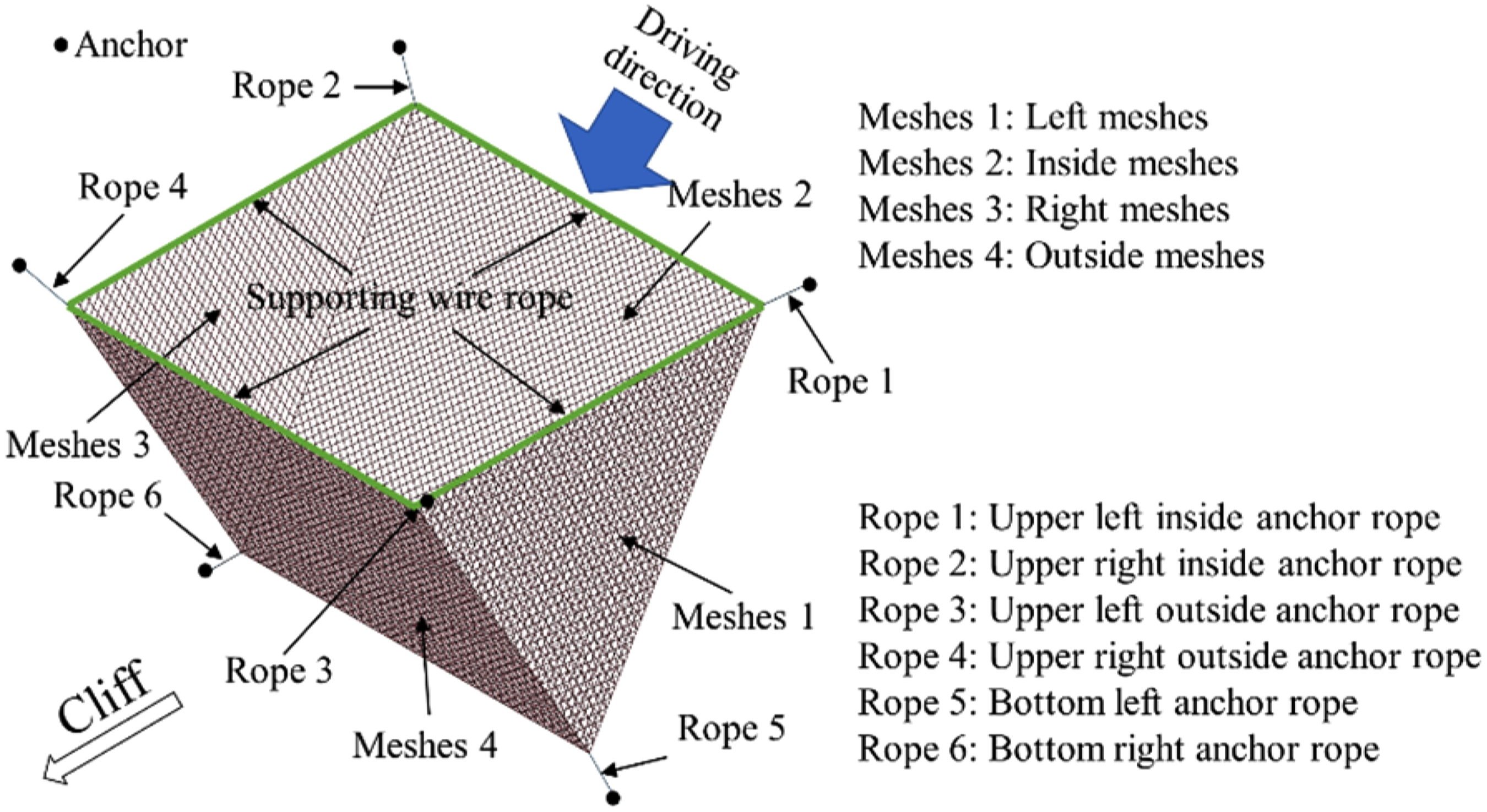
Wire rope supporting fall protection net.
The cab and the truck were used to impact the fall protection net. The two different nets were comprehensively analyzed according to the anchor rope tension, the integrity of the net, and the velocity changes of the cab and truck.
Cab impact conditions
There is a horizontal offset distance of 1000 mm between the cab model and the center of the fall protection net, and the cab impacted the fall protection net vertically downward at a velocity of 5000 mm/s. The total impact simulation time was 3 s.
When the cab impacted the wire rope supporting fall protection net, there were three contacts between the cab and inside meshes, outside meshes. Firstly, the cab contacted the inside meshes. Secondly, the cab contacted the outside meshes. Thirdly, the cab contacted the inside meshes again, which correspond to the three peaks of the anchor rope tension, as shown in Figure 28.
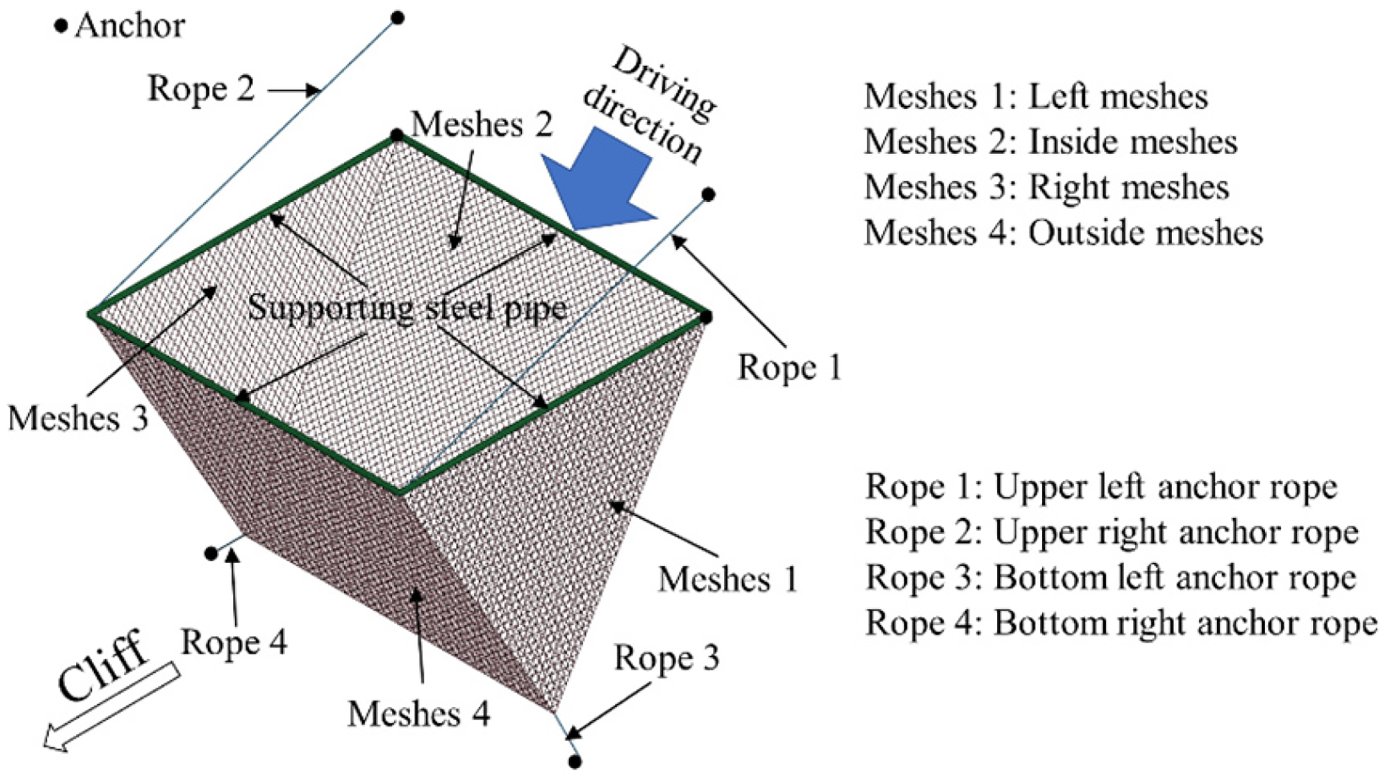
Steel pipe supporting fall protection net.
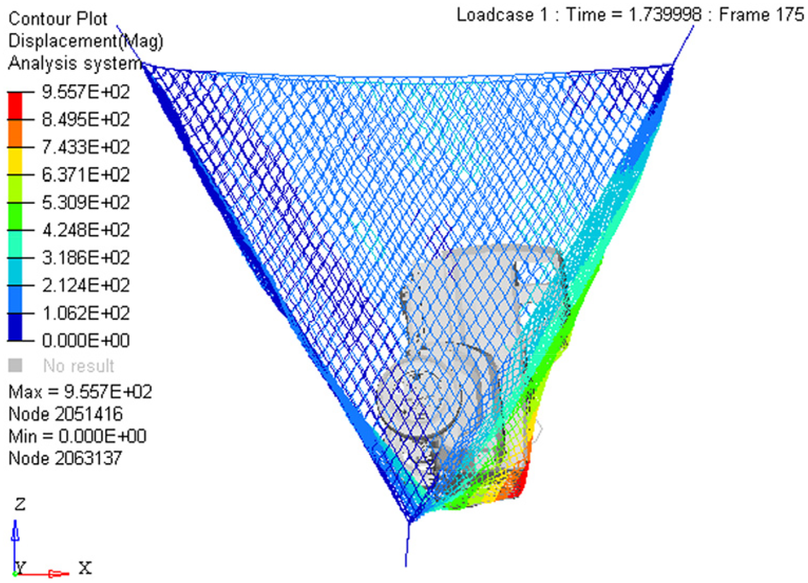
The cab first contacted the inside meshes during downward movement, and the concave deformation of the inside meshes caused the downward movement of the fall protection net. The six anchor ropes generated the first peak of tension at T = 1.17 s, the bottom left anchor rope had the biggest tension of 1.27 × 10⁵ N. During the first contact, the inside meshes pushed the cab to the outside meshes in the process of recovering elastic deformation. The cab impacted the outer mesh and caused the six anchor ropes to generate the second peak of tension at T = 1.74 s, the bottom left anchor rope has the biggest tension of 1.46 × 10⁵ N. Meanwhile, the outside meshes of fall protection net generated the biggest concave deformation of 956 mm, as shown in Figure 29. When the outside meshes recovering elastic deformation, the cab was pushed by the outside meshes and contacts the inside meshes again, generates the third peak of tension at T = 2.53 s, the bottom left anchor rope still has the biggest tension of 1.22 × 10⁵ N. During the impact, the tension of bottom left anchor rope was greater than other anchor ropes, and the supporting wire ropes showed obvious tensile deformation under the impact.
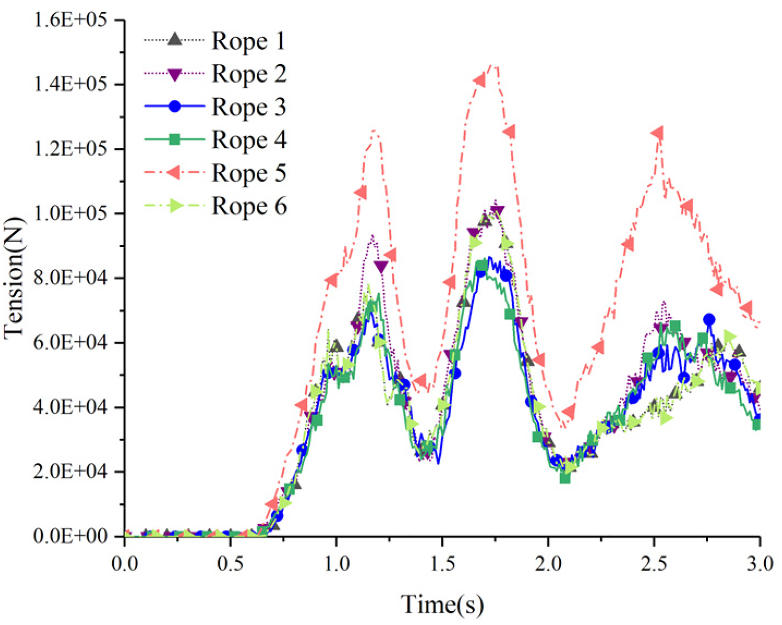
Anchor rope tensions of wire rope supporting net.
When the cab impacted the steel pipe supporting fall protection net, the anchor rope tension also showed as three peaks, as shown in Figure 30. When the cab impacted the inside meshes for the first contact, the first peak of anchor rope tension generated at T = 1.17 s, the upper left anchor rope generates the biggest tension of 1.30 × 10⁵ N. The cab was pushed to the outside meshes by the inside meshes while continuing move downward. The cab then contacted the outside meshes and caused the anchor rope to generate the second peak of tension at T = 1.71 s. The tension of upper left anchor rope was still the biggest, which was 1.77 × 10⁵ N and correspond to the maximum convex deformation of fall protection net of 952 mm, as shown in Figure 31. The cab was pushed by the outside meshes and contacted the inside meshes again and generated the third peak of tension at T = 2.56 s, meanwhile the bottom left anchor rope generated the biggest tension of 1.60 × 10⁵ N. During the impact, the tensions of anchor ropes are relatively the same, and the supporting pipes showed no obvious bending deformation.
Maximum deformation of wire rope supporting net.
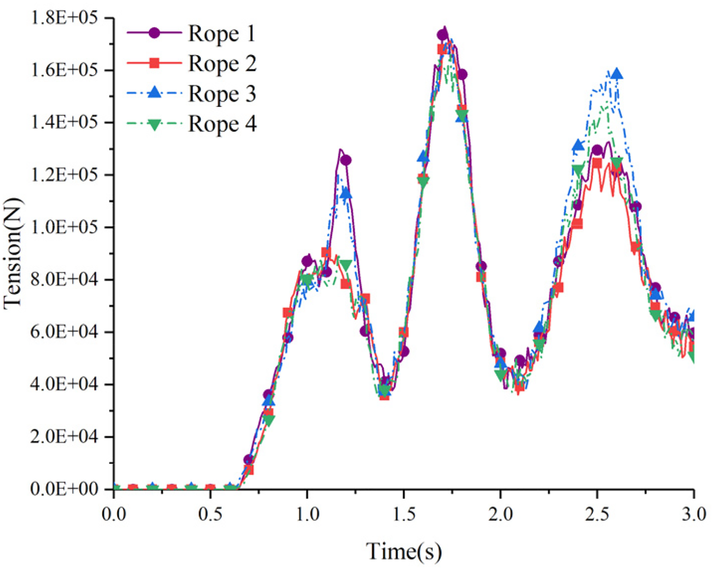
Anchor rope tensions of steel pipe supporting net.
When impacting wire rope supporting and steel pipe supporting nets, the cab velocity changes in vertical direction of the sample nodes on longeron as shown in Figures 32 and 33. During the impact, the cab contacted the net at T = 0.8 s, the kinetic energy of cab started transforming into the elastic potential energy of the inside meshes of fall protection net, and the velocity decreased to 1600 mm/s. The velocity of the cab both decreased to zero at T = 1.7 s within two impacts, which is close to the moment of maximum convex deformation of the outside meshes. Next, the outside meshes began to recover elastic deformation which gave the cab initial velocity to move upward. The buffering effect of the inside meshes caused the cab to decelerate to zero again at T = 2.44 s and T = 2.5 s. In the end, the vertical velocity of the cab impacting wire rope supporting fall protection net finally stabilized at downward 400 mm/s, the vertical velocity of the cab impacting steel pipe supporting fall protection net finally stabilized at downward 960 mm/s.

Maximum deformation of steel pipe supporting net.
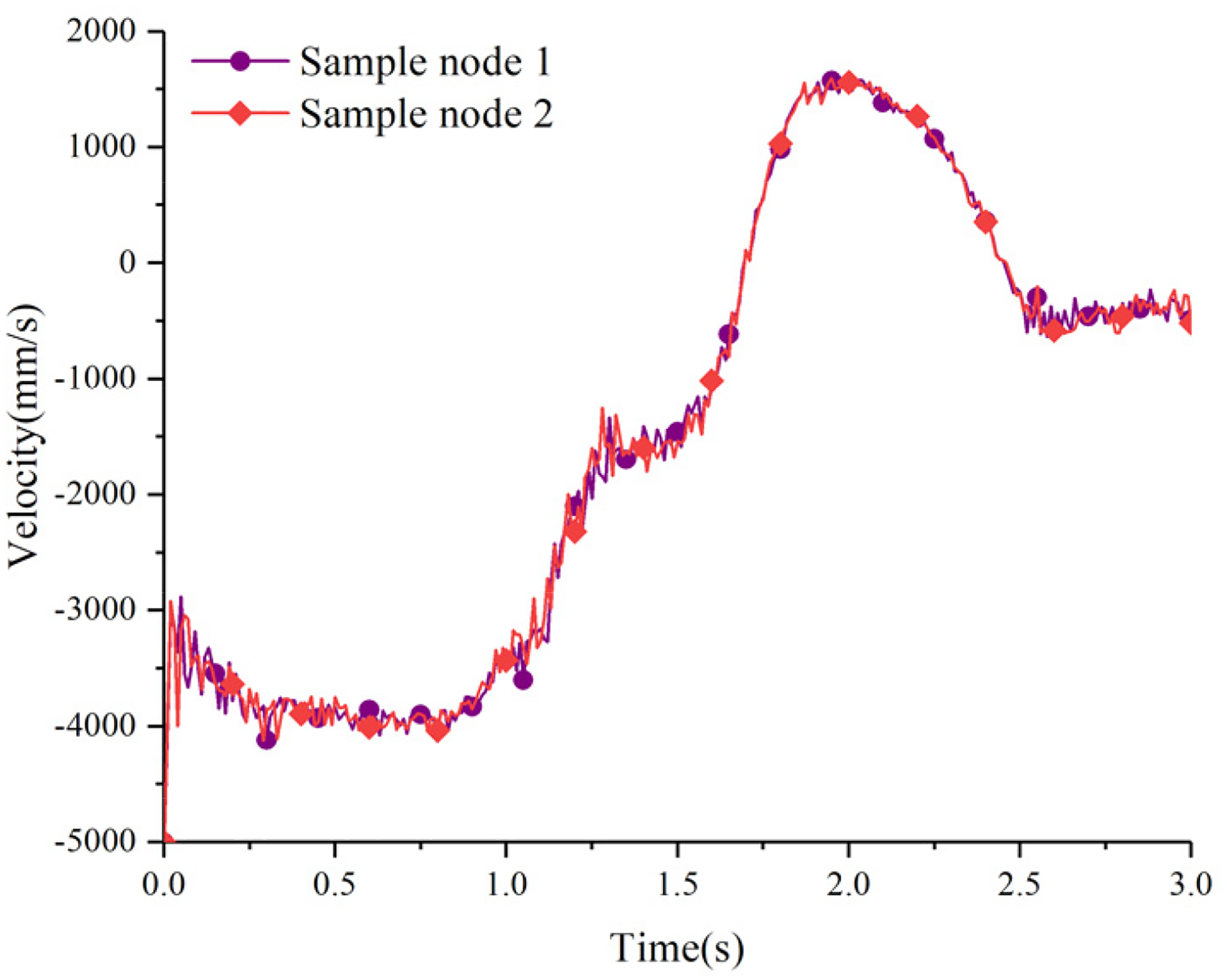
Velocity of cab when impact wire rope supporting net.
When the cab impacted the wire rope supporting and steel pipe supporting fall protection nets, due to the differences in supporting structure and fixing forms, the anchor rope tensions of wire rope supporting fall protection net were less than that of the steel pipe supporting fall protection net and had a better deceleration effect on the cab. However, the anchor rope tension of the steel pipe supporting fall protection net was more averaged, and the structure was more stable. Therefore, it is necessary to use truck impact fall protection net for further comparative research.
Truck impact conditions
The truck model is 8600 mm long, 2500 mm wide, 3500 mm high, and weighs 8.1 ton. In the impact simulation, the whole truck rushed into the fall protection net from the road at an initial velocity of 5000 mm/s. The truck was affected by gravity, and the fall protection net was not affected by gravity during the impact. Accelerometers installed in the cab and cargo can output velocity and coordinate data of the truck. The total impact simulation time is 5 s.
When the truck impacted the wire rope supporting fall protection net, the upper right outside anchor rope had a tensile failure at T = 1.38 s, the fall protection net lost the constraint of upper right anchor, fall protection started shrinking inside. Tension of bottom right anchor rope increased sharply under the impact of truck and had a tensile failure at T = 1.63 s. The two tensile failures of anchor ropes are shown in Figure 34. After two anchor ropes generated tensile failures, the structure of fall protection net was damaged and lost its protective capability.

Velocity of cab when impact steel pipe supporting net.
In the case of the same material parameters of the wire rope, the larger diameter of the steel wire rope means the greater maximum tension it can bear. Considering that the tensile failures of anchor ropes are caused by small diameter, the diameter of the anchor ropes and the supporting ropes were increased from 10 to 20 mm, and the diameter of the wire ropes in four meshes was kept unchanged as 8 mm, then the truck impact simulation was performed again.
After increasing the diameter, the anchor ropes of the fall protection net did not fail when bear the impact of the truck. When T = 1.37 s, the bottom of the left meshes was damaged, and lost the constraint of the bottom left anchor, the fall protection net started shrinking inside. When T = 1.45 s, the bottom of the right meshes was damaged due to the impact. The damages of left and right meshes are shown in Figure 35. After losing the two bottom anchors, the wire rope supporting fall protection net was severely damaged, cannot continue withstanding the impact of truck.

Anchor ropes of the fall-protection net tensile failures.
When the truck impacted the steel pipe supporting fall protection net, the four anchor ropes were not tensile failed, except for small-scale damage in the contact area of the outside meshes. During the impact, the outside meshes and the supporting steel pipe of the fall protection net generated plastic deformation, and the cab of truck was squeezed and collapsed. The impact process is shown in Figure 36.

Meshes damages of left and right meshes.
The changes of anchor rope tensions during the impact of steel pipe supporting fall protection net are shown in Figure 37. The difference between the cab impact and truck impact is that when the truck impacted the fall protection net, it did not contact the inside meshes, and the main deformation area was the outside meshes which caused the tensions of the upper anchor ropes are greater than the bottom anchor ropes. When T = 1.34 s, the upper right anchor rope generated a peak tension of 2.95 × 10⁵ N due to the impact of truck. When the fall protection net already endured the impact of truck, it began to recover elastic deformation, the tension of anchor ropes decreased rapidly. When the convex deformation of the outside meshes reached the maximum at T = 1.79 s, the tension of the upper left anchor rope decreased to 1.19 × 10⁵ N. The truck started moving upward under the push of the outside meshes after T = 1.79 s, the tensions of anchor ropes of the fall protection net were further reduced after losing the interaction with truck. Within T = 2.7 s to T = 4 s, the rear of truck fell to the ground by gravity, and the increases of anchor rope tensions were caused by the drag of truck and the vibration of net itself. Within T = 4 s to T = 5 s, the fall protection net withstands part of the gravity load of the truck and gradually stabilized, the fluctuation of the anchor rope tension gradually decreased.

Truck impact steel pipe supporting fall protection net.
After filtered by Society of Automotive Engineers (SAE) no padding method, the truck velocity changes extracted from the accelerometers is shown in Figure 38. When the truck left the ground, it impacted the outside meshes at a velocity of 5714 mm/s by gravity. The truck did not impact the outside meshes vertically during the impact, the rear of truck moved forward by inertia, which caused the velocity rising and falling of cargo within T = 2.7 s to T = 3.8 s. Finally, the cab of truck stabilized in the outside meshes and the rear of truck stabilized on the ground. The range of velocity fluctuation gradually decreased, and the final velocity tended to 0, which means the deceleration process completed. According to the above analysis, it can be concluded that the supporting structure of the fall protection net should be designed as steel pipe supporting type.

Anchor rope tensions of steel pipe supporting net.
Cumulative protection performance research
The residual deformation and stress of the fall protection net generated in the first impact will inevitably affect its subsequent protection capability. The ability of fall protection net to withstand multiple truck impacts without maintenance or replacement also manifests the cumulative protection performance. In impact simulation, the transmission of residual deformation and stress is achieved by stress initialization.31–33 The end state of first impact is transferred to the beginning state of second impact through prestress. Truck impacts the steel pipe supporting fall protection net is regarded as the first impact. Dynain file is used to initialize the residual stress and deformation of the fall protection net and then the truck impact the prestressed fall protection net again to research the cumulative protection performance of the fall protection net.
The process of the second impact is shown in Figure 39. Because the supporting steel pipe had already generated plastic bending deformation during the first impact, the distance between the outside meshes and the truck was actually been enlarged. During the second impact, the supporting steel pipe and the outside meshes was further deformed. When the cab impacted the outside meshes, the rear of the truck continued moving forward by inertia, which eventually caused the truck to gradually move out of the fall protection net.

Velocity of truck when impact steel pipe supporting net.
The changes of anchor rope tensions during the second impact are shown in Figure 40. At the end of the first impact, the fall protection net was still subjected to the gravity load of the truck. At the beginning of the second impact, the fall protection net was suddenly unloaded after truck withdrawal. And the tension started fluctuating, there were two peaks at the tensions of the upper anchor ropes of the fall protection net. The first peak was generated by the impact of the truck on the fall protection net in driving direction, and the second peak was generated by the squeezing of truck’s gravity load in the vertical direction. The tensions of upper anchor ropes reached the first peak at T = 1.84 s, and the upper left anchor rope generated a tension of 1.23 × 10⁵ N, which is much smaller than the peak of tension generated in the first impact. Next, the truck was pushed upward by fall protection net, the tensions of upper anchor ropes increased again due to the gravity load of truck and reached the second peak at T = 3.67 s, the tension of upper right anchor rope is 9.34 × 10⁴ N. As the truck gradually moved out of the fall protection net, the front of the truck always in contact with the net and squeezed the fall protection net downwards, resulting in the tension increases of the upper anchor rope from T = 4.5 s to T = 5 s.

The second impact of truck on steel pipe supporting fall protection net.
During the second impact, the tensions of bottom anchor ropes showed only one peak, the tension of bottom right anchor rope reached the peak of tension of 9.71 × 10⁴ N at T = 1.53 s, meanwhile the tension of bottom left anchor rope reached the peak of tension of 6.67 × 10⁴ N. Because the truck impacted the upper area of the outside meshes, the bottom anchor ropes were not affected as much as the upper anchor ropes within T = 2 s to T = 5 s, and the tensions of bottom anchor ropes kept fluctuating in a small range.
The velocity changes of the truck during the second impact are shown in Figure 41. The plastic bending deformation of the supporting steel pipe after the first impact increased the distance between the outside meshes and the truck, resulting in the time delaying when truck contacted the outside meshes in the second impact. The truck contacted the outside meshes at a velocity of 5800 mm/s, and then decelerated by the buffering of outside meshes. During T = 3.5 s to T = 5 s, the rear of truck had already moved out of the fall protection net, caused the velocity to increase again by gravity. Although the fall protection net had a decelerating effect on the truck, but it failed to intercept the truck and stop the truck in the net.

Anchor rope tension of steel pipe supporting net.
The coordinate changes of the accelerometer in the vertical direction during the two impacts are shown in Figures 42 and 43. During the two impacts, the truck first moved downwards, then moved upwards, and finally moved downwards, which means it moved downward to impact fall protection net and then bounced up after impact the net, finally descend by gravity. At the end of first impact, the vertical distance between two accelerometers was 1097 mm. At the end of second impact, due to the initial deformation of the fall protection net, the vehicle contacted the net at a lower position, the vertical distance between two accelerometers was 1635 mm, which is larger than the first impact, indicating that the vehicle had turned over in a greater angle. Eventually the fall protection net failed to stop the truck and protect the drivers during the second impact.
Velocity of truck when impact steel pipe supporting net.

Z-coordinate changes of accelerometers during the first impact.
Z-coordinate changes of accelerometers during the second impact.
Results
The design results show that fall protection net with a width of 6000 mm, a span of 6000 mm, a depth of 5196 mm, a mesh length of 150 mm, a mesh type of diamond mesh, a shape of 60° V-shaped, a supporting structure of steel pipe supporting has a better effect on energy absorption and protection effect. The consecutive truck impact simulation results show that the residual plastic deformation and stress of the fall protection net generated in the first impact severely affect the protection performance in the second impact.
Conclusion
The present paper includes a feasible research method and also proposes a complete technical route on the design and simulations of fall protection net set up at the end of truck escape ramp. It was found that finite-element method can be used to design and research cumulative protection performance of the fall protection net and the research conclusions are as follows:
The LINK160, BEAM161 elements, and plastic kinematic, cable discrete beam materials can effectively simulate the structure and material characteristics of the fall protection net, the explicit analysis can be used to simulate the impact between net and dummy and truck. The fall protection net with the following design parameters has a better buffering energy absorption and protection effect: a width of 6000 mm, a span of 6000 mm, a depth of 5196 mm, a mesh length of 150 mm, a mesh type of diamond mesh, a shape of 60° V-shaped, and a supporting structure of steel pipe supporting. Fall protection net needs to be inspected, repaired, and replaced in time after the first impact to ensure the protection performance of the fall protection net for the subsequent impact. The absorbed energy level of protection net and dynamic response are imperfect and need be further discussed in subsequent research.
Footnotes
Declaration of conflicting interests
The authors declared no potential conflicts of interest with respect to the research, authorship, and/or publication of this article.
Funding
The authors disclosed receipt of the following financial support for the research, authorship, and/or publication of this article: Guangxi Natural Science Foundation (grant number: 2020GXNSFAA159173) and Guangxi Key Laboratory of Manufacturing System & Advanced Manufacturing Technology (grant number: 19-050-44-S003), Guangxi Science and Technology Base and Talent Special Project (grant number: 2018AD19349), which are gratefully appreciated.