
Abstract
Low-Vibration Tracks (LVTs) are widely used in subway tunnels for their excellent performance, but the application in heavy-duty railways still requires a lot of feasibility studies. In this study, the statics performance of LVT under different axle loads, load direction, and load position is explored using the finite element software Abaqus. The Timoshenk beam element and nonlinear spring element 3D solid element are used to represent rails, fasteners, and the other track structure respectively. The paper established the finite element model of LVT to study the mechanical characteristics of low vibration track structure under varying loading condition. The applied loads are determined according to the Heavy-Haul Railway Track Structure Design Code. The results shows: (1) The deformation and stress of the LVT structure show a linear relationship with the increase of the axle load. (2) Slab end loading and lateral load are more unfavorable to the stress and deformation of the track structure. When slab end is loaded with vertical load, the vertical load is distributed on four supporting blocks along the longitudinal direction with a ratio of 1:4:4:1, and the lateral direction is mainly borne by two adjacent fastener nodes with the total load proportion of 47% and 47% respectively. (3) The LVT structure can guarantee the safety of static performance under 30 t axle load and the maximum axle load should not exceed 36 t. The paper provides a guideline for the construction and maintenance of LVT structure in heavy haul railway.
Introduction
Heavy-haul railway refers to a railway that meets two of the following three conditions: train traction tonnage above 8000 t, an axle load above 270 kN, and an annual transport volume above 40 Mt in at least a 150 km section of the line. 1 The economic benefits of heavy-haul freight trains with large axle loads are prominent, especially in the construction of new freight railway lines.2–4 Increasing the axle load of the train can obviously improve the transportation capacity and transportation efficiency, while at the same time reducing the unit transportation energy consumption. 5 Solving the problem of matching train axle load and structure is currently still a key issue in the development of heavy-haul railways. 6
Due to the large axle load of heavy-haul trains, during long-term operation the wheel-rail stress is in a high-stress state, and wheel-rail damage and disease will inevitably occur. Examples of such are wheel-rail wear, rail cracks, falling blocks, and wheel scratches, etc. 7 In addition, initial defects can be caused due to the incomplete implementation of the manufacturing process and requirements during the manufacturing process of Rails and wheels. If these defects are not detected in the later inspection process, they can also become a cause of wheel-rail diseases.8–10
Many scholars have carried out a large quantity of related research on the structure type of ballastless track in heavy-haul railway tunnels and related technical research issues, LVT has received increasing attention due to its good performance in vibration reduction.11–15 The LVT structure has a double-layer damping structure with under-rail rubber pads and under-block rubber pads (Figure 1), which can significantly reduce wheel-rail dynamic impact, vibration, and noise when trains pass. As a result, it is mostly used in subway tunnels (Figure 2).

Cross-sectional view of LVT in the tunnel.

LVT construction site in the tunnel.
The lack of research on the static and dynamic characteristics of LVT in the existing literature has hindered the design, installation, and long-term operation evaluation of LVT in the line. Therefore, it is highly necessary to carry out relevant research. Traditional track structure statics mainly focus on the bearing capacity of track structure under train load. 16 With the improvement of mathematical methods and the advancement of computer technology, the calculation models for track structures are constantly improving.17–23 At the same time, the finite element method has also been widely used in related research fields of ballastless track and achieved good results.24–30
The literature24–30 reveals that with the development of science and technology, the existing methods have mainly focused on finite element analysis. However, there is still a lack of relevant finite element analysis and research on LVT, especially regarding the lack of precedent for the study of LVT in heavy-haul railways. Therefore, we take the LVT applied by the Menghua Railway as an example in order to establish a static finite element model of the track structure, and carry out research on the static performance of the track structure under the condition of 30 t axle load. The static characteristics of LVT are analyzed based on the full-scale model static load test of LVT. 31 By establishing the static finite element model of the LVT structure, this paper analyzes the variation law of the static characteristics of the LVT structure at different positions under different train axle loads and lateral loads, and explores the applicability of the LVT structure under higher axle loads, which is useful for providing reference for the design of the track structure in the 30 t axle heavy-duty railway tunnel.
LVT structure statics finite element model
Train load parameters
Based on information drawn entirely from foreign 30 t axle load heavy-haul railway track structure design experience and the content of the “Heavy-Haul Railway Track Structure Design Code” issued in China (in Chinese), in addition to considering the dynamic effect of the wheel-rail’s impact on the track structure, the dynamic load factor is taken as 3.0 (Table 1), the LVT structure bearing the heavy-haul train load is calculated as three times that of the static wheel load, and the single-axis loading method is adopted. 32 Under the comprehensive 30 t axle load condition, the LVT single-stranded Rail bears a vertical load of 450 kN, the lateral load factor is 0.4 times the static wheel load, and the lateral design load is 120 kN. The 32.4, 36, and 42 t axle loads correspond to the 129.6, 144, and 168 kN lateral loads, respectively.
Dynamic load factor.

LVT structural parameters
The static finite element simulation was carried out according to the type of LVT laid in the existing main line tunnel of the Menghua Railway. Menghua Railway, also named Haolebaoji-Ji’an Railway, is a national railway connecting Haolebaoji in Inner Mogolia and Ji’an in Jiangxi province, designed for transporting coal up to 200 million tons every year from northern districts to south districts in China. The LVT structure is mainly composed of rails, elastic type VII heavy-haul railway fasteners, supporting blocks, rubber boots (including rubber pads), track bed slabs, and base slabs. 33
(1) Rail
The heavy-haul railway LVT uses a 60 kg/m standard rail, with the rail density of 7850 kg/m3, and the elastic modulus and Poisson ratio of 210 GPa and 0.3, respectively. The Timoshenko beam element was used for the simulation.
(2) Fastener
The heavy-haul railway LVT adopts the elastic type VII heavy-duty fasteners. In order to fit the actual operating conditions of the fasteners, linear spring elements are used to simulate the lateral and vertical directions, and nonlinear spring elements are used to simulate the longitudinal direction.
(3) Rubber boots
Rubber boots set between the support block and the track bed slab provide good elasticity and can effectively alleviate the wheel-rail dynamic interaction. The solid element was used for the simulation, and the rubber constitutive adopted a two-parameter Mooney-Rivilin model suitable for small and medium deformations.34,35
(4) The tunnel uses the structure of a track bed slab plus base slab, and 20 mm expansion joints are set between the track bed slabs. The support block, track bed slab, and base slab are simulated by solid elements, and the contact between the base slab and the tunnel invert backfill layer are simulated by linear spring elements. The material calculation parameters of the LVT static finite element model are shown in Table 2.
Material calculation parameters of LVT statics finite element model.

Establishment of finite element model
The structural components are simplified in the modeling process in order to reduce the number of nodes and units included in the model, as well as to reduce the memory resources and time required for model calculation. The finite element model of LVT consists of rails (Timoshenko beam element), fasteners (spring element), support block (solid element), rubber boots (solid element), track bed slab (solid element), base slab (solid element). The finite element model of rubber boots, supporting block, and LVT overall structure are shown in Figure 3(a) to (c) respectively.

Finite element model of LVT structure: (a) finite element model of rubber boots, (b) finite element model of supporting block, and (c) finite element model of LVT overall structure.
Setting of calculation conditions
Due to the good elasticity provided by its double-layer elastic supported slab, the LVT can cushion the wheel-rail dynamic impact. However, simultaneously the same double-layer elastic setting will also have a serious impact on the geometry of the track structure. Good geometry can improve the safety and stability of train operation and reduce the maintenance frequency of the track structure. In this section, the stress and deformation analysis of the 30 t axle load applied on LVT track structure is carried out. The condition of the train load on the slab’s end and on slab center is considered, and the variation law of track structure deformation and stress under the vertical load alone, as well as under the lateral- vertical coupled load are explored. After investigating the mechanical properties of LVT structure under 30 t axle load, the changes in static properties and applicability of the LVT structure under higher axle loads are further discussed. The summary of the statics analysis working condition settings is shown in Table 3.
Statics analysis conditions of LVT structure.

Verification of the finite element model of LVT
To verify the reliability of the finite element model of LVT, the full-scale static test 31 on the track structure maximum displacement and maximum tensile stress are selected. The finite element analysis (FEA) results are compared with the experiment results, shown in Tables 4 and 5. For the test of the maximum displacement of rail and support block, the lateral-vertical coupled load is applied to all support blocks on the slab center by a long rail. For the test of the maximum tensile stress of rail and support blocks, the vertical load is applied to a single support block on the slab center by a short rail. The comparison analysis reveals that the finite element analysis results are close to the full scale experimental results and the finite element model of LVT is reliable.
Maximum displacement of rail and support block (unit:mm).

Maximum tensile stress of rail and support block (unit:mm).

Analysis of calculation results of working conditions
Deformation analysis of the loaded LVT structure on the slab center
According to the calculation results of the LVT finite element model under different train loads, the maximum track structure deformation under individual vertical loads, and the lateral-vertical coupled loads are summarized in Table 6.
Maximum track structure deformation under vertical loads and lateral-vertical coupled loads (unit: mm).

According to Table 6, it can be seen that the vertical displacement of the rail under the vertical load of the single train and the lateral-vertical coupled load remains almost unchanged, and presents a linear relationship with the increase of the axle load. Under the vertical load of the train alone, because the bottom of the rail is set at a 1/40 rail cant, the support block is slightly laterally displaced by the lateral force component, and the value of the lateral displacement is small. However, when the lateral design load is applied to the track, the lateral displacement of the support block increases rapidly and exceeds the vertical displacement value. When the axle load is increased from 30 to 42 t, the vertical and lateral displacement of the rail will increase by 40%, but the amplitude of the increase in lateral displacement is greater. As a result, the lateral load has a greater impact on the track gauge maintenance of the LVT structure. Therefore, the rubber boot structure and the supporting block should be fitted well in order to achieve lateral rigidity of the track bed, thereby reducing the possibility of the gauge expansion exceeding its limit and improving the safety of train operation.
Force analysis of the LVT structure loaded on the slab center
The stress distribution of the LVT structural components under different train loads is shown in Figure 4. The LVT stress distribution under 42 t axle load is taken as an example, as the stress distribution of the LVT structure under different axle loads is virtually the same.
Cloud diagram of stress distribution of LVT structural components under different train loads: (a) support block: vertical load acting alone (left), lateral-vertical coupled load acting (right), (b) track bed slab: vertical load acting alone (left), lateral-vertical coupled load acting (right), and (c) base slab: vertical load acting alone (left), lateral-vertical coupled load acting (right)
According to Figure 4, when the vertical load is applied alone, the tensile stress area at the bottom of the support block is largely symmetrically distributed. When the lateral and vertical loads are coupled, the tensile area of the support block is close to the edge of the track bed slab and laterally displaced. The tensile area of the track bed slab and the base slab is consistent with the direction of the lateral force. When the vertical load on the slab center acts alone, the stress state of the support block is more unfavorable. When the lateral and vertical loads are coupled, the stress state of the track bed slab and the base slab is more unfavorable, and the stress growth is faster than when the vertical load acts alone. Because the influence of the chamfered structure of the support block is ignored in the modeling process, there is a stress concentration phenomenon that occurs.
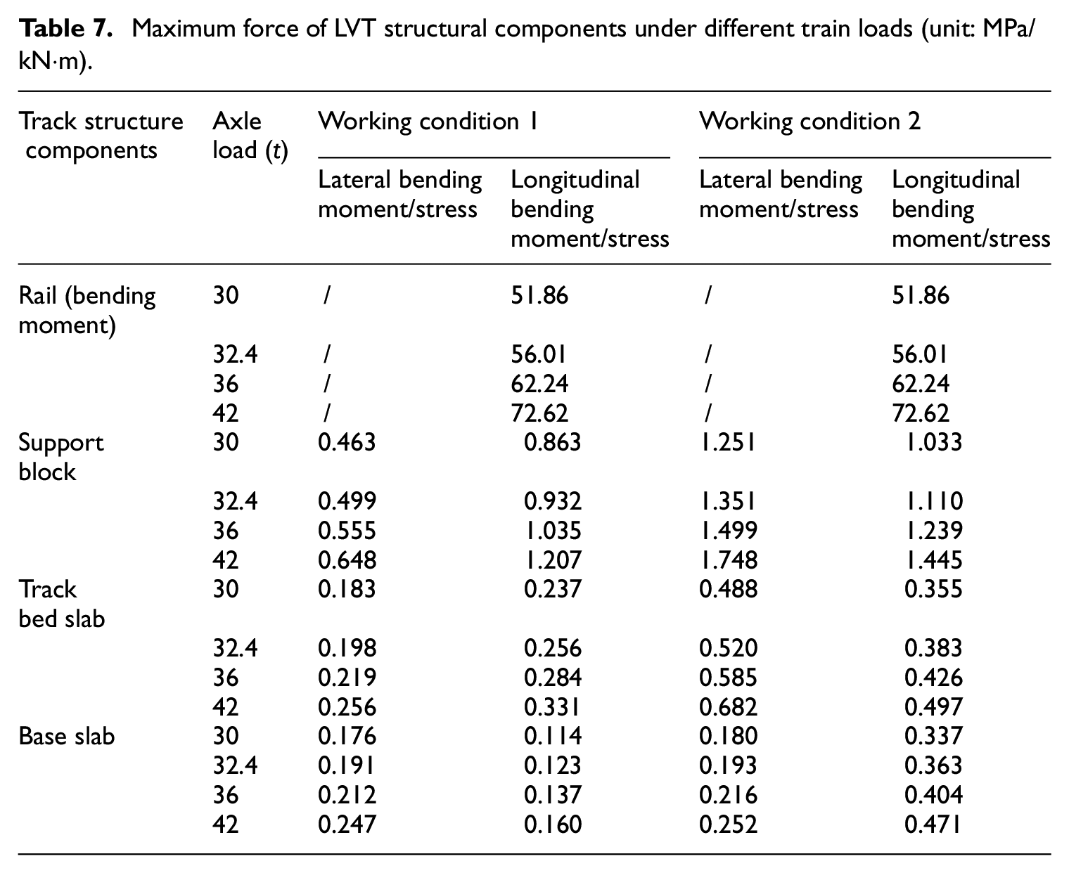
Table 7 shows the maximum stress of LVT structural components under different train loads. According to Table 7, the lateral force has almost no effect on the bending moment of the rail. The lateral and vertical stresses of the supporting block, the track bed slab, and the base slab increase rapidly with the increase of the lateral force, and mainly show a linear growth trend. When the axle load is increased from 30 to 42 t, the stress amplitude of the support block, the track bed slab, and the base slab will increase by 40%, with the lateral stress amplitude increase being even greater. The stress of the track structure is more unfavorable when the lateral and vertical loads of the 30 t axle-loaded train act on the slab. However, the maximum tensile stress of the supporting block, track bed slab, and base slab is still less than the standard tensile strength of C60, C40, and C20 required by the specification. 36
Maximum force of LVT structural components under different train loads (unit: MPa/kN·m).
When the axle load of the train is too large the bottom of the support block may be hollow due to discrete support under the track or improper pouring of concrete when constructing the track bed slab. This may cause the train load to be concentrated in the vertical direction. Currently, the local stress state of the track structure is more unfavorable. To study the law of vertical load distribution of LVT structures under different train loads, the node forces of five groups of fasteners at the load point were extracted for analysis. The vertical load distribution curve of the LVT structure under different train loads is shown in Figure 5. According to Figure 5, the vertical load is largely borne by the loading point and adjacent fastener nodes. The total vertical load at the point of and adjacent fastener nodes is close to 2:1; the lateral load is mainly borne by the loading point fasteners. The ratio of the total vertical load borne at the load point and the adjacent fastener nodes is close to 5:1, so it is extremely unfavorable for the local stress at the loading point on the slab center. Under the vertical load inverted warping will appear in the far-end rail, which may cause the vertical upward displacement of the supporting block. Under the lateral load, the inverted arching phenomenon will appear in the far-end rail, and the reaction force value will gradually increase as the lateral load increases. Therefore, the supporting block may loosen during actual operation.
Longitudinal load distribution curve of LVT structure under different train loads: (a) vertical load distribution and (b) lateral load distribution.
Deformation analysis of LVT structure with slab end loading
According to the calculation results of the LVT finite element model under different train loads, the maximum track structure deformation under individual vertical loads, and lateral-vertical coupled loads is summarized in Table 8. According to Table 8, the vertical displacement of the rail under the effect of the vertical load of the individual train, and the coupled effect of the lateral and vertical load remains almost unchanged. It shows a linear relationship with the increase of the axle load. The vertical displacement of the rail and the supporting block under the independent vertical load of the train is small, but when the track is under a lateral load, the lateral displacement of the support block increases rapidly. Compared with the working condition of the train load acting on the slab, the vertical displacement of the rail and the support block increased by 6% and −20% respectively, and the lateral displacement increased by 40% and 45%, indicating that when the slab end is loaded the lateral deformation of the track structure is more unfavorable .
Maximum track structure deformation under the individual vertical loads and lateral-vertical coupled loads (unit: mm).

Force analysis of LVT structure loaded on slab end
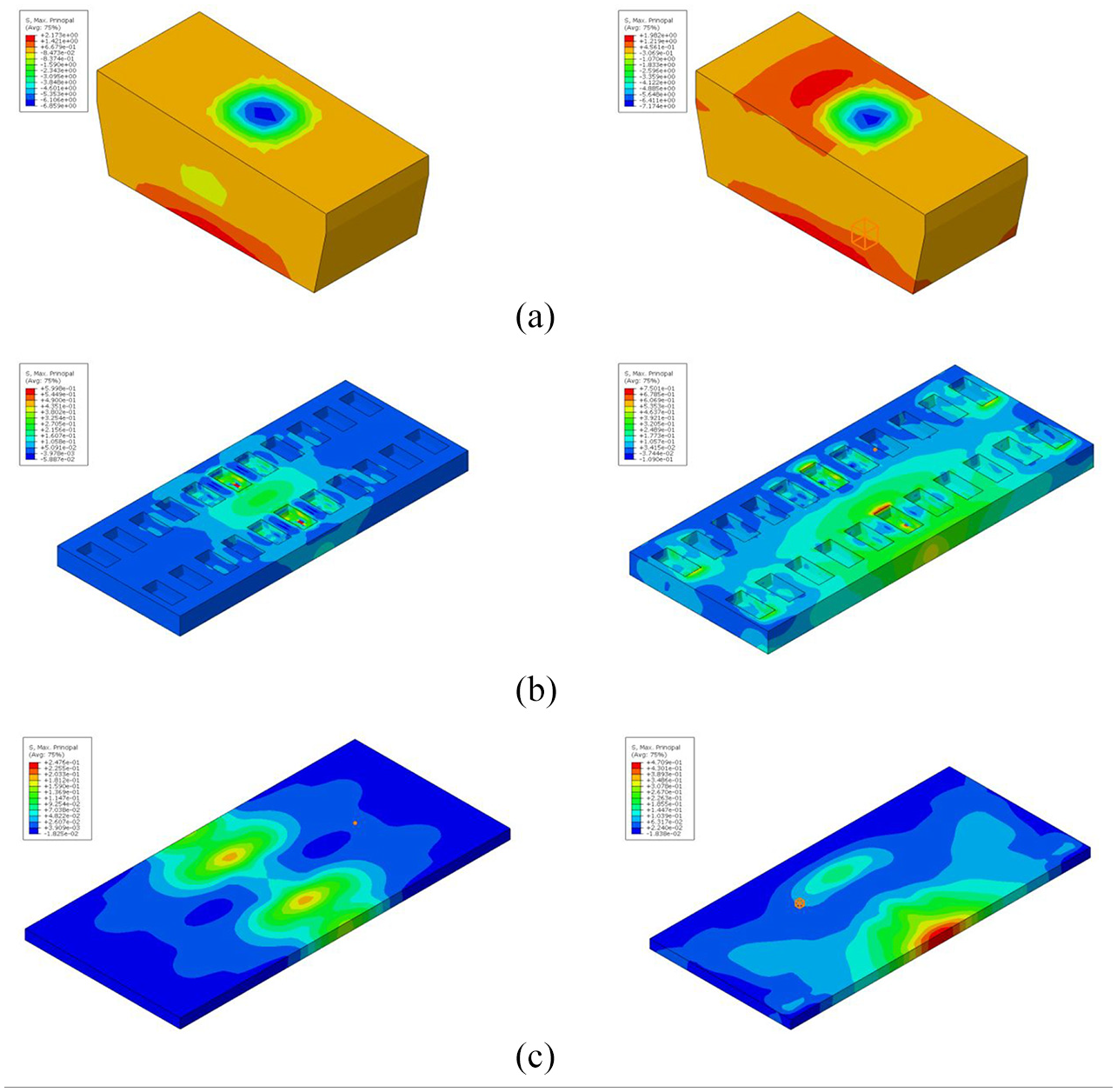
Figure 6 shows the stress distribution of LVT structural components under different train loads. According to Figure 6, when the vertical load is applied alone, the tensile stress area at the bottom of the support block is largely symmetrically distributed. When the lateral and vertical loads are coupled, a concrete tension area appears on the upper part of the support block, and the bottom tension area is offset in the direction of the lateral force. When moving, the tension area of the track bed and base slab is consistent with the direction of the lateral force. When the vertical load acts alone, the stress state of the supporting block is more unfavorable. When the lateral and vertical loads are coupled, the stress state of the track bed slab and the base slab is even more unfavorable. Compared with the load acting on the slab center, the stress state of the track structure loaded on the slab end is more unfavorable.

Cloud diagram of stress distribution of LVT structural components under different train loads: (a) support block: vertical load acting alone (left), lateral-vertical coupled load acting (right), (b) track bed slab: vertical load acting alone (left), lateral-vertical coupled load acting (right), and (c) base slab: vertical load acting alone (left), lateral-vertical coupled load acting (right).
Table 9 shows the maximum stress of LVT structural components under different train loads. According to Table 9, the bending moment of the rail is almost unaffected by the lateral force. Compared with the loading on the slab center, the bending moment of the rail has increased greatly because there is no vertical support at the bottom of the loading point. The lateral and vertical stresses of the supporting block, the track bed slab, and the base slab show a linear growth trend with the increase of the lateral force. When the lateral load is applied, the vertical tensile stress of the track bed slab and the base slab increases significantly. When the axle load exceeds 36 t, the track bed slab and the base slab exceed the C40 and C30 concrete tensile strength required by the specification. When the axle load is increased from 30 to 42 t, the bending moment of the Rail and the stress of the rail structure components increase by 38%. Compared with loading on the slab center, except for the decrease in the lateral stress on the support block, the bending moment of the rail, the longitudinal stress of the support block, the stress of the track bed slab, and the base slab all show an increasing trend. The stress of the track bed slab and the base slab increase by 400% and 530%, respectively. When a 42 t axle load is reached, the stress of each track structure component has exceeded the specification limits.
Maximum force of LVT structural components under different train loads (unit: MPa/kN·m).

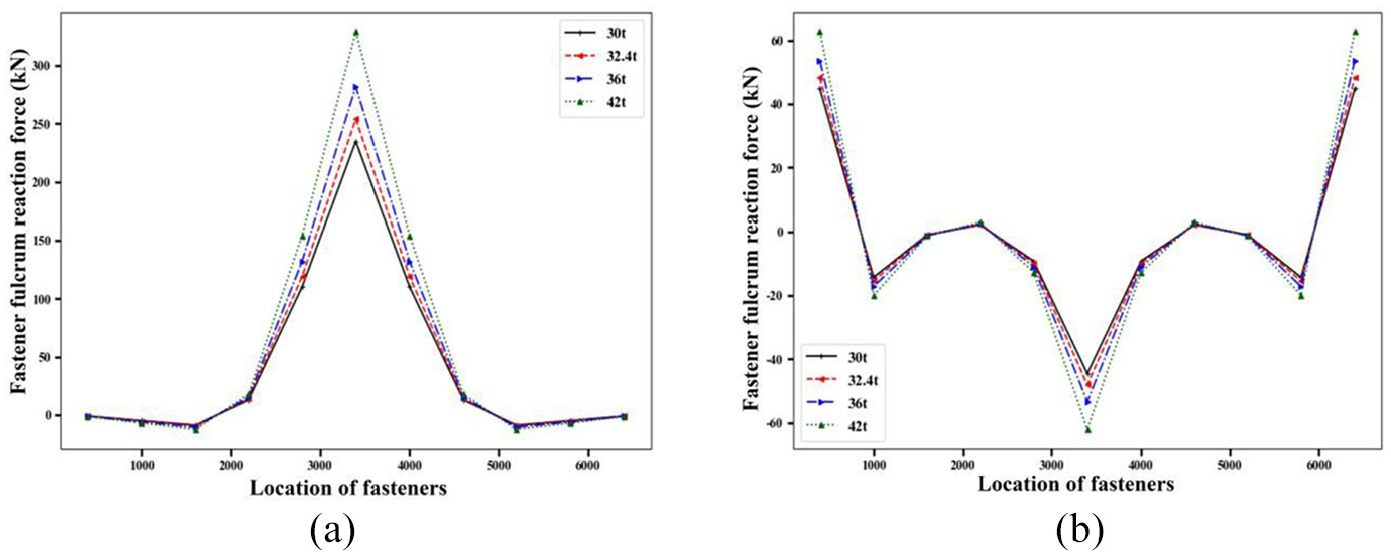
Figure 7 shows the longitudinal load distribution curve of the LVT structure under different train loads when the slab end is loaded. Since the train load is loaded between the sleeper spans when the slab end is loaded, the support blocks on both sides evenly share the lateral and vertical loads, so the peak reaction force of the fastener fulcrum is lower than that of the load on the slab center. The vertical load is distributed on four supporting blocks along the longitudinal direction, with a ratio of 1:4:4:1, and the lateral direction is mainly borne by two adjacent fastener nodes, with the total load proportion of 47% and 47%, respectively.

Longitudinal load distribution curve of LVT structure under different train loads:(a) vertical load distribution and (b) lateral load distribution.
Considering the stress and fastener reaction force, the slab end loading reduces the peak value of the reaction force in comparison to the loading on the slab center. However, the expansion joint between the slab end and the bed slab increases the slab end stress, especially under the lateral load, and the stress of the track bed slab and base slab increase more rapidly.
Conclusions
By establishing the static finite element model of the LVT structure, the mechanical properties of the heavy haul railway LVT structure are studied; the influence of different axle loads, different load direction, and different load positions on the force and deformation of the LVT structure is explored; and the track structure components are studied. The development law of stress and deformation, and the longitudinal distribution law of LVT load along the track are analyzed. The main conclusions are as follows:
The deformation and stress of the LVT structure show a linear relationship with the increase of the axle load. When the axle load is increased from 30 to 42 t, the bending moment of the rail, stress, and displacement of the track structure component increase by about 40%. The lateral load significantly affects the lateral displacement and stress of the track structure, and the stress increments of the track bed slab and the base slab are 284% and 1000%, respectively, when the slab end is loaded.
Slab end loading is more unfavorable to the stress and deformation of the track structure. Under the lateral load, except for the decrease in the lateral stress of the support block, the bending moment of the rail, the longitudinal stress of the support block, the stress of the track bed slab, and the base slab all show an increasing trend. The stress of the track bed and base slab increased by 400% and 530% respectively. As the load on the slab end is shared by the adjacent fasteners, the peak value of the fastener node reaction force decreases, the vertical load distribution ratio under the load point reduces from 2:1 to 4:1, and the lateral load distribution ratio reduces from 67% to 47%.
The LVT structure can guarantee the safety of static performance under a 30 t axle load, but after a certain axle load, the stress and deformation of the track structure will increase. Therefore, according to the requirements of the specification, it is recommended that the maximum axle load design of LVT should be 36 t.
Footnotes
Declaration of conflicting interests
The author(s) declared no potential conflicts of interest with respect to the research, authorship, and/or publication of this article.
Funding
The author(s) disclosed receipt of the following financial support for the research, authorship, and/or publication of this article: The research is financially supported by Hunan Provincial Natural Science Foundation Project (2019JJ40384); the Fundamental Research Funds for the Central Universities of Central South University (Grant 2019zzts873), which is gratefully acknowledged by the authors.
Data availability statement
Experimental data has been presented in the context.