
Abstract
In this paper, a full-scale model of Low Vibration Track was established and three working conditions were applied to a single bearing block; these include: vertical load at the end of the track slab, combination of horizontal and vertical load at the end of the track slab, and vertical load at the middle of the track slab. By applying four times static wheel load to the full-scale model, the relationship between the stress of the track structure and the load under different working conditions was investigated. The corresponding load values were obtained when the track slab and the bearing block reached the axial tensile strength of the concrete. Through the static load test, the weak position of the track structure was found, and the development trend of the crack was obtained. (1) Obtained the maximum stress of the concrete of the track slab at the corner of the bearing block, the maximal stress of the concrete of the track slab, the stress at the bottom of the bearing block, and the stress at the bottom of the bearing block under different working conditions. (2) The horizontal load of the train increased the force of the track slab concrete at the corners of the bearing block. (3) Compared the strain of different location of the track slab and different working conditions. (4) Observed the positions of slight crack and its development trend appeared on track slabs in different working conditions. (5) For the weak part of the track structure, it can be improved by measures such as increasing the thickness of the end of the track slab and arranging stirrups in the track slab around the support block. The research results provide reference for the design, application and maintenance of Low Vibration Track in the heavy-haul railway tunnel.
Introduction
Railway freight is one of the most important modes of transportation, and its high efficiency in dealing with the enormous demands of freight customers has attracted extensive attention in many countries, including the United States of America, Russia, Australia, China, Brazil and South Africa.1,2 One of the most important directions of railway freight development is the heavy-haul railway.3,4 Presently, heavy-haul railway in most countries have a ballasted track structure. However, their large traffic density and volume subject the track to large loads during operation, which accelerates damage to the structure.5,6 In addition, the space inside the tunnel, especially that of long tunnels, is limited, which increases the difficulty of track maintenance and repair. A better choice for long and heavy-haul railway tunnel is the ballastless track, which exhibits a good structural stability and high ride comfort, while requiring less maintenance interventions.7–10 Low-vibration track is a track structure that consists of a steel rail and an elastic bearing block system with matching fasteners and track slab. It is characterised by a low noise level, excellent vibration reduction, easy maintenance and an overall good performance, which makes it suitable for use in long tunnels of heavy-haul railways. The south-central passageway of Shanxi, which was designed and constructed by China, is a long-haul heavy-haul railway channel with a length of 1000 km, a capacity of 10,000 tonnes and a train axle weight of 30 tonnes. The tunnel contains a ballastless track of the low-vibration track type. For the elastic track, many international scholars have mainly conducted research on the structural vibration reduction, rail wear and structure dynamics.
Zeng et al. 11 built two full-scale indoor models to study the vibration behaviours of two kinds of low-vibration track systems for heavy-haul railway using the wheelset dropping impact test method. Kim and Yup 12 elucidated the vibration characteristics of track and vehicle body according to the type of track in tunnel. Liu et al. 13 proposed a novel vibration mitigation slab track plate design and adopted the PolyMAX method for extracting the modal properties, including resonant frequencies, and damping ratios are also determined for both the designed slab and normal slab track plates. Wu et al. 14 investigated the effects of wheel polygonalization on the dynamic responses of a high-speed rail vehicle through development and simulations of a comprehensive coupled vehicle/track dynamic model. At the same time, for the stiff concrete track, some scholars have studied the static mechanical properties of certain track structures. Sadeghi et al. 15 investigated the amount of loads transferred from the rail to the support slabs by conducting a comprehensive experimental investigation in various light and heavy passenger transit lines and derived a mathematical expression for the rail seat load and the loading pattern of concrete slabs. Madhkhan et al. 7 studied the mechanical properties of steel-reinforced concrete precast slab tracks on non-ballasted elasto-plastic foundations, including cracking load, ultimate load and energy absorption. Yang et al. 16 conducted four-point and three-point loading tests on six ballastless track slabs to study the failure modes, mid-span load deflection, crack development and load strains. You et al. 17 studied the gauge-keeping ability influencing factor of elastic bearing block-type ballastless track under heavy load by infinite model calculating and the related indoor test results. However, research on the static mechanical properties and the failure mode of the low-vibration track under train load has not been conducted as extensively.18–20 Taking the study of 30 tonnes axle heavy-haul train as an example, this study explores the static mechanical properties of the low-vibration track under the design load through the static load test. The force condition of the track structure is further clarified by measuring the stress. At the same time, the failure mode of the track structure and the crack development trend are also investigated by applying a larger load, which provides reference values for the improvement, construction and maintenance of the track and the design of low-vibration track to operate a larger-axle heavy-haul train. 21
Overview of full-scale model
In accordance with the design data of the low-vibration track in the tunnel from Yueyang to Ji’an section of the railway coal transportation channel project from Mengxi to Central China, the length of the test track model is designed to correspond to 11 bearing blocks. The bearing block is 680 mm in length, 300 mm in width, 230 mm in height and 160 mm in buried depth and the bearing block is made of C50 concrete. The length of the track slab is 6580 mm, and the track slab is made of C40 concrete. The rail is a 60-kg flat-footed rail section, and elastic VII-type heavy-haul fasteners are used with a spacing of 600 mm. 22 Various mechanical properties on single bearing block and the track structure under different working conditions are compared for the low-vibration track under static load, including the upper and lower surface strain of the bearing block, the surface strain of the track slab and the failure mode of the track structure. Figures 1 and 2 show cross-section of track and the full-scale test model.

Cross-section of track (mm).

Full-scale test model.
Experimental method
Arrangement of measuring points
In this study, strain gauges were arranged as shown in Figures 3 and 4. In order to explore the stress of the track slab around the bearing block, eight track slab strain points (numbered T1–T8) were arranged at the middle position parallel to the four sides of the bearing block and at the four corner points of the bearing block. To investigate the force exerted on the bearing block, 12 strain gauges were used such that two strain gauges were arranged in the middle and at the two opposite ends of both the bearing block upper surface and the lower surface. In Figures 3 and 4, the bearing block upper surface is denoted by the numbers U11–U32, whereas the bearing block lower surface measuring points are denoted by the numbers L11–L32. The strain gauges were attached to the surface using epoxy resin to increase protection and avoid surface damage of the concrete strain gauges.
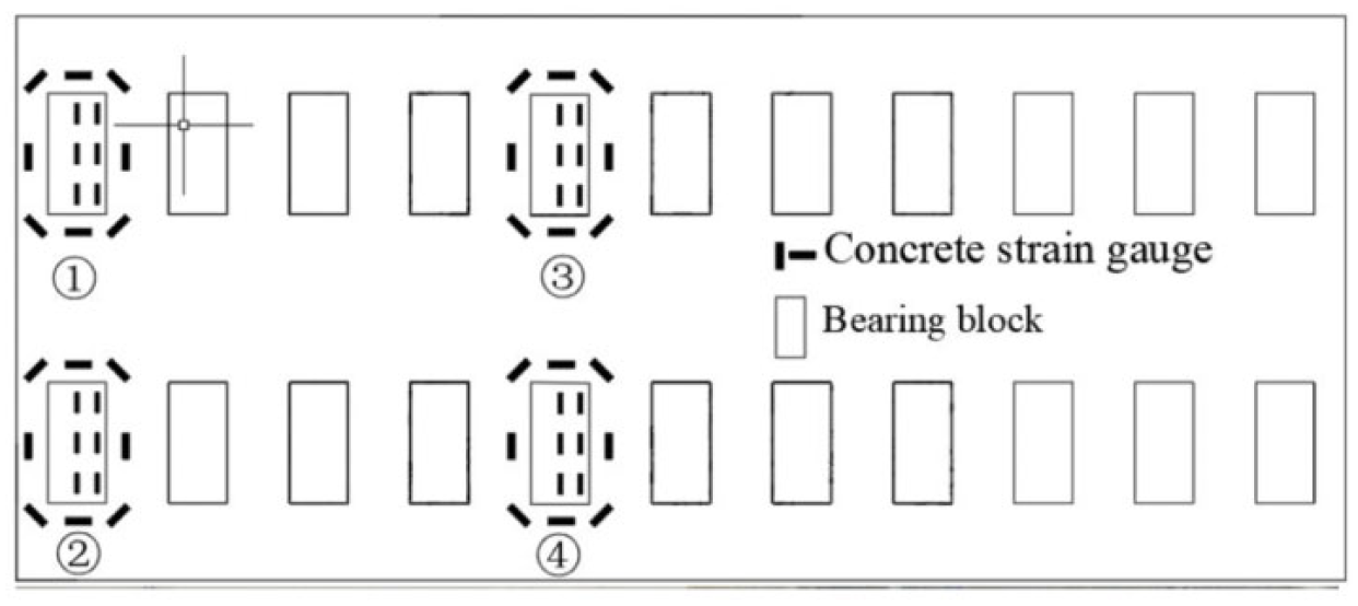
Arrangement of strain gauge at overall.

Arrangement of strain gauge at No. ④ position.
Loading condition
The loading was executed using two different procedures and under three specified working conditions. 17 A brief explanation is as follows:
First loading procedure
In the first loading procedure, loading was performed on a single bearing block, as shown in Figure 5.

First loading procedure.
Taking the train with an axle weight of 30 tonnes (300 kN) as an example, the vertical load-distribution coefficient of the long rail on a single bearing block is 40%, 23 so one times static wheel load acting on a single bearing block is 60 kN. According to the Code for Design Heavy Haul Railway, 24 the vertical design load of the train is three times as large as that of the static wheel load. In this study, the value of 180 kN corresponds to three times static wheel load, while 240 kN corresponds to four times static wheel load.
Second loading procedure
In the second loading procedure, horizontal and vertical loading was performed on a single bearing block, as shown in Figure 6.

Second loading procedure.
The vertical design load of the train is three times as large as the static wheel load and the horizontal design load of the train corresponds to 80% of the static wheel load. 24 Thus, the vertical design load of a single bearing block is 3.75 times of the horizontal design load.
Working condition 1
As shown in Figure 7, under working condition 1, the vertical loading of a single bearing block at the end of the track slab was carried out using the first loading procedure, and it was loaded to 960 kN through the counterforce frame at a constant speed. So, the maximum load on a single bearing block was 240 kN.

Working condition 1.
Working condition 2
As shown in Figure 8, under working condition 2, the horizontal and vertical loading of a single bearing block at the end of the track slab were carried out using the second loading procedure, and it was loaded to 960 kN through the counterforce frame at a constant speed. So, the maximum load on a single bearing block was 240 kN.

Working condition 2.
Working condition 3
As shown in Figure 9, under working condition 3, the vertical loading of a single bearing block in the middle of the track slab was carried out using the first loading procedure, and it was loaded to 960 kN through the counterforce frame at a constant speed. So, the maximum load on a single bearing block was 240 kN.

Working condition 3.
Results and data analysis
The different effects of the horizontal and vertical train load on the mechanical properties of a track structure can be analysed by comparing working conditions 1 and 2. By comparing working conditions 1 and 3, the mechanical properties of the track structure at different positions under the same vertical load can be investigated.
Influence of the track structure on mechanical characteristics
Strain and stress on the surface of the track slab
Table 1 shows a comparison of the concrete strain measured at the surface of the track slab around the bearing block under all the three working conditions, with a vertical load of 180 and 240 kN. As shown in Table 1, the concrete on the surface of the track slab surrounding the bearing block is tensioned under all the three working conditions. The strain (locations T1, T3, T5 and T7) at the corner of the bearing block is larger than the strain (locations T4 and T8) at the long side of the bearing block, while the strain (locations T4 and T8) at the long side of the bearing block is larger than the strain (locations T2 and T6) at the short side of the bearing block. When a vertical train load is applied to the end of the track slab, the strain near the short edge of the track slab (locations T1, T7 and T8) is slightly larger than the internal strain (locations T3, T4 and T5) under working condition 1. When the vertical train load is applied in the middle of the track slab, the strain is symmetrically distributed. The strain at the two corners of the centre line of the track slab (locations T5 and T7) is slightly larger than the strain at the two corners of the edge of the track slab (locations T1 and T3). Comparing the measurements obtained for working conditions 1 and 2, the strain increase at the corner points under the horizontal load of the train is approximately equal to 10%. From the measurements conducted under working conditions 1 and 3, the concrete strain at each position around the bearing block of the middle track slab is smaller than the strain at the end track slab. The average strain recorded for the locations T1–T8 in the middle of the track slab is approximately equal to 78% of that recorded at the end of the track slab.
Comparison of concrete strain on the surface of the track slab, shown in µε.
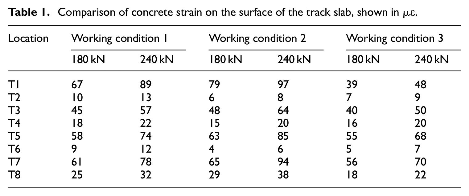
Figure 10 shows the measured concrete strain (at locations T1–T8) on the surface of the track slab around the bearing block, under a vertical load of 180 kN.
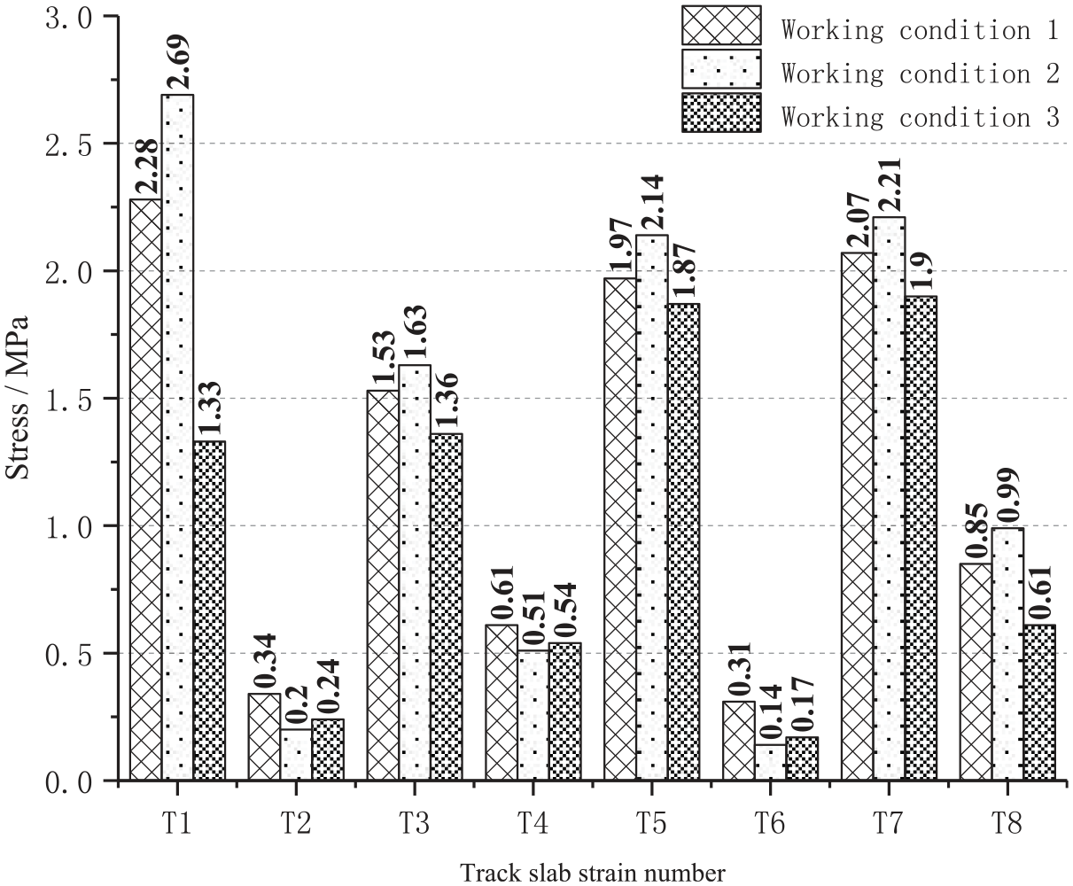
Concrete strain on the track slab surface under 180 kN.
Figure 11 shows the measured concrete strain (at locations T1–T8) on the surface of the track slab around the bearing block, under a vertical load of 240 kN.
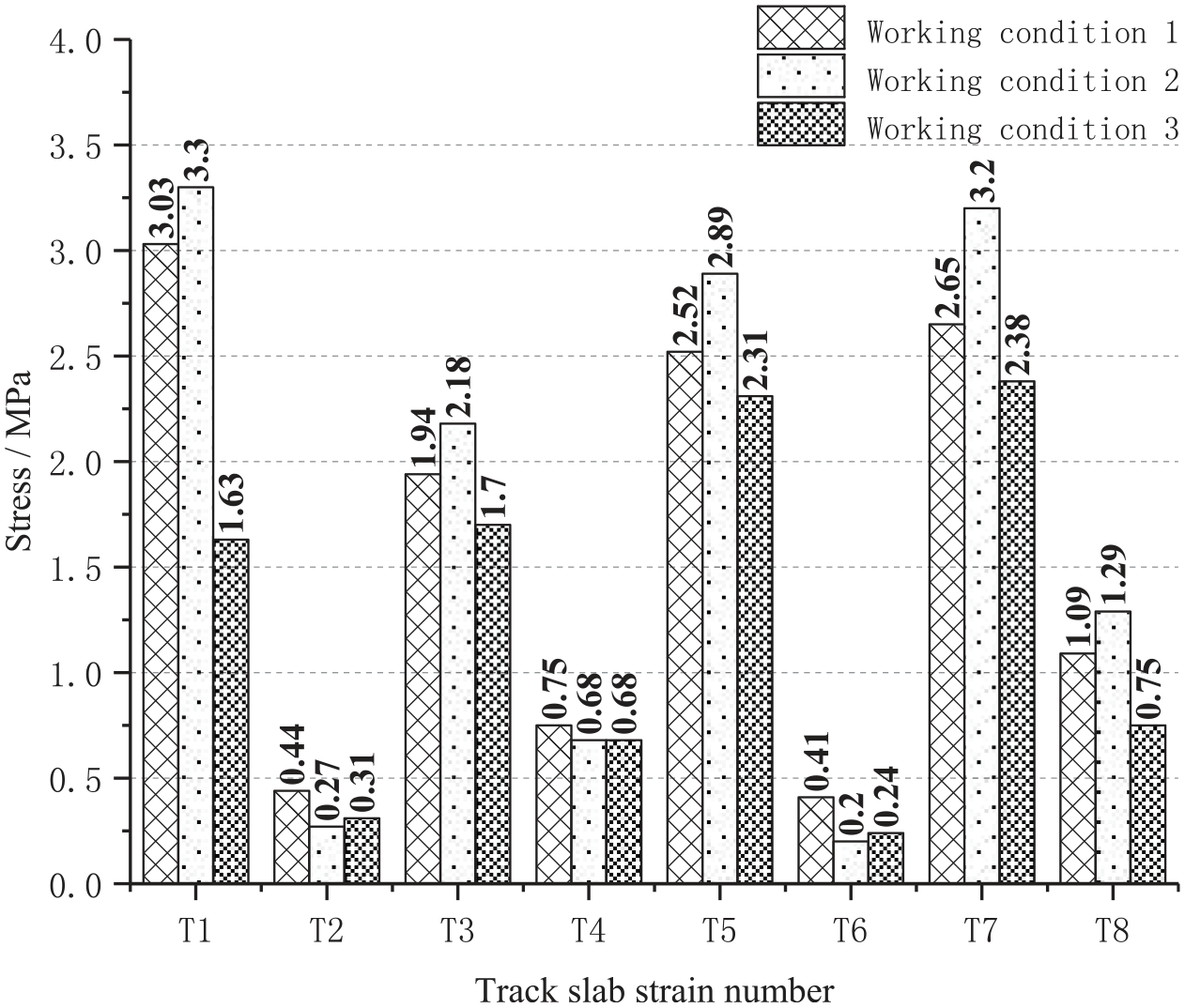
Concrete strain on the track slab surface under 240 kN.
According to the Code for Design of Concrete Structures of Railway Bridge and Culvert, 25 the axial tensile strength of a C40 concrete shaft is 2.70 MPa. When the vertical load is set to 180 kN, the maximal stress of the concrete of the track slab at the corner of the bearing block under working conditions 1, 2 and 3 reached 85%, 100% and 71% of the concrete axial tensile strength, respectively. The stress of the track slab under all the three working conditions does not exceed the axial tensile strength of the concrete. When the vertical load is set to 240 kN, the concrete stress of the track slab at the corner of the bearing block under working conditions 1, 2 and 3 reached 112%, 122% and 88% of the axial tensile strength of the concrete, respectively. As shown in Table 1, the concrete stress of the track slab at the corner of the bearing block under working conditions 1 and 2 reached the concrete axial tensile strength at 196 and 180 kN, respectively. The analysis of the measured data shows that under working condition 3, the concrete axial tensile strength is reached at approximately 294 kN.
Strain and stress on the surface and bottom surface of the bearing block
Previous research has shown that axial compressive strength and axial tensile strength of C50 concrete are equal to 33.5 and 3.1 MPa, respectively. It is a well-established fact that compressive strength of concrete is much larger than its tensile strength. For this reason, the surface of the bearing block was only analysed under the action of 240 kN. Table 2 shows the average values of the concrete strain and stress on the surface of the bearing block (locations U11–U32).
Average concrete strain and stress on the surface of the bearing block.
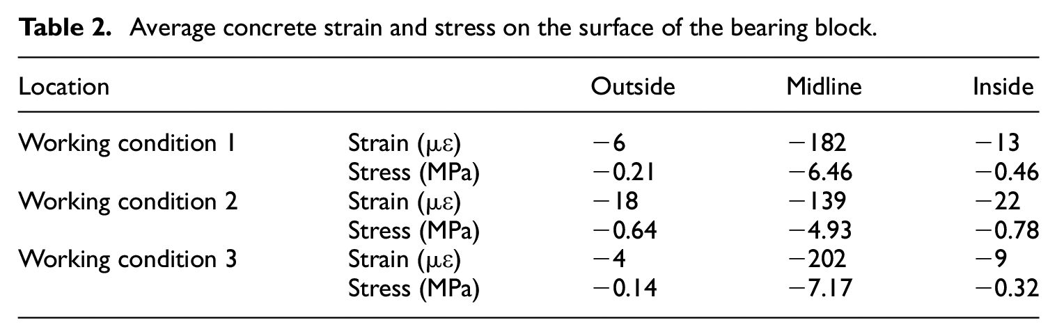
It is worthy to note that the centre line of the short side of the track slab is referred to as being inside (at locations U31 and U32), the centre line of the long side of the bearing block is referred to as the midline (at locations U21 and U22), the end of the track slab is referred to as the outside (at locations U11 and U12) and the numbers in the table represent pressure. The same conditions are valid in Table 3.
Average concrete strain and stress on the bottom of the bearing block.

As shown in Table 2, when the surface of the bearing block was subjected to loading, the compressive strain at the midline was large, while the compressive strain on both of the sides was small. When the vertical load is set to 240 kN, the stress at the midline of the bearing block surface under working conditions 1, 2 and 3 reaches 19%, 15% and 23% of the concrete axial compressive strength, respectively. These values are much smaller than that of the concrete axial compressive strength.
Figure 12 shows the load–strain curves of the bearing block upper surface. When the train load is in the range between 0 and 240 kN, the strain at the upper surface of the bearing block increases linearly with the load under working conditions 1 and 2. Under working condition 3, when the train load reaches 150 kN, the strain slows down as the load increases.

Load–strain curves of the bearing block upper surface.
Table 3 shows the average values of the measured concrete strain and stress (locations L11–L32) on the bottom of the bearing block under vertical loads of 180 and 240 kN.
As seen from Table 3, when the bottom surface of the bearing block is pulled, the tensile strain at the midline is large, and the tensile strain on both of its sides is small. When the vertical load is set to 180 kN, the maximal tensile stress at the bottom of the bearing block reaches 95% of the axial tensile strength of concrete under working condition 1, and 98% under working condition 2. Under working condition 3, the tensile stress reaches the axial tensile strength of the C50 concrete. When the vertical load is set to 240 kN, the maximal tensile stress at the bottom of the bearing block under working conditions 1, 2 and 3 reaches 112%, 113% and 124% of the axial tensile strength of concrete, respectively.
When the train load is in the range between 0 and 240 kN, the strain at the bottom of the bearing block increases linearly with the load. Under working conditions 1, 2 and 3, the strain reaches the concrete axial tensile strength at 188, 185 and 175 kN, respectively.
Cracks on the track slab and bearing block
While increasing the load in the static load test, attention was given to the tensile strain on the surface of the track slab around the bearing block and the tensile strain at the bottom of the bearing block. This section describes the occurrence and development of cracks on the track slab and at the bottom of the bearing block. The crack development trend on the track slab and the bearing block at different positions under the same loading mode was obtained by comparing working conditions 1 and 3.
When the load reached 180 kN, a slight crack appeared at location 1 around the corner of the bearing block at the end of the track slab; however, no cracks were found at other positions. As the load was increased, cracks appeared in the corners of the bearing block in the following order of locations: T1, T5, T7 and T3. At a value of around 200 kN, the cracks gradually expanded into a ‘branch shape’. Slight cracks appeared in the location T8 near the short edge of the track slab. At 240 kN, the ‘branch-shaped’ crack at the corner of the bearing block gradually expanded, and the cracks at locations T1 and T8 extended from the surface of the track slab to its short side, as shown in Figure 13. At the same time, track slab crack at the corner of the bearing block developed along vertical direction, as shown in Figure 14. When the load reached 240 kN, no obvious cracking occurred in the middle of the track slab, and the cracks on the lower surface of the bearing block appeared to be alike with those under working conditions 1 and 3. The crack appeared at the midline of the long side of the bearing block bottom and extended to the middle of the long side of the bearing block, as shown in Figure 14.

Development of cracks on the surface and short side at the end of the track slab.
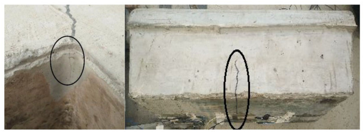
Development of track slab cracks at the corner of the bearing block and cracks at the bottom of the bearing block.
This study takes a 30-tonne axle heavy-haul train as an example. By applying four times static wheel load to the full-scale model, the relationship between the stress of the track structure and the load under different working conditions was investigated. It is verified that the track design meets the static mechanical properties under the design load in the code. In this article, the load–stress relationship under four times static wheel load measured using a 30-tonne axle heavy-haul train as an example can be converted into the load–stress relationship under three times static wheel load measured using a 40-tonne axle heavy-haul train as an example. It can provide a numerical reference for the design of low-vibration track that runs larger-axle heavy-haul trains in the future. At the same time, the failure mode and crack development trend of the track structure were obtained by applying the larger load. The weak positions of the track structure were found, which provides reference values for the improvement, construction and maintenance of the track.
Conclusion
This study investigated the mechanical properties and the crack development trend of a low-vibration track. A static load test of a train with an axle weight of 30 tonne was conducted on a full-scale model. The results of the study are summarised below:
When the vertical load became three times larger than the static wheel load, the maximum stress of the concrete of the track slab at the corner of the bearing block under working conditions 1, 2 and 3 reached 85%, 100% and 71% of the axial tensile strength of the concrete, respectively. The maximal stress of the concrete of the track slab under working conditions 1, 2 and 3 reached the concrete axial tensile strength at values that were 3.3, 3.0 and 4.9 times larger than the static wheel load, respectively.
When the vertical load became three times larger than that of the static wheel load, the stress at the bottom of the bearing block under working conditions 1, 2 and 3 reached 95%, 98% and 103% of the concrete axial tensile strength, respectively. The stress at the bottom of the bearing block under working conditions 1, 2 and 3 reached the concrete axial tensile strength at values that were 3.1, 3.1 and 2.9 times larger than that of the static wheel load, respectively.
The horizontal load of the train increased the force of the track slab concrete at the corners of the bearing block.
When a vertical train load was applied to the end of the track slab, the strain near the short edge of the track slab (locations T1, T8 and T7) was slightly larger than the internal strain (locations T3, T4 and T5) under working condition 1. When the vertical train load was applied in the middle of the track slab, the strain was symmetrically distributed. The strain at the two corners of the midline of the track slab (locations T5 and T7) was slightly larger than the strain at the two corners of the edge of the track slab (locations T1 and T3). Under the same conditions of load and loading mode, the concrete strain at each location around the bearing block of the middle track slab was smaller than the strain at the end of the track slab.
When the vertical load reached a value three times larger than that of the static wheel load, a slight crack appeared on the track slab around the corner of the bearing block at the end of the track slab, and no cracks were found on the other positions in the middle or at the end of the track slab. When the vertical load reached a value four times larger than that of the static wheel load, the cracks gradually expanded into a ‘branch-shape’, while the cracks at positions 1 and 8 extended from the surface of the track slab to its short side. When the vertical load reached a value four times larger than that of the static wheel load, no obvious cracking occurred in the middle of the track slab.
For the weak part of the track structure, it can be improved by measures such as increasing the thickness of the end of the track slab and arranging stirrups in the track slab around the support block.
Footnotes
Declaration of conflicting interests
The author(s) declared no potential conflicts of interest with respect to the research, authorship and/or publication of this article.
Funding
The author(s) disclosed receipt of the following financial support for the research, authorship and/or publication of this article: This study was supported by the Fundamental Research Funds for the Central Universities of Central South University (grant no. 2019zzts624), the support of the High-speed Railway Joint Fund of National Natural Science Foundation of China (grant no. U1734208), the Major Programme of National Natural Science Foundation of China (grant no. 11790283) and the Hunan Provincial Natural Science Foundation of China (grant no. 2019JJ40384).