
Abstract
Aiming at the issues of heavy weight and insufficient structural performance of optical instrument supporting structures in extremely large telescopes, the Wide-Field Optical Spectrograph (WFOS) of the Thirty Meter Telescope (TMT) was taken as a case to study. In order to develop lightweight structures which satisfies the design requirements for mass and stiffness, a design scheme of cylindrical composite shells supporting structure was proposed and their finite element models were developed. A size optimisation and a ply sequence optimisation of the composite structure were carried out. The structures before and after optimisation were evaluated from the aspects of mass, displacement, failure index and fundamental frequency. After the optimised design, the mass of the optimised WFOS cylindrical composite shell structure is reduced to approximately 50%, but its maximum displacement (0.513 mm) and fundamental frequency (8.275 Hz) are nearly unchanged. The study indicates that a cylindrical composite shell structure is an efficient structural form for large optical instruments.
Introduction
An extremely large telescope normally consists of many optical instruments, such as an optical spectrograph, and multiple optical components are assembled on the supporting structure of a spectrograph. The image quality of the telescope is influenced by its structural stiffness. 1 Therefore, it is important to design an optical instrument structure with good mechanical performance. Carbon fibre reinforced polymer composites are an ideal material for lightweight structures with the advantages of low density, small linear expansion coefficient and high specific stiffness. Andrew proved that the mass of a composite structure supporting large telescope optical instruments is much lower than that of a steel structure. 2 At present, three largest telescopes, E-ELT, TMT and GMT, are under construction in the world. Designers of both GMT and E-ELT carried out research on the application of carbon fibre composite materials.3,4
Finite element simulation is a broadly used method for analysing composite structures. Liguori et al. 5 developed a corotational mixed flat shell element for the geometrically nonlinear analysis of laminated composite structures. Chiu et al. 6 established a composite damage model to address intralaminar damage and delamination, for modelling crushing of laminated composites. Dulcey et al. 7 proposed a parametric model of knowledge to allow engineers to make quick simulations of laminated composite structures. Considering progressive damage, Wan et al. 8 performed a finite element simulation to investigate the fatigue life of a full-scale helicopter composite tail structure under multipoint coordinated loading spectrum.
Cylindrical laminated composites are a kind of advanced shell structures because of their light weight and high loading capacity. Great efforts have been made to study their mechanical response and optimisation. Eggers et al. 9 carried out compressive and tensile tests on composite cylinders to evaluate the effects of winding angle, ply sequence and diameter-to-thickness ratio on their mechanical response and failure mechanism. In the design of cylindrical composite shells, optimisation algorithm such as accelerated Kriging metamodel and genetic algorithm were applied to improve their mechanical properties.10,11 Variable-axial fibre layouts of composite cylinders can also be determined during buckling optimisation. 12 Chandra et al. 13 carried out a finite element simulation to verify that the addition of stiffener can avoid the buckling tendency of the thin laminated composite structures. A finite element model was developed by Basri et al. 14 to evaluate deformation and stresses of a rib-reinforced laminated composite wing of unmanned aerial vehicle.
In terms of structural optimisation design, multidisciplinary integrated analysis and finite element methods were applied to the optimisation of optical instruments and their supporting structures.15,16 The ply thickness of the barrel for space remote sensing camera composite was optimised by Xie et al., 17 and a reasonable composite material ply sequence was determined. The composite barrel for a space camera was also optimised by Ren et al. 18 Although optimisation has been widely used in the structural design of space optical instruments, vehicles 19 and submersible, 20 there is little research on the optimisation of composite structures for ground-based telescope optical instruments.
The supporting structure of Wide-Field Optical Spectrograph (WFOS) in Thirty Meter Telescope (TMT) is taken as a case to study. In view of the design requirements for mass and deformation, a scheme of cylindrical composite shell structure was proposed and its mechanical response was analysed by finite element simulation. Size and ply sequence optimisations were applied to the cylindrical composite structure. Mass, displacement, failure index and fundamental frequency of the structures before and after optimisation were compared.
Methodology
Optimisation design method based on OptiStruct
Optimisation design can obtain an optimal structure that meets the optimisation goals under a variety of design constraints. Altair OptiStruct is a structural optimisation design software based on the finite element method. It employs optimisation theories to transform the physical model of a design problem into a mathematical model. A local approximation method is used to solve optimisation problems in OptiStruct, and the steps of a local approximation are as follows:
Analysing corresponding physical problems by using the finite element method;
Determining whether the convergence criterion is satisfied;
Analysing design sensitivity;
Obtaining approximate models and solving approximate optimisation problems by using sensitivity information;
Returning to the first step.
The convergence criteria are satisfied by the time when the change of the objective function value in two adjacent iterations is less than the target tolerance. The optimisation procedure is illustrated in Figure 1.
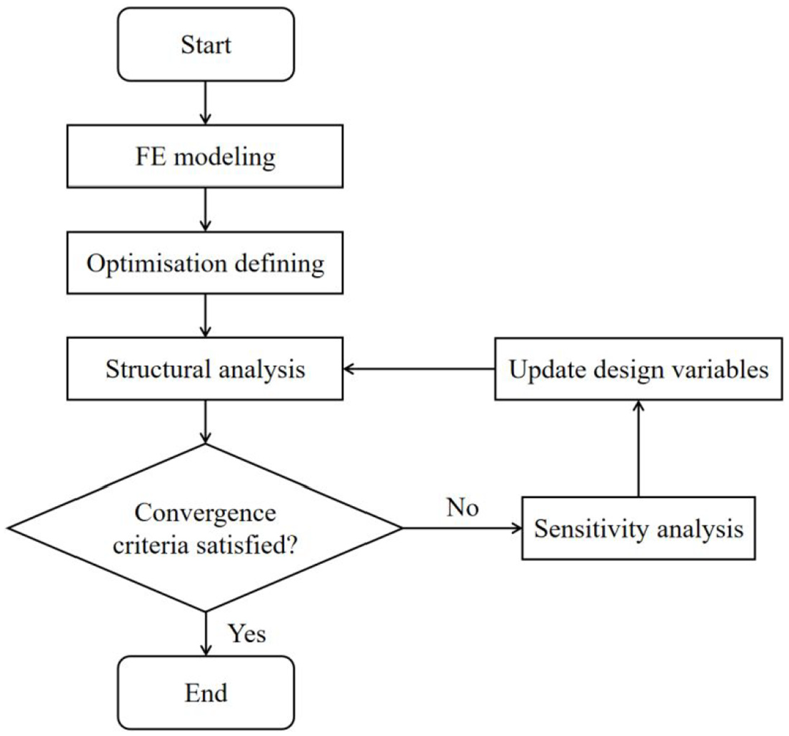
Flowchart of optimisation procedure in OptiStruct.
Size optimisation
The purpose of a size optimisation is to determine the optimal ply thickness of the structure so as to achieve the goal of light weight. The process of size optimisation is shown in Figure 2.

Process of size optimisation.
It can be seen from Figure 2 that during the size optimisation process, the thickness of composite plies of each structural member is taken as the design variables to obtain the optimal number and thickness of plies of different ply angles under the given constraints. The upper limit of the thickness of the ply is given, and the total ply thickness corresponding to each angle is obtained. Then the total thickness is divided by the single ply manufacturable thickness to determine the specific number of plies of different angles. Therefore, the number of plies with corresponding orientation angle after optimisation is determined by equation (1):

where: Nθ– the number of plies with corresponding angle after optimisation;
t θ– the thickness of each optimised ply with corresponding angle;
t 0– thickness of single carbon fibre layer that can be manufactured and processed.
OptiStruct is a structural solver with good function of size parameter optimisation, and it is used to carry out optimisation analysis of the WFOS supporting structure made of cylindrical composite shells. The ply corresponded with optimisation design variables in each optimised area of the cylindrical composite shell structure is established, the manufacturable thickness of each ply is set to be 0.05 mm. The mathematical expression of the size optimisation problem is shown in equation (2):

where: Zi– design variables which refer to the thickness of each composite ply;
F(Z) – target function which refers to the total mass of the structure;
Displacement_xi– displacement of the selected node in the structure;
Frequency – fundamental frequency of the structure.
Ply sequence optimisation
Based on the size optimisation results, in the ply sequence optimisation process, different composite ply sequence combinations can be calculated, and the best ply sequence of the structure under specific working conditions and constraints is obtained. The ply sequence of carbon fibre composite affects the strength of the structure, and a reasonable ply sequence can improve the mechanical properties of the structure. The number of plies corresponding to each angle obtained by size optimisation ignored the ply sequence, so the ply sequence of the structure needs to be further optimised. The mathematical model of ply sequence optimisation is

Where: zi– ply sequence for a given number of plies;
G(Z) – the target function which refers to the natural frequency of the structure.
Design and modelling
Optical system
The WFOS scheme based on X-change belongs to the multi-target slit spectrograph, and 50–80 objects could be observed simultaneously by it. 21 Different observation modes could be realised by switching the plane mirror and grating according to the required resolution of the instrument, and the entire working band is covered by one-time exposure. The main optical design parameters of WFOS are shown in Table 1.
Main optical design parameters of WFOS. 22

As the first light instrument of TMT, WFOS is an imaging spectrograph working under the limitation of atmospheric seeing. 23 WFOS is still in the conceptual design stage at present, and the optical system of WFOS is shown in Figure 3.

Optical system of WFOS. 24
Composition of WFOS supporting structure
The composition of WFOS supporting structure is shown in Figure 4.

Composition of WFOS supporting structure. 25
As can be seen from Figure 4, WFOS is installed on the Nasmyth platform of TMT. The whole instrument can rotate around the horizontal axis to eliminate the image rotation caused by the rotation of the field of view. There are two rotation modes of WFOS, namely normal working mode and fast pointing mode. The rotation speed under normal working mode is 15°/h. WFOS supporting structure consists of two parts, the fixed part of the instrument frame and the rotating part of the main structure. The rotating part is driven by rollers on the instrument frame. Ultra-high Molecular Weight Polyethylene (UHMWPE) material is assembled in the constrained structure to protect the surface of the rotating part. The fixed part and the rotating part are connected by a restraint structure. In order to improve the safety performance of the structure, a damped rubber block is encapsulated in the fixed part to mitigate the influence of earthquake motion on the structure. In summary, following functions are provided by the WFOS supporting structure:
Supporting and connection points for all internal optical components, instrumentation equipment and cables are provided;
A rotating device for eliminating image rotation caused by rotation of the field of view is provided to improve imaging quality;
WFOS optical system is isolated from the deformation of TMT-Nasmyth platform;
WFOS is safely restrained during an earthquake to avoid damage to internal optical components.
Design requirements
The total mass of the WFOS optical components inside is 6109 kg, the imaging quality of the optical system is affected by the mechanical properties of the supporting structure. The structural form and size of WFOS are determined by the internal optical system. The optical path cannot be affected by the supporting structure, and the supporting structure should also have good rigidity and bearing capacity.
The size of the 30 m-level telescope wide field spectrograph is extremely large, and the structure will deform under the action of the telescope and external loads. The development of active compensation technology could effectively compensate for image drift caused by structural deformation and ensure stable performance of the instrument. When the maximum deformation of WFOS is on the order of 1 mm, the active compensation system of WFOS could meet the deformation requirements of the optical system well, which has been proved by Surya et al. 26 Therefore, the design requires that the maximum deformation of the WFOS supporting structure should be less than 1 mm, and the mass of the main structure should be less than 3000 kg. The working frequency of the TMT machine is 2 Hz. 27 To ensure a normal operation of the instrument and avoid any structural damage caused by resonance with the TMT machine, the fundamental frequency of the WFOS structure should not be less than two times that of the TMT machine. In summary, the following factors need to be mainly considered during design of the WFOS supporting structure:
The maximum deformation of the supporting structure should be within the requirements of the WFOS active compensation system;
The supporting structure should have good dynamic performance to avoid resonance with the TMT or internal optical components of WFOS;
The structural light-weight ratio should be improved as much as possible while meeting various design requirements.
Selection of WFOS supporting structure materials
In order to meet the design requirements for mass, deformation and frequency, materials of the supporting structure with low density, low coefficient of thermal expansion (CTE), high specific stiffness and high specific strength28–30 should be selected. Aluminum alloy (LC9), invar (4J32), low carbon steel and carbon fibre composite can be used for optical instrument supporting structures. Properties of the commonly used materials are shown in Table 2.
Commonly used material properties of optical instrument supporting structures.
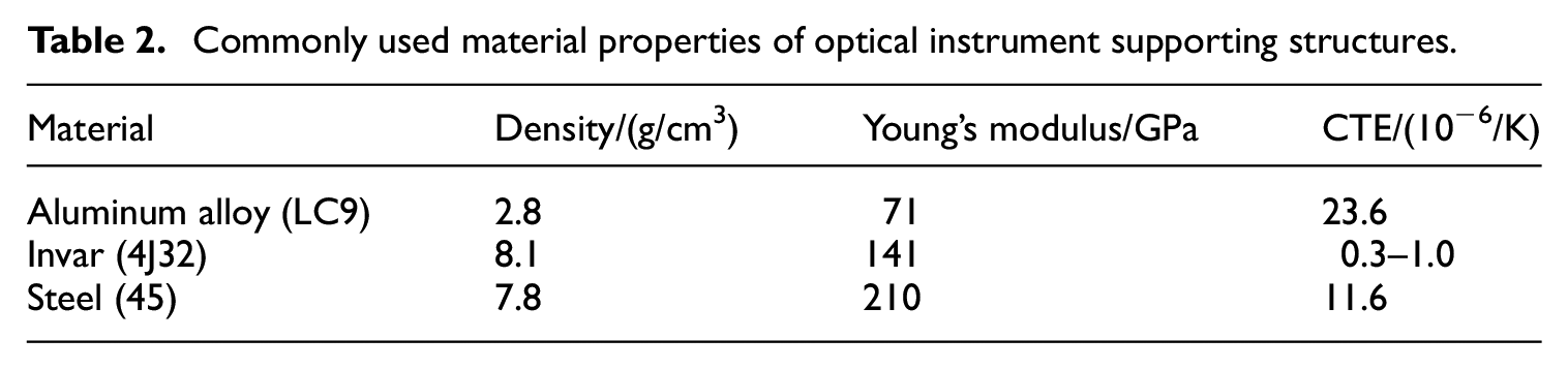
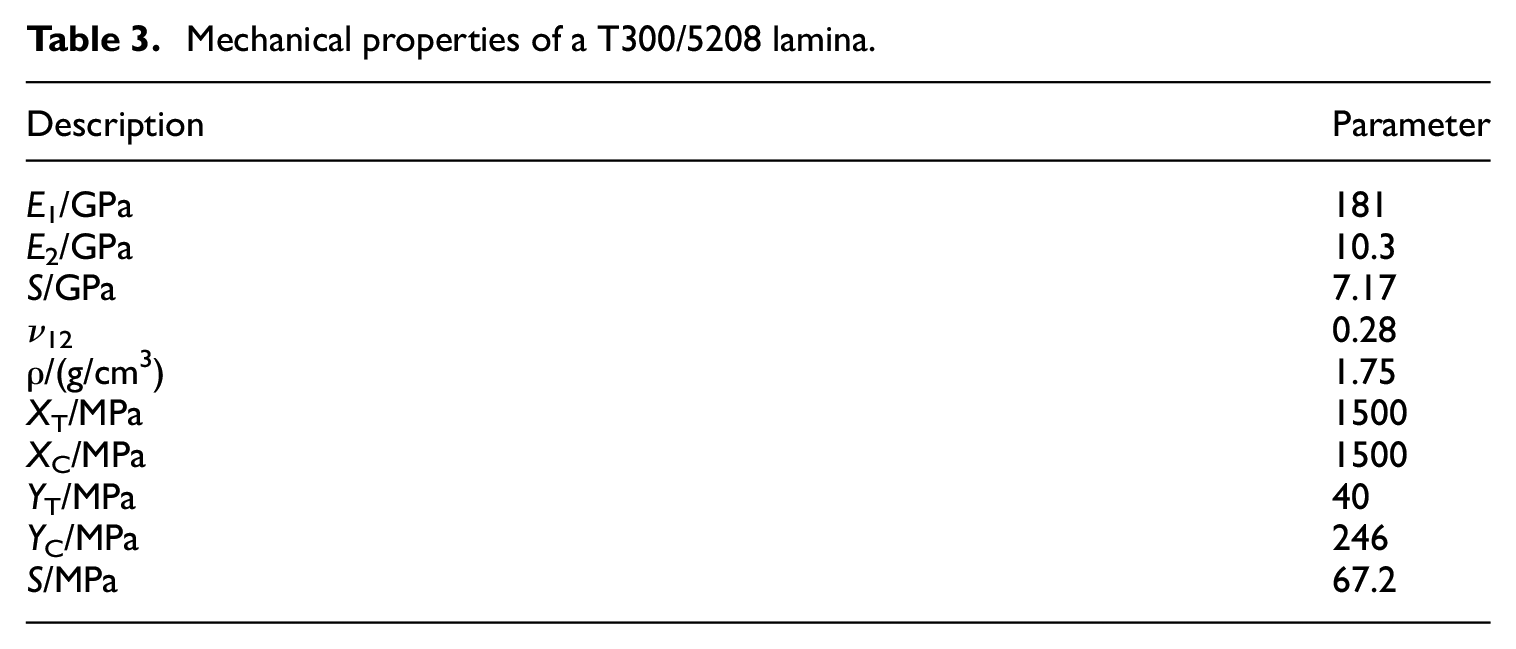
As can be seen from Table 2, invar has the lowest CTE, but the highest density. Aluminum alloy has the lowest density, but the highest CTE. None of the material properties listed in Table 2 is ideal for the WFOS structure. Carbon fibre reinforced polymer composites have super material properties which satisfy the selection criteria of WFOS structure. Therefore, carbon fibre/epoxy composite (T300/5208) is selected as the main material of the WFOS supporting structure. The mechanical properties of a single T300/5208 lamina are shown in Table 3.31,32
Mechanical properties of a T300/5208 lamina.
Design of WFOS cylindrical composite shell supporting structure
A shell structure is one of the most commonly used structural forms because of its good integrity, easy processing and manufacturing and excellent deformation resistance. Therefore, a WFOS cylindrical composite shell structure scheme is proposed here. Nowadays, thin-walled stiffened structures are widely used in aerospace, transportation vehicles, bridges and buildings and finite element methods with advanced higher-order kinematic field were developed for the analysis of stiffened thin-walled structures.33,34 As shown in Figure 5, the form of thin-wall stiffened cylindrical composite shell is adopted as the main structure of WFOS, the corresponding 3D model was established using CAE computer grogram SolidWorks.

Cylindrical composite shell supporting structure scheme of WFOS (unit: mm).
The WFOS structure consists of thin-walled cylindrical composite shell and external stiffened ribs. According to the position of the internal optical system of WFOS and the results of previous parametric studies, the inner diameter of the cylindrical composite shell was taken as 3400 mm, and the thickness of the cylinder wall was taken as 8 mm. In order to increase the torsional rigidity of the cylindrical composite shell structure and prevent the buckling of the cylinder wall, the cylindrical composite shell is designed with multiple circumferential and longitudinal stiffened ribs with the thickness of 14 mm. As mentioned above, the stiffened cylindrical composite shell structure is supported and driven by the driving rotor. In order to reduce the stress concentration at the contact surfaces of the main structure and the driving roller, a ring-shaped shell is designed on the outer edge of the ring-shaped rib to increase the contact area. Considering the engineering practice, the quasi-isotropic stacking sequence [45°/−45°/0°/90°]s was assigned to the cylindrical composite shells. The laminate is symmetrical along the mid-plane to eliminate coupling stiffness, and the ply thickness is 0.25 mm.
Finite element model
In order to create the finite element model of the WFOS structure, its 3D geometrical model was created using SolidWorks. Then it was imported into Hypermesh to carry out finite element meshing. Details on the element types and numbers are listed in Table 4. The established finite element model of the WFOS structure is shown in Figure 6.
Elements of the WFOS finite element model.

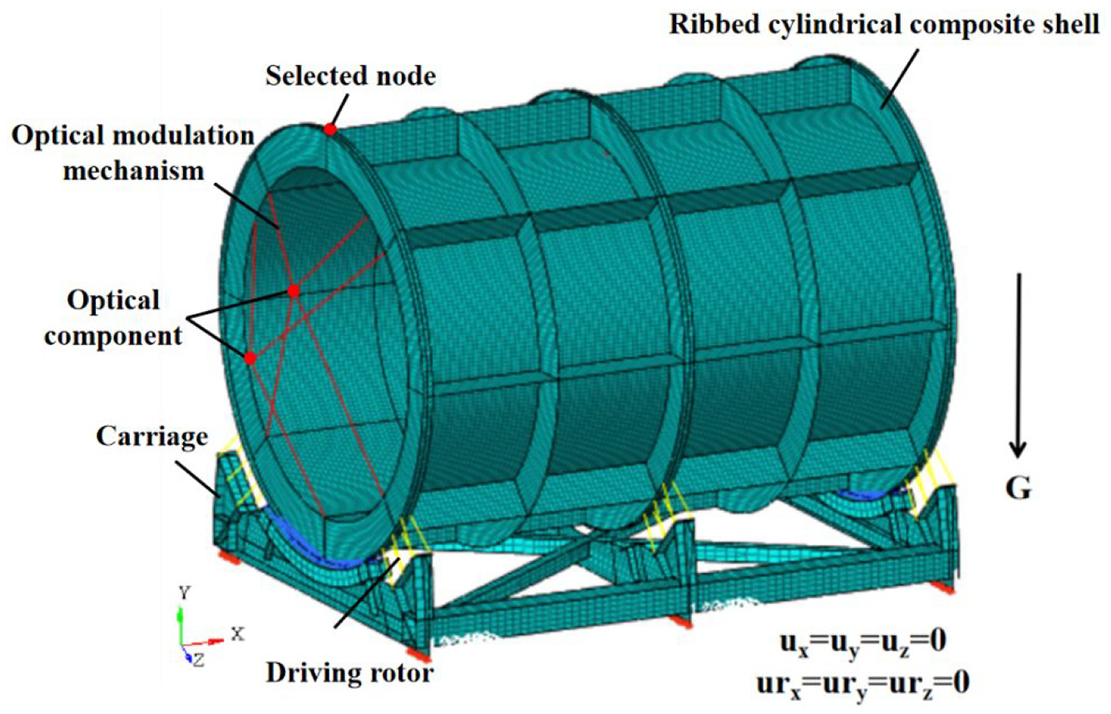
Finite element model of WFOS.
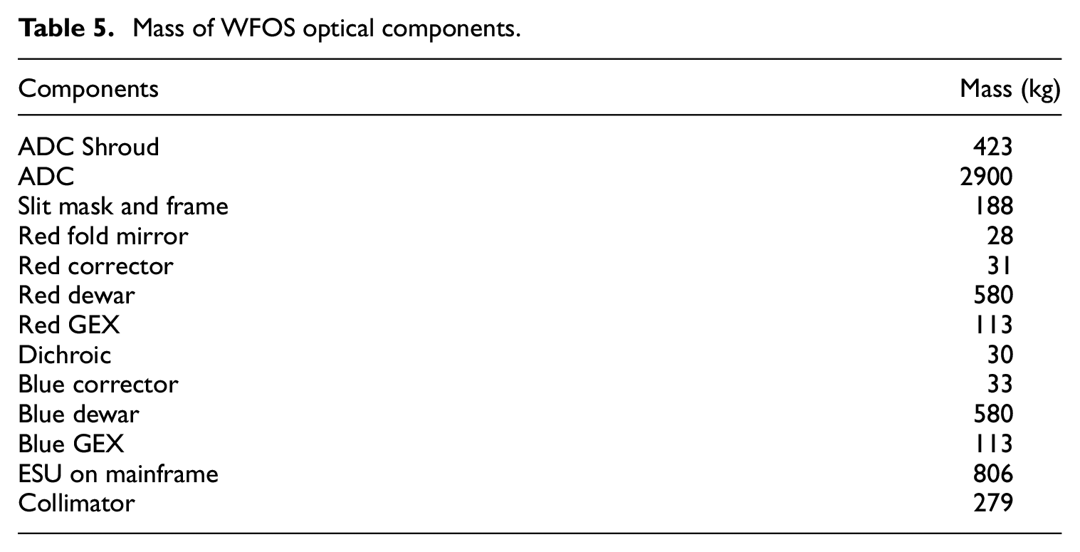
As shown in Figure 6, the wall thickness of the cylindrical composite shell structure is relatively small compared to the overall size of the structure. The cylindrical composite shells and ribs of the WFOS structure are meshed with quadrilateral shell elements (QUAD4) which is defined by four nodes and each node has two translational degrees of freedom. Six connecting plates on the bottom of the carriage are fixed to the Nasmyth platform. All the six degrees of freedom (in red colour) are fully constrained. A gravity load of 9.8 N/kg is applied to the whole WFOS. As shown in Table 4, every optical component of WFOS was simplified into a mass point, and it was assigned the element type CONM2 with a single node and six degrees of freedom. The kinematic constraints were assigned between the mass point and the main structure of WFOS using RBE3 elements. The mass of each optical components is shown in Table 5. It can be seen that the ADC component has much larger mass than others, and therefore those elements connecting to ADC become the regions of interests.
Mass of WFOS optical components.
A mesh convergence study of the WFOS finite element model has been implemented. The determination of the current mesh size considers both the modelling accuracy and the computation cost. The displacement of the node shown in Figure 6 is selected to monitor the convergence analysis because it is within the model’s maximum deformation region. The current mesh is selected when the mesh density is increased to five times of the existing mesh density, but the displacement of the selected node does not change by more than 2%. The current mesh size range of cylindrical composite shell structure is 40–50 mm.
There are some potential sources of modelling errors in the finite element model of the WFOS structure, but their effects on the results are believed to be minor. In order to minimise the element number, some fine details of structural geometry, such as chamfers, holes and driving rollers were not considered. The interactions between the cylindrical shell and the carriage through rubber damper blocks and driving rollers are represented by spring elements, which have independent stiffness in six degrees of freedom. Spring elements are evenly distributed to avoid stress concentrations. The stiffness of each spring elements is determined by the material’s elastic modulus and contact area.
Results and comparative analysis
Mechanical analysis of WFOS supporting structure
Both deformation and modal analysis of the WFOS structure were carried out using OptiStruct. Due to the slow rotation speed of the instrument in normal working mode, the effect of centrifugal force on structural deformation was neglected. Therefore, it was considered as a static finite element simulation. Every 15° rotation angle is taken as a loading condition for analysis. Since the optical components are concentrated in the 0° rotation direction, the 0° orientation is the most unfavorable loading conditions. The deformation diagram under the most unfavorable rotational orientation of the WFOS structure is shown in Figure 7. It can be seen that the maximum displacement of the WFOS cylindrical composite shell structure is 0.554 mm, and the maximum relative displacement of the internal optical components is 0.283 mm. These displacements meets the deformation requirements of the active compensation system. The distribution diagram of failure index and stress of the WFOS structure under the most unfavorable loading condition is shown in Figure 8, Tsai-Wu criteria is selected for material strength assessment. And the first-order vibration mode diagram of the composite WFOS supporting structure is shown in Figure 9. According to the modal analysis results, the first vibration mode of the WFOS structure is the translational mode along the longitudinal direction of the structure, where the bottom carriage is the weakest part. The fundamental frequency of the WFOS structure is 8.15 Hz, which satisfies the no less than 4.0 Hz design requirement. However, the maximum failure factor of the structure is 0.06, which was much lower than 1.0, and the structural mass is 1.93 t. It indicates that the current WFOS structure has a large amount of reserved strength and can be furthered lightened.

Deformation diagram of WFOS (unit: mm).

Distribution of failure index and stress of WFOS: (a) Tsai–Wu failure index distribution, (b) ply stresses in the fibre direction (unit: MPa), (c) ply stresses transverse to the fibre direction (unit: MPa) and (d) ply shear stresses (unit: MPa).

First-order mode shape of WFOS.
Size optimisation
In the initial design of the WFOS cylindrical composite shells, quasi-isotropic laminates with the same thickness are applied to the ribs and cylinders. In order to obtain a more lightweight and robust WFOS structure, the Hyperworks OptiStruct solver is used to optimise the initial design of the WFOS structure.
Since the initial design already met the deformation and frequency requirements, the structural form of the cylindrical composite shell was unchanged and only the thickness of the composite ply was optimised. It can be seen from Figure 8 that the stresses of the shells and ribs vary from area to area, and therefore the wall thickness of different areas can be optimised in accordance to their stress levels. To facilitate the wall thickness optimisation, the WFOS supporting structure was divided to multiple optimisation regions. Theoretically, more regions of the WFOS structure are divided, the better the optimisation results will be. However, considering the practice in manufacturing, the WFOS structure was divided into 11 regions, which are shown in Figure 10.
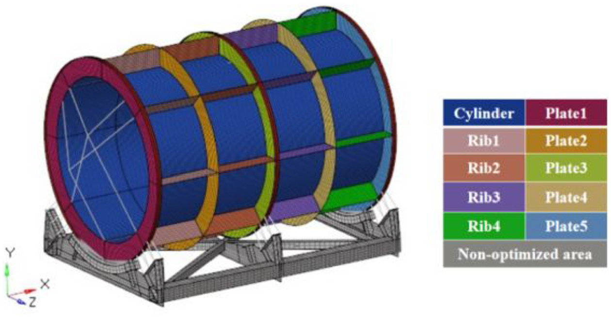
Schematic diagram of WFOS cylindrical composite shell structure region division.
To ensure the integrity and good mechanical performance of the thin-walled composite cylinder, it was considered as an integrated region for optimisation. The circumferential and longitudinal reinforcement ribs are divided into 10 other areas for optimisation. To avoid excessive interlaminar stresses and delamination, the layup of the composite shell structure is set to be symmetrically distributed along the midplane of the laminate. The thickness of a layup orientation cannot be less than 10% of total thickness, and the number of continuous layups cannot exceed four layers. The optimisation computation converged after six iterations. Variations of the mass and fundamental frequency of the WFOS structure along the optimisation iteration are shown in Figure 11.
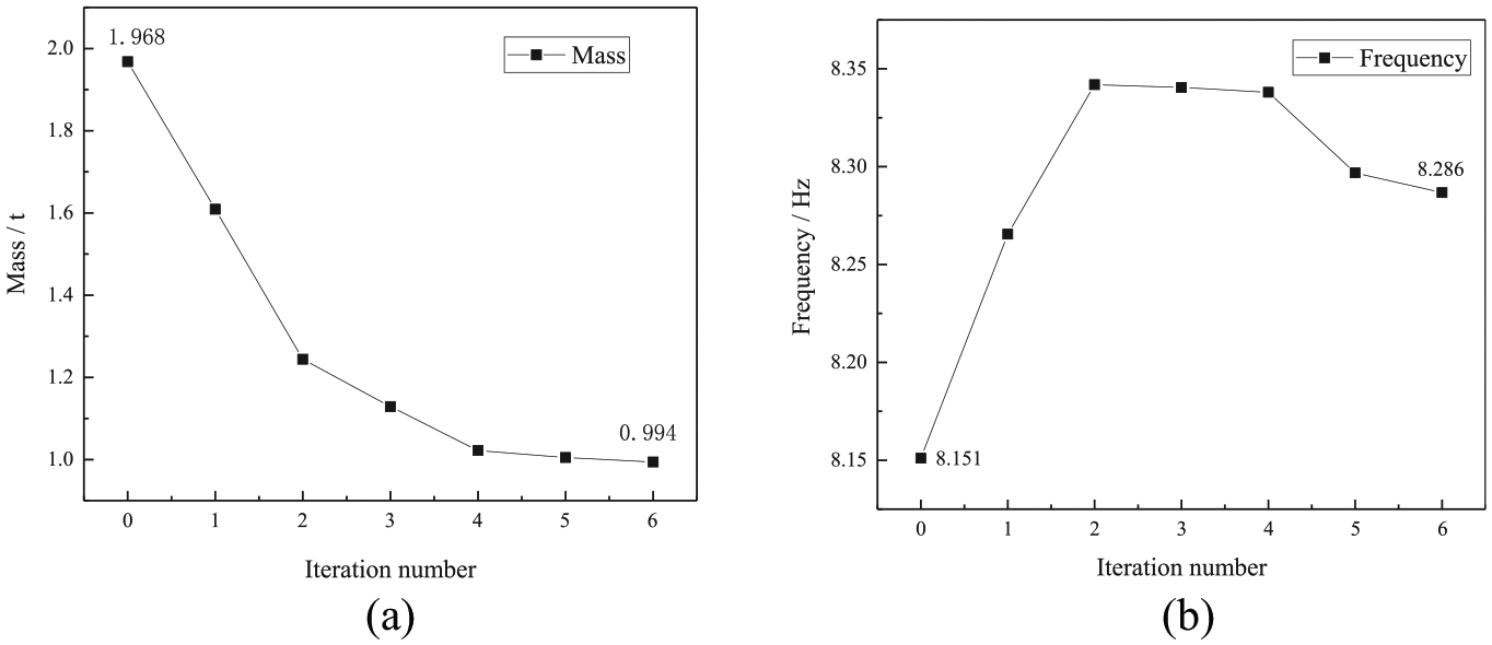
Variations of mass and fundamental frequency along with optimisation iteration: (a) curve of mass on optimisation and (b) curve of frequency on optimisation.
It can be seen from Figure 11 that after size optimisation, the mass of WFOS cylindrical composite shell structure decreased from 1.968 to 0.994 t, which is 49.5% lighter. The maximum displacement of the structure after optimisation is 0.531 mm, which is 4.2% smaller. The fundamental frequency of the structure after optimisation is 8.286 Hz, which is 1.6% higher. The results demonstrate that the mechanical performance of the WFOS structure can still be slightly improved, although its mass was dramatically reduced. It indicates that size optimisation provides a very effective way to find a light-weight cylindrical composite shell structure. The laminate thickness distribution of the WFOS cylindrical shell after size optimisation is shown in Figure 12. The region near the ADC has the largest thickness, 23.7 mm. The thickness distribution of WFOS structure after size optimisation is shown in Table 6.

The thickness distribution of WFOS structure after size optimisation (unit: mm).
Thickness distribution of the WFOS structure.

Ply sequence optimisation
Stacking sequence optimisation of a laminated cylindrical composite shell for obtaining the maximum natural frequency has been demonstrated by Yas et al. 35 In the design of a laminated composite structure, the optimisation of ply sequence is an indispensable step. Not only the mechanical behaviour of the WFOS cylindrical composite shell supporting structure is affected by composite ply sequence, but also the manufacturing process. The purpose of the ply sequence optimisation is to obtain the maximum stiffness of a laminated structure.
Size optimisation results only gave the thickness of laminates, but no specific ply sequence was determined. The optimisation of ply sequence was conducted on the basis of the size optimisation results by employing OptiStruct. The following optimisation constraints were set.
To ensure uniform thickness of plies and improve the manufacturability of the layer, the number of continuous layups are not greater than four layers.
45° and −45° plies have to appear in pairs to avoid tension, bending and torsion coupling and to prevent warpage during the manufacturing process.
The layups are symmetrically distributed along the midplane of the laminate.
After five iterations, the optimal ply sequence of the WFOS composite supporting structure was obtained. The variations of ply sequence along the optimistation iteration is shown in Figure 13. Because the laminate layups are symmetrically distributed, only half of the ply sequence is shown.

Composite ply sequence process of cylinder area.
Since the thickness of the composite shells remains unchanged in the ply sequence optimisation process, the mass of the structure does not change. Nevertheless, the fundamental frequency and the stiffness of the optimised structure increased slightly. Figure 14 shows the variation of the fundamental frequency along with the optimisation iteration.
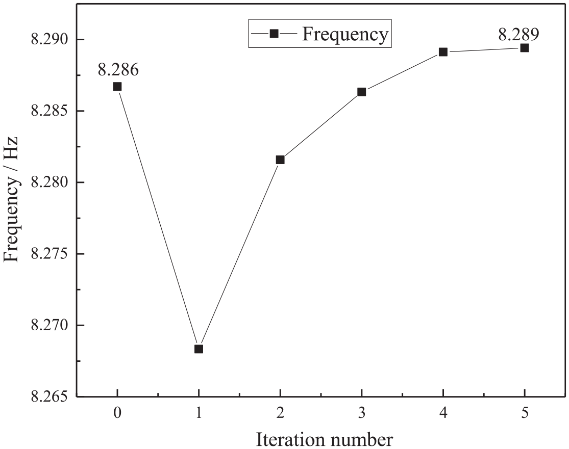
Curve of frequency of WFOS on ply sequence optimisation.
As can be seen from Figure 14, the fundamental frequency of WFOS after ply sequence optimisation is 8.289 Hz, which is nearly unchanged compared with the fundamental frequency before optimisation. The maximum displacement of the structure after ply sequence optimisation decreases to 0.527 mm, which is 0.7% lower than the maximum displacement of the structure before optimisation. It means that the mechanical properties of the structure after the ply sequence optimisation were only improved slightly. The optimal ply sequence of the WFOS structure is shown in Table 7 after six iterations. Among them, the thickness of each ply is 0.05 mm.
Optimised ply sequence of WFOS.

Discussion
The study proposed a structural form of stiffened cylindrical composite shells for large optical instruments. The results demonstrates that the proposed structure very efficient and can satisfy the design requirements for mass and deformation. For such a large optical instrument structure, the following aspects need to be considered to make a lightweight design. First of all, an appropriate structural form needs to be identified according to its load and boundary conditions. For the selected cylindrical composite shell structure in the current study, stiffened ribs were also determined according to the distribution of its internal optical components. Secondly, lightweight materials with high-strength and low-density are favorite candidates. If the preliminary designed structure meets the basic design requirements, a size optimisation can then be conducted straightforwardly. For composite structures, a size optimisation mainly focus on the thickness of each ply. Ply sequence optimisation can then be performed to obtain better material properties. In theory, topology optimisation and fibre orientation optimisation are also very important for a lightweight design. However, considering the constraints of the complicated layout of the WFOS optical components, and the manufacturing difficulties, they are not carried out in the current study.
Mass, fundamental frequency, maximum deformation and failure factors of the WFOS structure are selected as the evaluation indexes of the optimum structure. The first-order mode shapes before and after optimisation are shown in Figure 15. It can be seen from Figure 15(b) that the optimised WFOS structure has obvious local buckling at the plates 2 and 4. Therefore, keeping their ply sequence unchanged, the thickness of each layer is decreased to 0.1 mm, the first three modes of the structure before and after modification are shown in Figure 16. It can be seen that all the frequencies of the first three modes of the optimised structure are higher than those of the structure before optimisation, and the mode shapes are quite similar. The first mode shapes are all translation which are along the long axis of the structure. The second-order mode shapes are all torsion which are around the long axis of the structure. For the third-order mode shape, it can be seen from Figure 16(e) that there is phenomenon of local buckling in the carriage part, while the third-order mode shape of the optimised structure is torsion which is around the direction of gravity. As a result, the structure after size and ply sequence optimisations has better vibration characteristics.

First-order mode shape of initial and optimised design: (a) initial design and (b) optimised design.

First three mode shapes of the initial design and optimised design: (a) first-mode shape of initial design, (b) first-mode shape of optimised design, (c) second-mode shape of initial design, (d) second-mode shape of optimised design, (e) third-mode shape of initial design and (f) third-mode shape of optimised design.
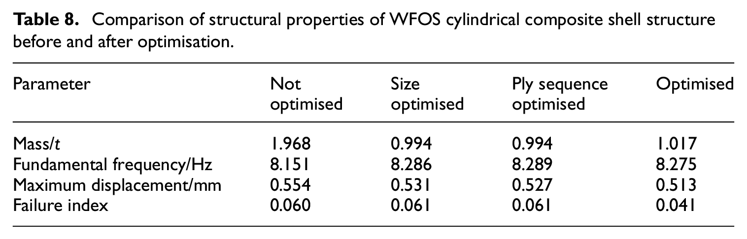
The distribution of displacement and failure index distribution of the initial design and optimised design are shown in Figure 17. The comparison results of mechanical performance of the composite WFOS cylindrical composite shell structure before and after optimisation are listed in Table 8. The maximum displacement of the optimised WFOS cylindrical composite shell structure is 0.513 mm, its fundamental frequency is 8.275 Hz and its Tsai-Wu failure index is 0.041. The results show that both the strength and deformation of the optimised structure meet the design requirements, and have better structural performance than that of the initial structure. The mass of the optimised WFOS cylindrical composite shell structure is 1.017 t, which has a reduction of 48.3%. The purpose of a light-weight design of the WFOS supporting structure is well achieved.

Distribution of displacement and failure index distribution of the initial design and optimised design: (a) displacement of initial design (unit: mm), (b) displacement of optimised design (unit: mm), (c) Tsai–Wu failure index of initial design (unit: MPa) and (d) Tsai–Wu failure index of optimised design (unit: MPa).
Comparison of structural properties of WFOS cylindrical composite shell structure before and after optimisation.
Conclusions
A cylindrical composite shell structure supporting optical instruments in extremely large telescopes has been developed. The size optimisation and ply sequence optimisation were applied to the lightweight design of the structure. The mechanical behaviour of the optical structure before and after optimisation were compared and analysed to verify the effectiveness of the optimised scheme, and the following conclusions are drawn:
It is feasible to design a lightweight cylindrical composite shell structure by performing size and ply sequence optimisations of composite materials.
After the optimised design, the mass of the optimised WFOS cylindrical composite shell structure has been reduced to nearly half of its initial mass. While the design requirements for deformation and fundamental frequency are still satisfied.
A cylindrical composite shell structure is an efficient structural form to support large optical instruments in extremely large telescopes.
Footnotes
Acknowledgements
The authors gratefully acknowledge the support of Matthew Radovan who was the Project Manager during the MOBIE Mini studies and the project Chief Engineer during the Exchanger trade study.
Declaration of conflicting interests
The author(s) declared no potential conflicts of interest with respect to the research, authorship, and/or publication of this article.
Funding
The author(s) disclosed receipt of the following financial support for the research, authorship, and/or publication of this article: National Natural Science Foundation of China (U1831105, 12072192, 11603054) and CALT201808.