
Abstract
To study subway turnouts’ adaptability to steep gradients, a finite element model of a metro No. 9 simple turnout was established. The main works include: (1) The train’s most unfavourable loading condition was modelled. (2) The turnout’s longitudinal displacement and stress were analysed with different gradients under the train braking load, temperature change load and a combination of the two, to determine the structure’s safety and stability under the most unfavourable working conditions. (3) The turnout structure’s cumulative longitudinal deformation under reciprocating load was studied. Both a fastener longitudinal resistance-displacement experiment under reciprocating load and a numerical simulation of No. 9 turnout modelled by the finite element modelling software, ANSYS, were carried out to study the gradient’s influence on the turnout’s longitudinal mechanical characteristics. (1) The turnout’s longitudinal displacement and stress increase linearly with an increase in gradient and temperature change, both of which are unfavourable to the turnout structure. As the gradient increases from 0‰ to 30‰, the longitudinal stress and displacement increase by more than 10%. (2) The turnout’s rail strength and displacement on a 30‰ slope under the most unfavourable load conditions are within the specification limitations. (3) Under reciprocating load, the fastener longitudinal stiffness decreases and the maximum and residual longitudinal displacement of the switch rail increase; an increased gradient intensifies these effects on the turnout.
Introduction
Railway turnouts are railway line intersections and constitute weak links in railway tracks.1–3 It is a special structure with difficulties in technical features. Sometimes when the train runs on the track where there is a change in temperature, excessive force and deformation of the rails in the turnout area are prone to occur which may cause turnout diseases such as rolling of switch rails, switch jamming and excessive deformation of spacer and connecting bolts. Moreover, with long rail, it is easy to produce uneven crawling phenomenon on the long ramp, and this will be hindered by the turnout, thus, leading to more complex stress and strain on the turnout section, which will, in turn, affect the turnout’s geometric smoothness and stability, as well as shorten the service life of the turnout structural components. Therefore, compared with the main line, the current specification is more strict on a turnout’s maximum allowable laying slope 4 ; the maximum slope should be 30‰ on the main line and 35‰ on difficult sections, whereas turnouts should be located on slopes with a gradient of no more than 5‰, and no more than 10‰ on difficult sections. While, due to topographical limitations and geological conditions, turnouts on some track lines must, be installed on slopes with gradients exceeding 10‰. Globally, there is no practical experience in laying, maintaining and operating steep-slope subway turnouts. Thus, steep-slope turnouts’ safety and stability under train operating conditions need to be demonstrated. 5
Many studies have been carried out on turnout forms and parameters,6–10 from which No. 9 to 12 turnouts are the most common. Hence, turnouts with flexible switch rails and a rigid frog were recommended as the main forms in China’s metro system. Gao et al. 11 used a finite element method to study the influence of turnout number, connection form, intermediate straight-line length and ballast bed longitudinal resistance on turnouts’ mechanical characteristics. There are also many studies of turnout dynamics. Xu et al.12–14 developed a numerical programme to predict rail wear on turnout sections. Ma et al. 15 studied the main causes of rolling contact fatigue on the turnout rail surface. Chen et al.16,17 established a vehicle–turnout–bridge dynamic analysis model, using a finite element method, to study the dynamic characteristics of the coupling system. At present, there are few studies of turnouts on steep slopes. Khalil and Metwally 18 studied the influence of longitudinal gradients on the railway turnout fastener system’s performance and proposed ways to reduce rail wear and damage to elastic clips. Hou et al. 19 studied the train-turnout system’s dynamic response when the turnout was set on a slope by establishing a spatial coupling model of the train, turnout and slope. Yan et al. 20 and Zhang et al. 21 studied the gradient’s influence on the stress and deformation of Continuous Welded Rails(CWR) turnouts on long ramp bridges under different working conditions. The results show that higher gradients increase the stress and deformation of CWR turnouts on bridges.
The above research has several issues. First, it generally considered ballasted track beds, while China’s metro system mostly adopts ballastless, monolithic track beds; Though conclusions drawn from ballasted track studies are related to slab tracks to a certain extent, the calculation results of the two kinds of track lines are not completely identical due to the inconsistency of longitudinal resistance composition of ballasted track and ballastless track. Second, uniform load was used to simulate train load,22–24 but for turnout structure, a concentrated load can better reflect stress and displacement behaviour. Third, the turnout structure’s longitudinal displacement and stress behaviour when the train passes through have not been analysed and described clearly. Due to subway trains’ light axle weight, it has been possible to implement turnouts on steep slopes and maintain high train traffic frequency provided that the structure’s safety and stability are verified.
This paper is to study subway turnouts’ adaptability to steep gradients. By establishing a finite element model of a No. 9 lateral turnout, the turnout structure’s longitudinal displacement and stress behaviour under different working conditions were analysed, and the safety and stability under various working conditions were checked and calculated to explore the feasibility of laying subway turnouts on steep slopes. Considering the turnout’s cumulative longitudinal displacement effect under cyclic load, the relationship between the turnout gradient and the cumulative longitudinal displacement of the switch rail was analysed.
Materials and methods
The finite element modelling software, ANSYS, was used to create a numerical simulation of a No. 9 simple turnout. First, the train’s most unfavourable loading condition (as described below) was modelled. Then, the turnout’s longitudinal displacement and stress variation behaviour was analysed with different gradients under the train braking load, temperature change load and a combination of the two, to determine the structure’s safety and stability under the most unfavourable working conditions. Finally, the turnout structure’s cumulative longitudinal deformation under reciprocating load was also studied.
Analytical model
Using actual cross-sectional attributes, variable cross-section beam elements were used to model the turnout’s 60AT switch rails and the 60 kg/m stock rails. Solid elements were used to model the monolithic concrete bed and sleepers. To fully analyse the fastener’s three-dimensional stiffness, its vertical and transverse stiffness were simulated by linear springs, and its longitudinal resistance by nonlinear springs. Nonlinear springs were also used to simulate the rail joints between the switch heel and the closure rail and between the rigid frog toe/heel and the connected rails. The rails’ transverse and torsional deformations at both ends of the joint were synchronized. Fillers were arranged at the switch heels and were simulated by nonlinear elements. The above components’ design parameters are shown in Table 1.
Calculation parameters of the analytical model.

To study the changes to the turnout’s longitudinal stress and displacement when a train passed through the turnout section, the model included an additional 150 m of track at both ends of the turnout area. The schematic diagram of the finite element model and the components of the turnout are shown in Figure 1.
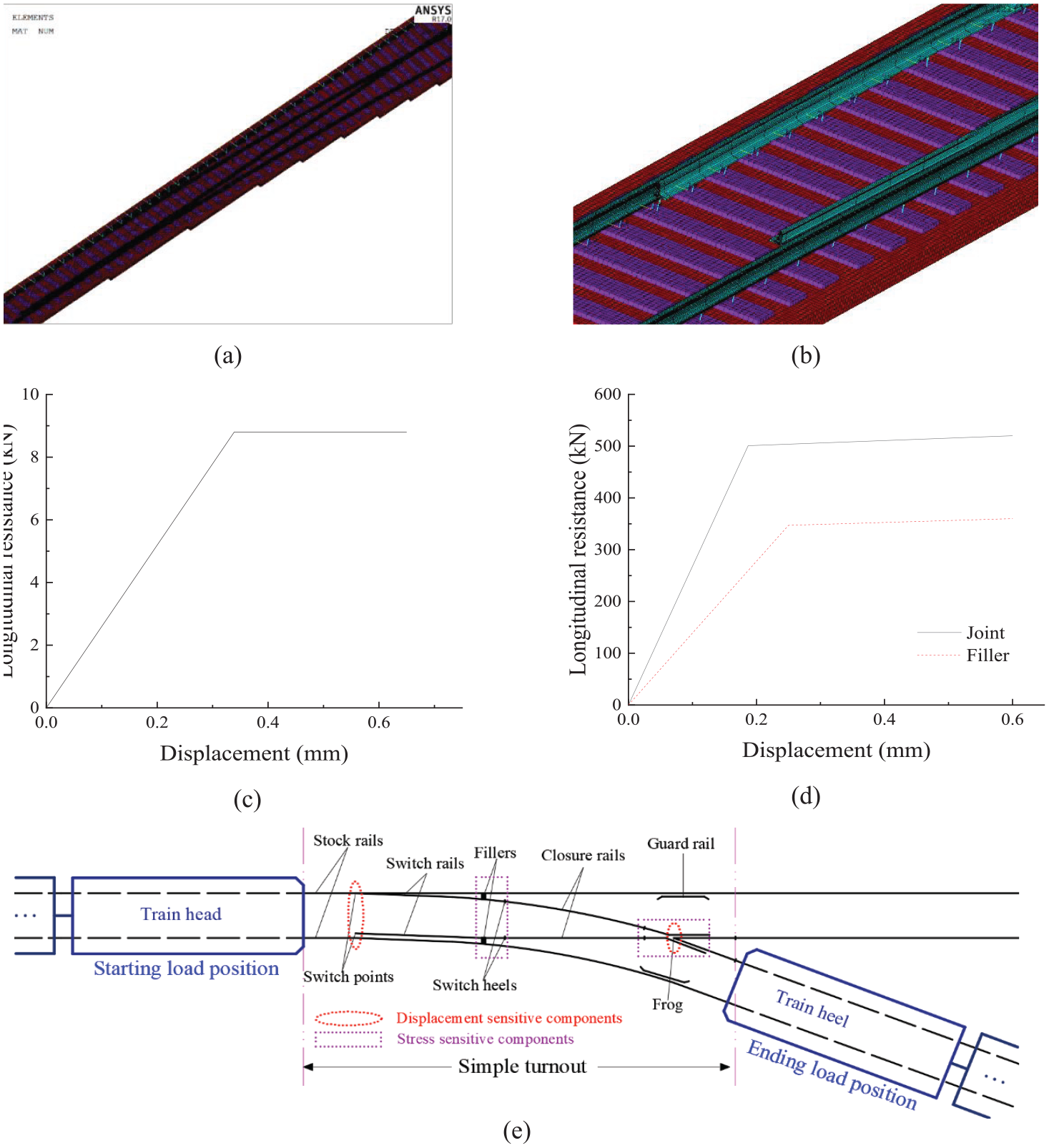
Schematic diagram of the analytical model: (a) turnout range, (b) switch rails, (c) longitudinal resistance of the fastener, (d) longitudinal resistance of joint and filler and (e) the components and the load position.
The most unfavourable loading condition
In this paper, calculations were based on a metro B-type train, composed of six carriages, with a total length and weight of 118.6 m and 336 t, respectively, a bogie pivot pitch of 12.6 m, rigid wheelbase of 2.3 m, four axles and an axle weight of 14 t. The train’s braking force is limited by the adhesion between the wheel and the rail; an adhesion coefficient of 0.25 was used for this study. 25 The longitudinal force acting on the top surface of the rail when the train is braking can be calculated as ‘braking force rate × vertical load of the train’.
In the literature, the train load is mostly simulated as a uniform load, which cannot effectively reflect the turnout’s stress and deformation changes during train operations. The No.9 simple turnout is commonly used in China’s metro system; its switch rail is about 11.2 m long. Since the bogie pivot pitch of a B-type train is 12.6 m and the rigid wheel base is 2.3 m, with a minimum distance of 14.9 m between four wheelsets of a single vehicle, and a minimum distance between three wheelsets of 12.6 m, there will be, at most, two wheelsets of a single vehicle acting on the switch rail at any given time. However, the two adjacent bogies of adjacent vehicles are 7 m apart, and these four wheelsets are at least 9.3 m apart. Therefore, in the process of train operations through the turnout area, there will be from one to four wheelsets acting on the switch rail at a given time. As the longitudinal force from the train on the track is generated due to wheel–rail interaction, the longitudinal force will be different when different numbers of wheelsets are on the switch rail. However, when using a uniform load to simulate the train’s operation, the longitudinal stress that the switch rail is subjected to is almost the same from the time the train head goes through the switch heel to the train heel going through the switch point. This cannot reflect the different stress from varying numbers of wheelsets acting on the switch rail at different times. Therefore, this paper adopts both uniform and concentrated loads to analyse and compare numerically the stresses on turnout structures during train operations.
The turnout crossing process is divided into 240 load positions: load position 1 is when the train head enters the turnout area; for each intermediate load position, the train will be advanced along the route by one fastener spacing; load position 240 is when the train heel leaves the turnout area. A schematic diagram of the loading positions, with the train passing through the turnout laterally, is shown in Figure 1(e).
Results and discussion
The most unfavourable loading position
Train loads were simulated by both uniform and concentrated loads. Through calculation, the displacement sensitive components are the movable components of the turnout, and the stress sensitive components are the elements at the longitudinal connections, as shown in Figure 1(e). Therefore, the longitudinal displacements of the two switch points, the frog and the fastener at the lateral switch heel, were used to show the turnout’s longitudinal displacement, while the longitudinal stress of the two stock rail elements at the fillers, the switch heels and the frog, were used to show the turnout’s longitudinal stress.
The relationships between loading position under the two loading modes and both longitudinal displacement and stress of turnout are compared in Figure 2, which shows that the change trends for the longitudinal displacement and stress for a given component are consistent for the two loading modes. However, when the concentrated load was used, the stress of the component has a strong relationship with the location of the wheelsets. Figure 2 illustrates the relationships between each component’s stress and displacement and the load position: ‘serrated’ under the concentrated load and ‘smooth’ under uniform load. When the concentrated load was used, the displacement and stress of direct-acting components of wheelsets vary greatly, while that of the other components vary slightly.

Relationships between turnout longitudinal displacement and force and loading position.
Statistics were calculated from the longitudinal displacement peaks and force of some turnout components under the two loading modes. Under a concentrated load, the peaks of each turnout component’s longitudinal force and displacement are greater than those under uniform load, but the increased amplitude is different. The train load increased the components’ peaks by a large proportion when acting on them directly. For example, the displacement and stress of the lateral switch rail and the frog increase by more than 30%, while the straight switch rail, one of the components that the train load acted on indirectly, increased only 4%. This shows that the structural components’ actual stress may be greater than the results calculated using uniform load, suggesting that the results using uniform load are unsafe, and the results of the concentrated load calculation should be used to check strength and stability.
Nonetheless, the results calculated under the uniform load are useful as a guide. Because the train length is greater than the turnout’s total length, the peak longitudinal stress and displacement of most structural components occur when the train covers the entire turnout section.
The most unfavourable load position is different for different structural components. Through comprehensive analysis of the calculation results of the two loading modes, the 108th load position represents the situation where the two bogies adjacent to the vehicles in the third and fourth sections of the train act on the switch rail, the train covers the entire turnout area, and four wheelsets act on the switch rail at the same time. At that point, the switch rail’s longitudinal displacement and stress reach their maximum values, and the other structural components’ displacement and stress are at or close to their respective maximum values. This is, therefore, the most unfavourable load position.
Influence of gradient on longitudinal displacement and stress of the turnout under braking force
Trains often apply braking on steep slopes, and the braking load should be superimposed on the train load’s ramp component. Consequently, the gradient will affect the turnout’s longitudinal stress. The braking force is the product of the braking coefficient μ and the vertical train load Q: Fb = Q × μ. Due to the small ramp angle α, the train’s ramp component F2 = Q × sinα ≈ Q × tanα = Q × i. Therefore, the longitudinal force on the track on the ramp is F = Fb ± F2 = Q × (μ ± i). Obviously, when the braking force is directed from the top to the bottom of the slope, its direction is consistent with the component force of the train load ramp, and superimposing the two is most unfavourable to the turnout’s longitudinal force and deformation.
When the train laterally passes the turnout, the calculation of dynamic train load needs to consider the influence of the train speed and unbalanced train load. The driving speed V is 35 km/h, and the radius R = 200.718 m.
Speed factor: Eccentric load factor:
Wheel dynamic load value:

Therefore, the value of the longitudinal braking force when the train is passing through the turnout at different gradients can be obtained by bringing different gradient values into the above formula (1).
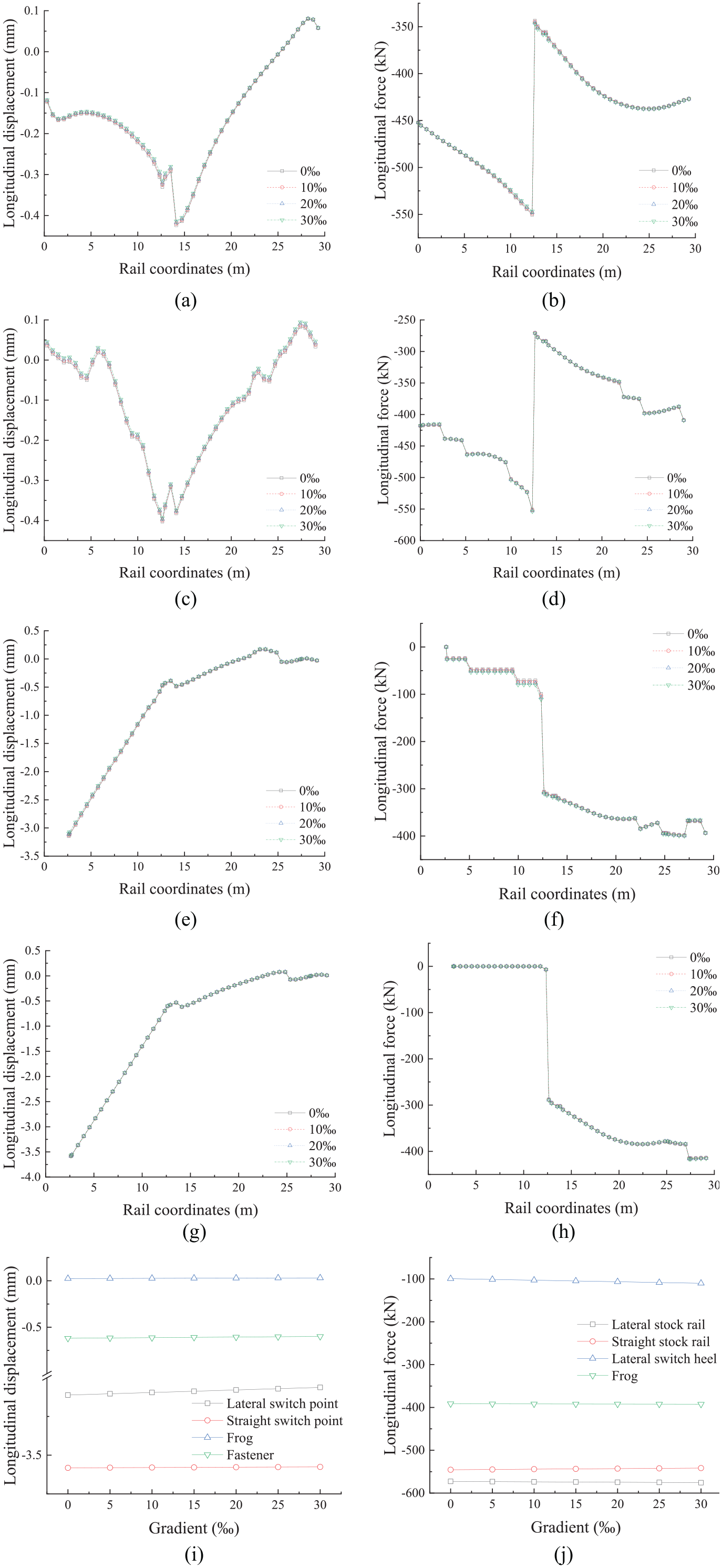
We analysed the relationship between longitudinal displacement, the force of turnout structural components and the gradient, for gradients of 0‰, 5‰, 10‰, 15‰, 20‰, 25‰ and 30‰, when the train passes laterally through the turnout section. When drawing the displacement and force distribution diagrams of the rails along the turnout line, since more slopes were calculated, only the turnout structures with gradients of 0‰, 10‰, 20‰ and 30‰ were selected. The longitudinal displacement and force of the rail are shown in Figure 3(a) to (h). Finally, statistics were made on the maximum longitudinal displacement and the maximum longitudinal force of each turnout rail at the slopes of 0‰, 5‰, 10‰, 15‰, 20‰, 25‰ and 30‰, the relationship between displacement and slope is shown in Figure 3(i), and the relationship between force and slope in Figure 3(j). The results are shown in Figure 3.

The relationship between longitudinal displacement, force and gradient: (a) longitudinal displacement of straight, (b) longitudinal force of straight stock rail, (c) longitudinal force of straight stock rail, (d) longitudinal force of lateral stock rail, (e) longitudinal displacement of lateral switch rail, (f) longitudinal force of lateral switch rail, (g) longitudinal displacement of straight switch rail, (h) longitudinal force of straight switch rail, (i) longitudinal displacement peak and (j) longitudinal force peak.
The results in Figure 3 show that, when the train brakes on a large slope while crossing the turnout laterally, the turnout’s overall longitudinal displacement direction is the same as the travelling direction, and the displacement increases with the gradient’s increase. The lateral switch rail’s longitudinal displacement is larger than that of the straight switch rail due to the action of the train, and the relative displacement between the two switch rails increases with the gradient’s increase. The displacements of the two switch points relative to the stock rails are in opposite directions and increase with the gradient’s increase. Directly acted on by the train load, the relative displacement between the lateral switch rail and the straight stock rail is positive. Although the straight switch rail’s longitudinal displacement is also positive due to the positive displacement of other structures, its displacement is smaller than that of the lateral stock rail, so the relative displacement between them is negative. In terms of structural stress, the longitudinal forces on the two switch rails are clearly different: the longitudinal force on the lateral switch heel is the larger, due to the direct action of the train its connection to the straight stock rail through the filler. The stress on the straight stock rail element at the filler is also high.
With the gradient’s increase, the longitudinal displacement and stress on each structural component of the turnout increase linearly. When the gradient increases from 0‰ to 30‰, the maximum longitudinal displacement and stress of each structural component of the turnout increase by more than 10%. This shows that gradient increase is unfavourable to the turnout structure’s longitudinal displacement and stress.
Influence of temperature change on longitudinal displacement andstress of the turnout
In addition to the train load, the track structure in a subway tunnel is subjected to a temperature load, which also affects the turnout structure’s longitudinal displacement and stress. According to the relevant standards of tunnel ventilation systems, the ground minimum temperature in winter is 0°C and the maximum temperature in summer is not more than 45°C. The rail fastening-down temperature is determined to be 25°C ± 5°C. Therefore, although the tunnel temperature changes only slightly, on the basis of the fastening-down temperature, the rail temperature varies within ±25°C. 26
The longitudinal displacement and force of each structural component of the turnout were analysed through a temperature variation range of ±25°C. The results are shown in Figure 4.

The relationship between longitudinal displacement, force and temperature change: (a) temperature force on turnout, (b) longitudinal displacement of straight stock rail, (c) longitudinal force of straight stock rail, (d) longitudinal displacement of lateral stock rail, (e) longitudinal force of lateral stock rail, (f) longitudinal displacement of lateral switch rail, (g) longitudinal force of lateral switch rail, (h) longitudinal displacement of straight switch rail, (i) longitudinal force of straight switch rail, (j) longitudinal displacement peak and (k) longitudinal force peak.
Under the same temperature change amplitude, the longitudinal displacement and force of each turnout rail under positive temperature change is symmetrical with the negative temperature change, that is, the directions of the displacement and force in the two temperature environments are opposite but the values are almost the same. Therefore, only the situation of negative temperature change was considered here.
Figure 4(a) shows the temperature change’s influence on the stress of turnout rails. The stock rails are called the outer rails, and the rest are all inner rails. Due to the lack of longitudinal restraint, the turnout’s inner rails are similar to the breathing zone in CWR, and the temperature force on the inner rails will be transmitted to the outer rails through the fillers. When the temperature change is >0, the rail expands, so the turnout’s right side will bear the temperature force of the non-breathing zone transmitted by the four rails, while the left side will only bear it from two rails. Thus, the temperature forces borne by both ends of the turnout are unbalanced, which will inevitably cause an overall displacement of the turnout rails to the left. Under these conditions, the temperature forces of the front section of the switch rails are small, and the other turnout rails will bear compressive stress. Conversely, when the temperature change is less than 0, the turnout rails will move to the right under tensile stress.
Figure 4(b) to (i) illustrate the turnout rails’ longitudinal displacement under varying temperature changes. The results show that, under the temperature load, the switch rail’s longitudinal displacement is large, but the switch point is the largest. There is almost no relative displacement between the two switch rails, and the relative longitudinal displacements between the switch rails and the stock rails are consistent. In terms of the turnout’s longitudinal stress because of the lack of longitudinal restraint, the switch rails are subjected to less temperature force, but the rail elements between the filler and the joint at the switch heel bear obvious temperature force. The stock rails are subjected to greater temperature stress. The components with the greatest temperature force are the rail elements near the fillers because the temperature forces of the inner rails are also transmitted to the stock rails through the fillers, and the part of the frog that bears the greatest longitudinal force is the frog heel end.
Figure 4(j) and (k), respectively, show the turnout components’ longitudinal displacement and force peaks under varying temperature changes: displacement and force increase with increased temperature changes. Under the temperature load, each structural component’s longitudinal displacement and force peaks are approximately equal, regardless of whether the turnout is in a straight or lateral crossing state, and increase linearly with increased temperatures.
In addition, when the temperature drops by −25°C and the turnout slope is 0‰, 10‰, 20‰, 30‰, while there is no train braking effect, the maximum longitudinal displacement and force of turnout rails are shown in Table 2.
Maximum longitudinal displacement and force of each rail of the turnout.

The rail displacement is positive if it is consistent with the driving direction. The axial force of the rail is positive in tension and negative in compression.
It can be seen from Table 2 that under the action of negative temperature load alone, the slope gradient has negligible influence on the turnout structure’s stress and displacement.
Combined working condition
From the above analysis, it is clear that the increase of slope under the action of train braking force and temperature change produce negative effects on the turnout structure’s longitudinal displacement and stress. When the two conditions are combined, the turnout structure’s longitudinal displacement and stress will be worse than when the two conditions act separately. The analysis shows that, when the temperature change is negative, the turnout structure’s displacement direction is consistent with that of the train braking, and when the temperature change is positive, the stress direction is consistent with that of the train braking. Therefore, the train braking’s influence on the turnout structure’s longitudinal stress and displacement under different gradients with temperature changes of ±25°C was studied, and the results are presented in Figure 5.

The relationship between longitudinal displacement, force and the gradient with a temperature change of −25°C: (a) longitudinal displacement of straight stock rail, (b) longitudinal force of straight stock rail, (c) longitudinal displacement of lateral stock rail, (d) longitudinal force of lateral stock rail, (e) longitudinal displacement of lateral switch rail, (f) longitudinal force of lateral switch rail, (g) longitudinal displacement of straight switch rail, (h) longitudinal force of straight switch rail, (i) longitudinal displacement peak (−25°C) and (j) longitudinal force peak (−25°C).
The results in Figures 5 and 6 show that, when the train is braked on a large ramp and passes through the turnout laterally under temperature changes of ±25°C, the turnout structure’s displacement and stress are similar to those when the temperature load and train braking load act separately.
The relationship between longitudinal displacement, force and the gradient with a temperature change of +25°C: (a) longitudinal displacement of straight stock rail, (b) longitudinal force of straight stock rail, (c) longitudinal displacement of lateral stock rail, (d) longitudinal force of lateral stock rail, (e) longitudinal displacement of lateral switch rail, (f) longitudinal force of lateral switch rail, (g) longitudinal displacement of straight switch rail, (h) longitudinal force of straight switch rail, (i) longitudinal displacement peak (+25°C) and (j) longitudinal force peak (+25°C).
The turnout’s longitudinal displacement with a temperature change of −25°C is larger than that with a temperature change of +25°C. When the temperature change is −25°C, the turnout as a whole has the same longitudinal displacement direction as the direction of train travel, and the displacement increases with an increase in gradient, which is a greater effect than the working conditions when the temperature load and the train braking load act separately. The lateral switch rail’s longitudinal displacement is larger than that of the straight switch rail. Due to the superimposition of temperature loads, the displacement directions of the two switch points, relative to the stock rails, are the same and the longitudinal displacement of the lateral switch rail, relative to the stock rail, increases with the increased gradient, while that of the straight switch rail decreases. This is the same as the superimposition behaviour when the two loads act separately. Since the temperature load does not cause a relative displacement between the two switch rails, their displacement is almost the same as that of the train braking load under the combined conditions and increases with an increased gradient.
The two stock rails’ longitudinal stress is relatively large, and the rail elements close to the filler bear the greatest stress. When the temperature change is +25°C, the longitudinal forces on the two switch rails are clearly different, but both increase when the gradient increases. Due to the direct effect of the train load, the longitudinal force on the lateral switch heel is relatively large. Also, with the gradient increase, the longitudinal force of the stock rails and the frog increase.
The displacement and stress of structural components of the turnout show that, under the combined action of temperature change and train braking load, a gradient increase is unfavourable to the turnout structure’s longitudinal deformation and stress.
Figure 7 shows the longitudinal displacement and force diagram of the three fasteners at the lateral switch heel. It is worth noting that, when the train is braking on a large ramp and passing through the turnout laterally under a temperature change load of −25°C, the distance of the first, second and third fastener nodes from the switch point increases sequentially, and the longitudinal displacement of the three fastener nodes increases linearly with a gradient increase. However, the longitudinal force provided by the fasteners remains the same, indicating that the fastener has reached a slip state. At the same time, the lateral switch rail heel’s filler and joint are still within the elastic stage and have not slipped.
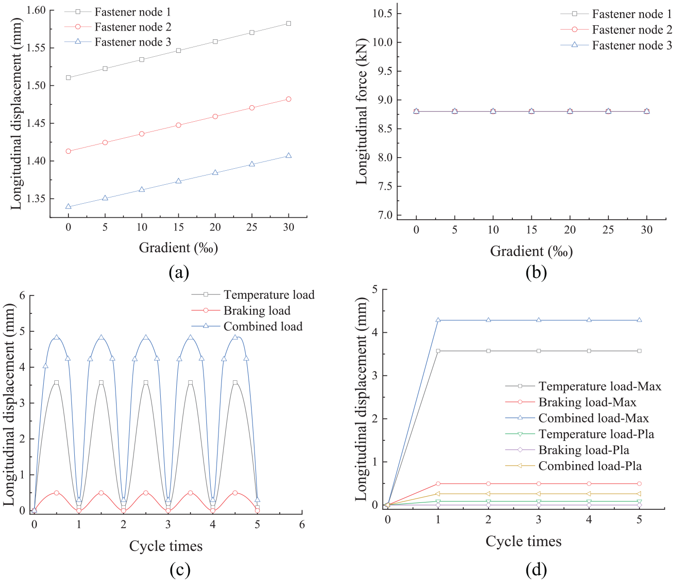
The relationship between the longitudinal displacement and force peaks of three fasteners at the heel of the lateral switch rail and the gradient: (a) longitudinal displacement peak, (b) longitudinal force peak, (c) relationship between the longitudinal displacement of switch point and cycle times under different working conditions, and (d) relationship between the maximum/plastic longitudinal displacement of switch point and cycle times under different working conditions.
In the entire turnout area, three fasteners have reached a slip state, while the other fasteners are in an elastic state. Figure 7(c) and (d) illustrate the relationship between the lateral switch point’s longitudinal displacement and load cycle times under different working conditions. Under the train braking load cycle, all fasteners are within the elastic range, and there will be no plastic displacement at the switch point. Under the temperature and combined cycle load, the fasteners at the switch heel will slip, and there will be some plastic displacement on the switch point after unloading. With the reciprocating combined loads and the fasteners’ current elastic-plastic hysteretic characteristics, the maximum and plastic longitudinal displacement of the switch point will not accumulate over time, but will converge to 4.815 and 0.272 mm, respectively, after the first load cycle and attain a new balance. In the following cycles, the fastener’s maximum longitudinal displacement and force at the switch heel will reach a critical elastic state of the new balance and will not continue to slip. Confirmation of this behaviour is described in detail in section 3.6.
Strength and stability calculation of turnout rail under combined working conditions
Turnout rails should be strong enough to ensure that they will not fail under the combined action of dynamic bending stress, temperature stress, train start-up and braking stress, and any additional stresses. The sum of various stresses borne by the rail cannot exceed the specified allowable value [σ]:

where σd is the maximum dynamic bending tensile stress of rail (MPa); σt is the temperature stress (MPa); σf is the maximum additional stress the rail bears (MPa); and σz is the traction (braking) stress of the rail (MPa). [σ] is the allowable stress of the rail (MPa) and is equal to the yield strength σs of the rail divided by the safety factor K, [σ] = σs/K. For U75V rail, [σ] = 363 MPa. 21
Axial stress is used to replace the combined effect of temperature stress, train start-up and braking stress, and other stresses on the rail. Across a temperature range of ±25°C, the rail stress when the train is braking through the turnout on a 30‰ slope was obtained. The turnout components’ rail strength and longitudinal displacement are listed in Table 3.
Strength and stability of components.
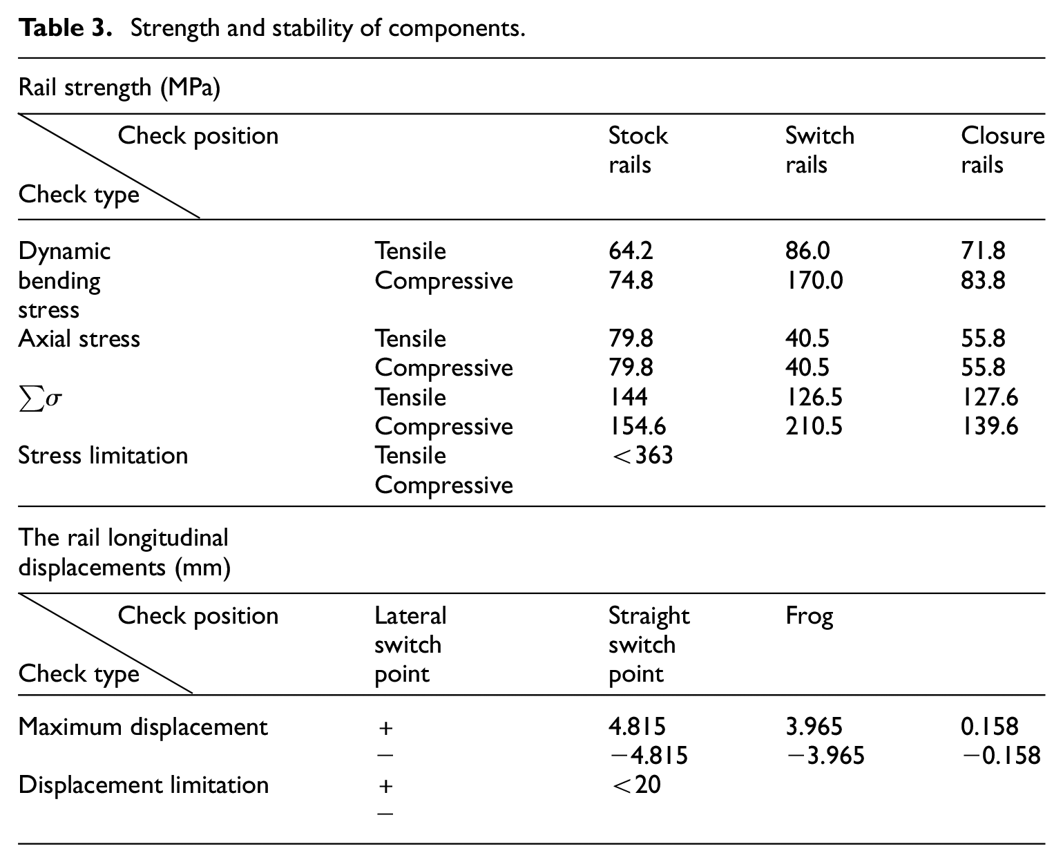
The maximum relative longitudinal displacement between the two switch rails is 0.79 mm, and that between the switch rail and the stock rail is 4.14 mm. The results show that the stress of each rail in the turnout structure is less than the allowable rail stress, and each rail’s longitudinal displacement is also less than the maximum displacement allowed by the specification, so the strength and stability meet the specification requirements.25,27 This confirms that, under the combined action of temperature load and train braking load, even if the turnout is on a 30‰ ramp, it will not experience structural damage under one cycle load.
Plastic cumulative displacement of the switch rail
The sliding fastener node, mentioned in section 3.4, has its own fasteners providing longitudinal constraint. Other longitudinal resistance components (fasteners, rail joints and fillers in the elastic stage) also constrain this node longitudinally. Because the fastener has an elastic-plastic hysteresis effect, a slipped fastener can be simulated by an integral elastic-plastic spring, where the longitudinal rigidity in the elastic stage is k1, and the slip resistance is Fs; However, other longitudinal resistance components are in an elastic stage because they do not slip, and they can be simulated by a second linear spring with a stiffness of k2. Both springs provide longitudinal restraint for this node and are in a parallel relationship. A schematic diagram is shown in Figure 8.

Schematic diagram of longitudinal force-displacement at joints of sliding fasteners: (a) longitudinal constraint relation and (b) fastener resistance-displacement curve.
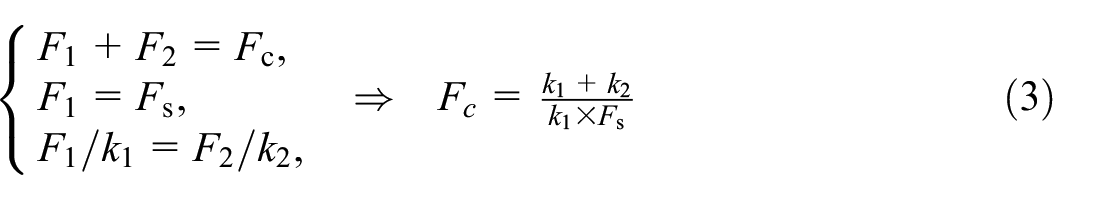
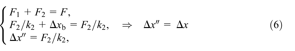
As shown in Figure 8(a), the rail element at this node is simplified as a rigid body, and the two springs are connected to it to provide longitudinal restraint. Due to the elastic-plastic hysteretic characteristics of the fastener, there is a critical force Fc such that, when a longitudinal force F ≤ Fc is applied to the node, the node fastener will not slip under the action of the F, and the node will return to its initial position after unloading. However, when F > Fc, the node fastener slips and the node cannot return to its initial position after unloading. An equilibrium equation (3) enables the critical longitudinal force Fc of slip for the node, corresponding to the point A in Figure 8(b), to be calculated. When F > Fc, as shown in the second part of Figure 8(a), the equilibrium equation (4) gives the maximum longitudinal displacement


Therefore, with the current constitutive relation of longitudinal resistance components, even if individual fasteners reach the slip state, they will reach stability after the first cycle. In fact, the measured resistance displacement curve of the fastener does not display an ideal bilinear model. At the beginning of loading, the resistance of the fastener increases linearly with the displacement, and the stiffness of the fastener remains unchanged, this is the stage of elastic deformation. When the rail longitudinal displacement reaches D3, the rail displacement begins to increase rapidly, the fastener resistance still increases slightly, and the fastener longitudinal stiffness gradually decreases, which is the yield stage; Furthermore, with the continuous increase in rail displacement and the unchanged fastener resistance, the fastener rail slip stage was reached, as shown in Figure 9. When the train is running, the longitudinal force transferred to the fastener does not reach the value of the longitudinal resistance of the fastener. However, many studies show that, due to subways’ high traffic density, under many cyclic loads, especially the high-frequency vibration caused by wheel–rail interaction, the toe load of fastener clips and the bolt torque of joints and fillers will decrease; thus, the line’s longitudinal resilience will decrease. Consequently, the longitudinal force acting on the fastener may reach the elastic-plastic limit of the fastener, and the fastener is in the yield stage. Thus, the rail will produce irrecoverable residual displacement after loading and unloading. With the increase of train operation times, the rail residual displacement gradually accumulates, and when it accumulates to a certain extent, it will have adverse effects on the stress and deformation of the turnout structure. In such cases, the equilibrium state with the traditional bilinear model of fastener longitudinal resistance cannot be maintained, and the nodes will continue to slip forward. Therefore, the traditional bilinear model cannot reflect the yield stage of the fastener, else it will lead to inaccuracy in the calculation value of the cumulative displacement, and provide wrong guidance for the design and construction of the turnout.
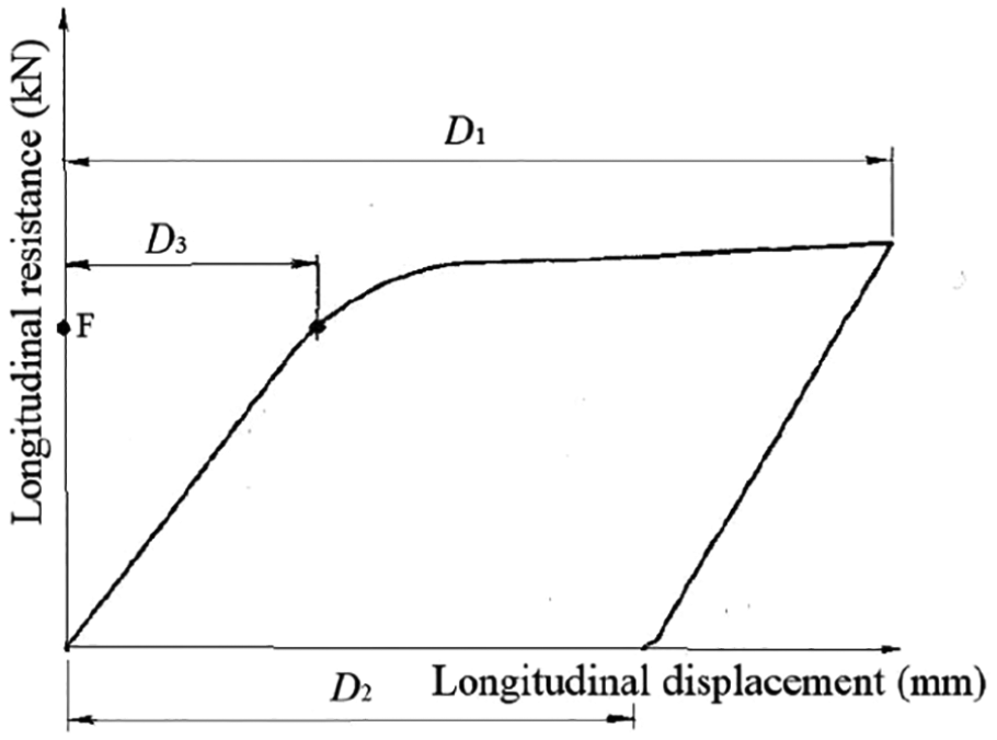
Fastener resistance-displacement curve.
From the figure above, D1 is the maximum longitudinal displacement of the rail during loading, D2 is the residual longitudinal displacement of the rail after unloading and D3 is the elastic longitudinal displacement before the rail slips.
This study also tested the fasteners’ longitudinal resistance characteristics under reciprocating load, using the experimental setup shown in Figure 10(a). The sleeper was fixed rigidly to the base, and a 0.6 m length of rail was attached to the sleeper, using elastic strip type III fasteners. Two symmetrical force application components were arranged at the ends of the rail, alternately applying bidirectional longitudinal tension, to create a bidirectional reciprocating loading on the rail and the tension was recorded continually. Underneath the rail, there were two displacement sensors to measure the longitudinal displacement between the rail and the sleeper. Recording the longitudinal force and displacement from applying the force produces a longitudinal displacement curve of the rail under different cycle numbers, which describes the fastener’s longitudinal resistance characteristics. In order to reflect the longitudinal elastic-plastic characteristics of fasteners in the loading system properly, the rail’s left and right maximum longitudinal displacement was set to 4 mm at a loading speed of 10 kN/min in the following manner. 22 A pulling force was initially applied longitudinally to the left. When a displacement of 4 mm was reached, the pulling force was replaced by one at the right end, to pull the rail to the right; When the rail displacement reached 4 mm to the right relative to the initial position, the initial force application component at the left end was restarted, pulling the rail back to the initial position. This constituted a complete load cycle.

Longitudinal resistance-displacement test of fasteners under reciprocating loads and the relationship between the longitudinal displacement of the lateral switch point and the proportion of slip resistance reduction of the fastener: (a) experimental setup, (b) fastener resistance-displacement curve, (c) maximum longitudinal displacement and (d) residual longitudinal displacement.
The longitudinal resistance and displacement data of the 5–15, 4995–5005 and 9995–10,005th cycles were averaged to represent the longitudinal force-displacement curves of the 10, 5000 and 10,000th cycles, respectively, and are plotted graphically in Figure 10(b).
As Figure 10 shows, the longitudinal resistance-displacement curves of the fastener at the 10, 5000 and 10,000th cycles are not exactly coincident: the fastener slip resistance decreases with increasing cycles. At the 10, 5000 and 10,000th cycles, the fastener slip resistances are 9.756, 9.270 and 8.738 kN respectively, that is, at the 5000 and 10,000th cycles, the slip resistances are 4.98% and 10.43% lower, respectively, than the initial resistance.
Combined with the previous analysis, the decrease in slip resistance of the fastener confirms that the equilibrium state of the switch rail cannot be maintained: it will slip under the same longitudinal force. Therefore, a life-and-death element method was used to simulate the decline of the fastener slip resistance.28–30 Assuming that the fastener’s slip resistance decreases linearly with the load cycles, and considering the cases when the fastener slip resistance fell by 2.5%, 5%, 7.5%, and 10%, respectively, the relationships between the maximum and residual longitudinal displacement of the switch point and the gradient under the combined action of temperature change and train braking load were studied. The calculation results are shown in Figure 10(c) and (d).
As can be seen from Figure 10(c) and (d), when the turnout was on 0‰ and 30‰ slopes, under the simultaneous action of the temperature and train braking loads, the maximum longitudinal displacements of the lateral switch point were 4.73 and 4.82 mm, respectively. When the temperature and train braking loads were removed, residual longitudinal displacements of 0.25 and 0.27 mm, respectively, were obtained at the switch point. However, the fastener’s slip resistance decreases with the increased cycle times. When the fastener’s slip resistance decreases by 5%, the switch point’s maximum longitudinal displacements are 4.80 and 4.89 mm, respectively, with corresponding residual displacements of 0.28 and 0.30 mm. When the fastener’s slip resistance is reduced by 10%, the longitudinal maximum displacements of the switch point are 4.88 and 5.01 mm, respectively, with residual displacements of 0.31 and 0.34 mm, respectively.
When the gradient is small, with the decrease of fastener slip resistance, the switch point’s maximum longitudinal displacement increases linearly. Compared with the initial state, the switch point’s longitudinal displacement increases by about 3.1% when the fastener slip resistance decreases by 10%. However, when the gradient is 30‰, the switch point’s maximum longitudinal displacement displays a nonlinear and accelerating trend. When the slip resistance of the fastener is reduced by 10%, the longitudinal displacement increases by about 4.0%. At the same time, if the fastener’s slip resistance decreases from 0% to 10%, and if the gradient increases from 0% to 30%, the maximum longitudinal displacement of the switch point increases continuously, from 1.7% to 2.7%. This indicates that a gradient increase will intensify the impact of the fastener longitudinal stiffness decrease on the turnout structure.
Similarly, the residual longitudinal displacement of the switch point shows an increasing linear trend as the fastener slip resistance decreases. When the fastener’s slip resistance decreases by 10%, the residual longitudinal displacement increases by more than 25%. However, with a gradient of 30%, the switch point’s residual longitudinal displacement is about 9% higher than that with a gradient of 0%. It can be predicted, therefore, that, with a further decrease of fastener longitudinal stiffness, the switch point’s residual longitudinal displacement will increase more rapidly.
Further, because trains do not need to be braked as frequently when running on flat terrain as opposed to a steep slope, the actual difference in the switch rails’ residual longitudinal displacement may be even greater. Therefore, under the same conditions, a gradient increase will cause the turnout’s residual longitudinal displacement to accumulate more rapidly, requiring more frequent maintenance work.
The above calculations also show that it is necessary to observe the longitudinal displacement of turnouts when laying turnouts on steep slopes. Increasing the longitudinal resistance of the fasteners, rail joints and spacers is of great practical significance for controlling turnout longitudinal displacement on steep slopes.
Conclusions
To study the advisability of subway turnouts on steep slopes, a finite element model of a metro No. 9 turnout was established, and the slope’s influence on the turnout structure’s longitudinal stress and displacement under train braking and temperature change was studied. The research conclusions are as follows:
There is a clear difference between calculations using uniform load and concentrated load to simulate the train. Using a concentrated load was more realistic and effective in simulating the structure’s stress and displacement when the train passes through the turnout. The turnout structure’s most unfavourable overall stress and displacement occurs when the two adjacent bogies of the third and fourth train carriages are on the switch rail.
A large gradient is unfavourable to the turnout structure’s longitudinal stress and displacement. Under a train braking force, each turnout component’s longitudinal displacement and stress increase linearly with a gradient increase. As the gradient increases from 0‰ to 30‰, the longitudinal stress and displacement increase by more than 10%.
The temperature change is unfavourable to the turnout structure’s longitudinal stress and displacement. However, under temperature load alone, the slope gradient has negligible influence on the turnout structure’s stress and displacement. When temperature load is combined with train braking load, the turnout’s displacement and stress increase linearly with the gradient increase and are greater than the working conditions when the two loads act separately.
Even on a 30‰ slope, the turnout components’ rail strength and longitudinal displacements are still within specification limits.
The switch point’s maximum and residual longitudinal displacements converge to those in the first load cycle. However, as the load cycles increase, the fastener slip resistance decreases gradually, and a gradient increase will intensify the impact of the decrease of fastener longitudinal stiffness on turnout structure.
In practical engineering terms, the turnouts’ longitudinal displacement accumulation should be carefully monitored. Increasing the longitudinal stiffness of fasteners, joints and fillers is of great practical significance for the control of the turnouts’ longitudinal displacement on steep slopes.
Footnotes
Declaration of conflicting interests
The author(s) declared no potential conflicts of interest with respect to the research, authorship, and/or publication of this article.
Funding
The author(s) disclosed receipt of the following financial support for the research, authorship, and/or publication of this article: The work described here has been supported by the High-speed Railway Joint Fund of National Natural Science Foundation of China (Grant U1734208), Hunan Provincial Natural Science Foundation of China (Grant 2019JJ40384), and the Fundamental Research Funds for the Central Universities of Central South University (Grant 2019zzts873).