
Abstract
The train sometimes needs to brake frequently on the turnout, although the braking force does not exceed the limit resistance of fastener, cumulative displacement of rail occurs because of the long-term effect of the train brakes, thus, the relationship between the cumulative displacement of rail and the number of train braking actions should be explored. Aiming at the spring bar type III fastener, a 1:1 physical indoor simulation test was carried out, and an electromagnetic relay device was used to simulate the train load, force, and displacement sensors for data collection. Then a single load no more than the maximum resistance of fastener was applied to the rail end to explore the relationship between the number of loads and the rail cumulative deformation. The rail longitudinal cumulative displacement changes linearly in positive correlation with the number of load actions, and increases faster when the number of load actions is small. As the number of repeated loads increases, the above-mentioned relationship approximately and credibly obeys the power function distribution. Repeatedly applying load no more than the maximum longitudinal resistance of fastener to the rail, the existence of the rail cumulative displacement caused by frequent train braking can be demonstrated, and the relationship curve between the rail displacement and the number of loads can be obtained. Applying the fitting formula, the rail displacement after a specific number of loading times can be attained, and then referring to specific codes, we can determine whether it will exceed the safety limit.
Keywords
Introduction
During train operations, the area where the train enters the railway station is frequently subjected to the action of train braking.1,2 Under the cumulative effect of the braking force of the train, an irreversible cumulative displacement between the fastener and the rail occurs. The existence of the cumulative displacement of the rail does not only causes internal stress that cannot be released and restored, but also reduces the safety of the track structure. At the same time, when the cumulative displacement reaches a high level, a huge friction between the rail and the under-rail pad is generated which will cause fastener pad slipping out of the slab3–6 (Figure 1), which has a serious impact on the safety of train operations.

The slip phenomenon of fastener pad under cyclic load.
To simplify calculations in the traditional railway design, the influence of rail and the cumulative longitudinal displacement of rail is often ignored.7–12 The Finite Element Method was applied to develop a three-dimensional (3D) model of a fastening system and a 3D railway track model to explore the complicated characteristics of fasteners and rails under single load. 13 The test and numerical calculation were used to evaluate and predict the mechanical behavior and the fatigue life of fastening systems.14,15 In addition, longitudinal resistance tests of fastening systems were conducted to determine changes in track resistance that occur at the instant of application or release of a vertical load, 16 to evaluate the fasteners’ performances in attenuating impact loads, 17 and to test the characteristics of constant-resistance and small-resistance fasteners under varying torques and vertical loading, 18 etc. However, there is no study experimentally or numerically focused on the cumulative rail-fastener displacement.
Furthermore, in the traditional fastener longitudinal resistance bilinear constitutive, it’s believed that when the load does not exceed fastener sliding resistance, the rail will return to the equilibrium position after unloading, and the rail displacement and the loading path of the load curve are consistent with the slope of the unloading path.9,19–21 However, this is not the case after repeated loading and unloading, fasteners will gradually fail to completely restrain the rail from displacement, which will result in the cumulative displacement of rail.
Therefore, it is necessary to conduct an experimental study on the cumulative effect of rail displacement to explore the relationship between the longitudinal displacement of rail and the number of loading cycles under different unidirectional cyclic loads, and to predict the cumulative displacement of rail after multiple loading, which is helpful for the railway line designer and maintenance workers, and at the same time provides experimental basis for improvement of fastener constitutive relationship.
Materials and methods
Materials
The materials/equipment used for this study are spring bar type III split fasteners, displacement, and force sensors and a data acquisition system.
Spring bar type III split fasteners
The frequent braking action of trains often occurs near the turnout close to the station, and the turnout center is a weak position in the turnout. Due to the limitation of the space range in the turnout, spring bar type III fasteners are often used,22,23 so we chose this type of fastener for experimental research (Figure 2).

Physical picture of spring bar type III fastener.
➀ It has no shoulders and no bolt fasteners, suitable for laying 60 kg/m rail on standard gauge lines;
➁ the gauge is adjusted by changing the insulating gauge block, the adjustment limit is −8 to +4 mm;
➂ It is suitable for track with 60 kg/m rail without shoulder and with concrete sleeper on straight line or curve with radius R ≥ 350 m on standard gauge railway rail.
➀ The initial buckle pressure of a single spring bar is not less than 11.0 kN; the projectile range is 13 mm;
➁ The ability to resist lateral static force is 100 kN, fatigue load is 70 kN, load cycle limit is twomillion cycles; gauge expansion value is less than 2 mm;
➀ If fastener components are not damaged; the vertical static stiffness of each fastener node is 60–80 kN/mm;
➁ The pull-out resistance of the embedded iron seat is not less than 60 kN; the height adjustment amount of this fastener is 0.
Displacement and force sensors
Linear variable displacement transformer (LVDT) displacement sensor
The displacement sensor used is LVDT (Figure 3), which is used to measure the relative displacement between the rail and the sleeper. It has characteristics as follows: strong anti-interference ability, high output sensitivity, good resolution, linearity, repeatability and stability, small size, convenient installation (using a magnetic stand), and convenient operation. The displacement sensor used is made by Chaoyuan Instrument Factory in China. Its serial number is ZNYY125/YWC-10, measurement range −5 to +5 mm and sensitivity 0.340 mV/mm.

LVDT.
Spoke type load cell
The load cell is a conversion device that measures the weight signal or pressure signal through a metal resistance strain gauge pasted on a metal weighing beam, and converts the signal into a power signal (Figure 4). The force sensor used is the spoke type load cell NOS-F301, which is used to measure the tensile force exerted by the loading equipment (jack) on the rail. It is manufactured by Changsha Nosysis Instrument Co., Ltd. The range of the sensor used in the test is 30 kN.

Spoke type load cell.
Data acquisition system
The data acquisition system is DH3822 portable dynamic signal test and analysis system(Figure 5), manufactured in China by Donghua Testing Technology Co., Ltd. DH3822 works with various bridge sensors to accurately test physical quantities such as force, pressure, displacement, velocity, acceleration, etc., and can achieve multi-channel parallel high-speed and long-term continuous sampling. During the measurement, the computer communicates with the instrument through the Ethernet interface and 4G network (WiFi is optional) to set the parameters (range, sensor sensitivity, etc.), clear, sample, and stop the collector, and transmit the sampled data in real time. The sampling frequency used in the test is 50 HZ.

DH3822 portable dynamic signal test and analysis system.
Train braking load simulation method
The longitudinal resistance of fasteners and cumulative displacement of rail were tested according to the specification “Test methods for fastening systems of high-speed railway-Part 1: Determination of longitudinal rail restraint” (TB/T 3396.1-2015). 24
During the fastener longitudinal resistance test, the rail was fixed on the sleeper with fasteners according to the standard assembly state, and the load was applied to the center line of rail bottom. A displacement sensor was arranged at the center of rail section to measure the longitudinal displacement of the rail (the displacement sensor was fixed on the sleeper), and the displacement sensor is set to 0. The test set-up schematic diagram is shown in Figure 6, where 1 is the rail, 2 is the fastener, 3 is the displacement sensor, 4 is the sleeper, and 5 is the base fixing device. During the test loading, a tensile force was applied to the rail at a constant loading rate of 10 kN/min, and the load and the longitudinal displacement of rail relative to fastener were measured at the same time. When the rail slips, the set-up is quickly unloaded to 0 load and the rail displacement is continuously measured for 2 m.
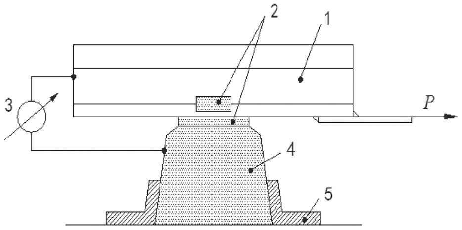
Schematic diagram of test device.
When testing the rail cumulative displacement, the jack is connected to the relay device through the signal transmission line and the loading time of the relay device is adjusted through the control on the relay device. The loading is performed every 38 s, and the duration of each loading is 2 s, which is to simulate the train passing through once every 38 s, and each duration is 2 s. After a simulated force, the jack is used to unload the force and waited for 38 s before the next loading period of 2 s. In this way, the cycle of loading and unloading was repeated throughout the experiment.
Cumulative longitudinal displacement of rail
Analysis of rail longitudinal displacement-load relationship
In this study, the spring-bar type III split fastener was considered. Fastener was not disassembled and adjusted in any way during the test. The aforementioned (Section 2.1) loading and unloading process was repeated three times, and after each unloading, it was allowed stayed for 3 m before continuing to load again. The value of the first loading cycle is discarded, and the average value is taken as the longitudinal resistance value of fastener according to the test results of the next three loading cycles.25,26 The longitudinal resistance-displacement curve of fastener obtained from the test is shown in Figure 7.

Longitudinal resistance of fastener-rail displacement curve.
It can be seen from Figure 4 that the longitudinal ultimate resistance of the spring-bar type III split fastener is 8.8 kN, and the elastic-plastic limit is 0.339 mm. According to the traditional bilinear fastener constitutive, when the longitudinal displacement of rail and sleeper at fastener node is less than 0.339 mm, the load and displacement should have a linear relationship. When the displacement is greater than 0.339 mm, the load should always be maintained as the displacement increases until the ultimate resistance keeps to be 8.8 kN. When the load is unloaded, the slope of the unloading path should be the same as that during loading. But facts have proven that the traditional constitutive model is obviously inconsistent with the actual situation.
The test shows that before the load reaches the ultimate resistance, the longitudinal stiffness of fastener (the slope of the load-displacement curve) does not remain constant, but gradually decreased. During the unloading process, the curve does not follow the original path when it returns. Therefore, applying unidirectional cyclic load less than the fastener ultimate resistance to the rail and testing the residual displacement of the rail has far-reaching research significance.
Analysis of the relationship between cumulative displacement and loading times
In order to study whether the longitudinal displacement of rail under the action of a large number of train loads can meet the limit requirements, a repeated loading test using a rail system with two sets of fasteners assembled was carried out to obtain the cumulative longitudinal displacement of fasteners. The longitudinal resistance-displacement characteristics of fastener before and after repeated loading were compared to explore the law of longitudinal resistance performance changes of fastener under a large number of longitudinal repeated loads, and get the relationship between the cumulative displacement of rail and the number of loading times. In the end, the law can be used to predict the cumulative displacement of rail after a large number of trains cyclic loading.
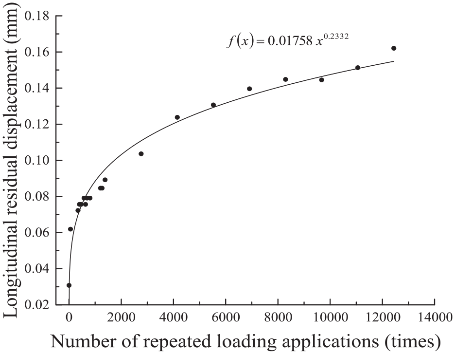
According to the test results, The fasteners 1st, 57th, 345th, 403th, 461th, 518th, 576th, 633th, 691th, 806th, 1209th, 1267th, 1382th, 2764th, 4147th, 5529th, 6912th, 8294th, 9676th, 11059th, and 12,441th times load displacement curves were obtained (Figure 5), and the corresponding cumulative longitudinal displacements of the rail against loading times were extracted and plotted in Figure 6.
Since the maximum load value applied in this repeated loading test is 20 kN, which is less than the maximum longitudinal resistance of fastener, it implies that the fastener is always in the elastic deformation stage during loading, and the cumulative displacement of fastener and the maximum longitudinal cumulative displacement are both small.
It can be seen from Figure 8 that under the same cyclic loading, the longitudinal displacement of fastener increases with the increase of the load value and the relationship between the two above is approximately linear. With the increase in the number of cyclic loads, the maximum longitudinal displacement of rail gradually increases. The growth rate of rail displacement (the slope of the displacement-load curve) increases significantly when the number of cycles is small. While, when the number of cycles increases, the growth rate of displacement gradually decreases.

The longitudinal displacement of rail under repeated loading.
As is showed in Figure 9 that before the ultimate resistance of fastener is reached, the cumulative effect of the rail’s displacement does exist. The cumulative displacement of rail increases with the increase in the number of load actions, but its growth rate gradually decreased.

The relationship between cumulative displacement and the number of load actions.
Fitting analysis of rail longitudinal cumulative displacement
The cumulative longitudinal displacement of rail under different cycles is shown in Table 1. It can be seen that the displacement of rail increases with the increase in the number of cyclic loading. In the first load, the cumulative longitudinal displacement of rail is 0.0308 mm. When loaded at the 57th time, the longitudinal cumulative displacement of rail is 0.0619 mm; At the 12,441th time, the longitudinal cumulative displacement of rail reaches 0.1620 mm, and the maximum longitudinal displacement during loading is 0.497 mm (the load value is 20 kN).
Longitudinal cumulative displacement of rail under different cycles times.

During the entire test period, the maximum longitudinal displacement and the cumulative displacement when rail is loaded are small, and the rail displacement will not exceed the limit under the existing loading times. While in actual engineering, the number of load actions will continue to accumulate with the increase in train operating time. In order to obtain the change law of the longitudinal displacement of fastener under long-term loading, the test data is specially fitted to obtain the functional relationship between the cumulative longitudinal displacement of rail f (x) and the number of cycles x is shown in formula (1):

Then the longitudinal displacement of rail under a larger number of repetitions is obtained. The coefficient of fit of this formula is 0.9351, which has a high degree of fit and a great degree of credibility. The fitted curve is shown in Figure 10.
Fitting curve of the longitudinal cumulative displacement of rail-the number of loading.
It can be seen from the fitting curve that the cumulative longitudinal displacement of rail increases with the increase in the load loading times, and the displacement growth rate gradually slows down, while the displacement tends to be stable.
Calculation of cumulative rail displacement based on fitting formula
According to the fitting formula, the cumulative longitudinal displacement of rail after the repeated action of 20,000 times, 25,000 times, 50,000 times, 100,000 times, 200,000 times, 400,000 times, and 800,000 times of longitudinal load were calculated (Table 2). The cumulative longitudinal displacement was combined with the test data to draw the rail cumulative displacement-loading times curve (Figure 11), which can be used to predict the cumulative displacement of rail after a large number of trains braking loads.
Cumulative displacement of rail under different cycles.

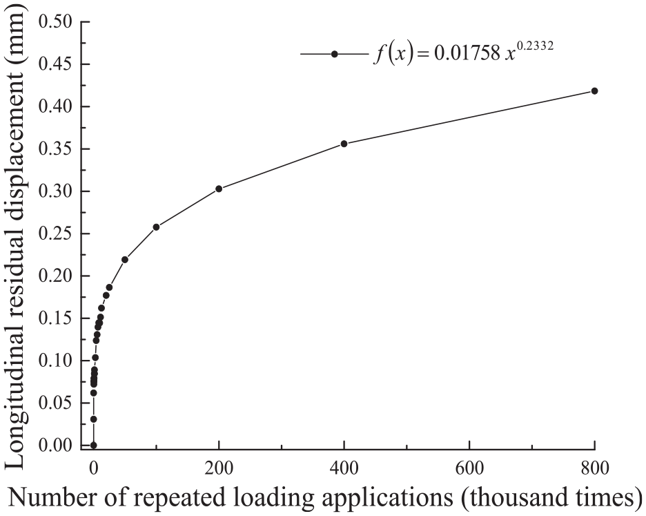
Curve of longitudinal cumulative displacement of rail at Fastener under repeated loading versus cycle times.
It can be seen from Table 2 and Figure 11 that:
When the number of load cycles is 20,000, the longitudinal cumulative displacement of rail is 0.1770 mm, and the longitudinal displacement increases slowly with the increase of the number of cycles. When the number of cycles increases to 800,000, the cumulative displacement of fastener reaches 0.4184 mm. After repeated loading, the increase rate of the cumulative displacement will gradually decrease and reach a relatively flat stage.
Rail loading analysis after repeated loads
The effect of repeated loads on the longitudinal resistance of fastener
As is showed in Figure 8 that after multiple repeated loads, many fastener parameters have changed such as the fastener ultimate longitudinal resistance. Therefore, in order to more comprehensively study the rail displacement when fasteners are loaded with repeated loads, and to obtain the longitudinal stiffness of fastener and the maximum longitudinal displacement of rail while loading, it is necessary to consider the effect of a large number of repeated loads on fastener longitudinal resistance-rail displacement characteristic curve.
Longitudinal resistance-displacement performance tests of fastener were respectively carried out at the beginning and at the end of the repeated loading cycle to obtain the effect of repeated loads on the longitudinal stiffness and longitudinal resistance of fastener. These tests were repeated four times. The results of the first test were discarded, and the longitudinal resistance of fastener was gained by the average value of the last three times. The two sets of test figures before and after repeated loading are plotted as a graph (Figure 12).

The longitudinal resistance-displacement characteristics of fastener before and after repeated loading.
As shown in Figure 12 that after 12,441 times of repeated loading, the stiffness of fastener, the maximum longitudinal resistance and the sliding resistance of fastener have increased, while the elastic displacement has decreased.
Before the experimental loading, the maximum longitudinal resistance of fastener was 23.11 kN, the sliding resistance of fastener was 21.99 kN, and the elastic-plastic limit displacement was 0.4933 mm. After loading, the maximum longitudinal resistance of fastener increased to 24.30 kN, the sliding resistance of fastener increased to 23.22 kN, and the elastic-plastic limit displacement increased to 0.4696 mm, which implies that the maximum longitudinal resistance of fastener increased by 5.15%, the sliding resistance of fastener increased by 5.59%, and the elastic-plastic limit displacement decreased by 4.80%.
From the above analysis, such a conclusion can be drawn that the longitudinal stiffness of fastener (the slope of the curve during loading), the maximum longitudinal resistance of fastener, the sliding resistance of fastener and the maximum elastic resistance increase with the increase of repeated action times of longitudinal loads, while the elastic-plastic limit displacement of the rail decreases a little.
Loading analysis of rail longitudinal displacement after repeated loading
Since the maximum longitudinal load used for the research was 20 kN, less than the maximum longitudinal resistance and sliding resistance of the fastener, it can be predicted that fasteners will always be in the elastic phase during the entire loading period of 800,000 repeated actions. To simplify the calculation, it was assumed that fastener stiffness remains unchanged. According to the fitting formula in Section 3.4 and fastener stiffness, the maximum longitudinal displacement of rail loaded with longitudinal force of 20 kN can be obtained (Table 3) after suffering 20,000 times, 25,000 times, 50,000 times, 100,000 times, 200,000 times, 400,000 times, and 800,000 times loads. It can be seen that after 800,000 times of loading, the maximum longitudinal displacement of rail while loading is 0.7534 mm. By comparing the maximum longitudinal displacement limits of the rail in different sections, it can be judged whether the longitudinal displacement of the rail exceeds the limit at the moment of loading after repeated loads.
Longitudinal displacements of rail after repeated loading.

Conclusion
In order to study and simulate the cumulative displacement of rail caused by the frequent braking action of the train, the spring-bar type III split fastener was considered and taken as an example, and the longitudinal resistance and cumulative displacement of rail were tested and studied. The relationship between the longitudinal displacement of rail and the number of loading cycles was explored under unidirectional cyclic loading. Based on the above researches, conclusions can be drawn as follows:
The cumulative longitudinal effect of rail does exist, and its cumulative displacement increases with the increase in the number of cycles. After a large number of repeated loads, the growth rate of the cumulative displacement will gradually slow down.
For spring bar type III split fasteners, the functional relationship between the rail cumulative longitudinal displacement f(x) and the number of cycles x approximately satisfies the power exponential function form: f(x) = 0.01758x0.2332, with a high degree of fit (R 2 = 0.9351) and a great degree of credibility, thus, it can be used to predict the longitudinal cumulative displacement of rail after different repeated loads.
After the repeated action of a large number of longitudinal loads, the longitudinal stiffness of fastener, the maximum longitudinal resistance of fastener and the sliding resistance of fastener increase, but the elastic-plastic limit displacement of rail decreases a little.
The cumulative displacement of rail under different cycles can be calculated by the fitting formula, and the maximum longitudinal displacement of rail during loading can be calculated by combining the longitudinal stiffness of fastener. By comparing the limit of the maximum longitudinal displacement of rail at different loading times, it can be judged whether the longitudinal displacement of the rail exceeds the limit at the moment of loading after repeated loads.
The research results can be used to predict the cumulative displacement of rail after multiple loads and can be used to provide a reference for the railway line designers and the maintenance workers, it can also provide a test basis for the improvement of the constitutive relation between fastener resistance and displacement.
Footnotes
Declaration of conflicting interests
The author(s) declared no potential conflicts of interest with respect to the research, authorship, and/or publication of this article.
Funding
The author(s) disclosed receipt of the following financial support for the research, authorship, and/or publication of this article: The research is financially supported by Hunan Provincial Natural Science Foundation Project (2019JJ40384); Scientific Research Test Project of China Railway Corporation (Grant SY2016G001); the Fundamental Research Funds for the Central Universities of Central South University (Grant 2019zzts873), which is gratefully acknowledged by the authors.
Data availability statement
Experimental data has been presented in the context.