
Abstract
In the process of vehicle development, the unsteady simulation of thermal management system is very important. A 3D-CFD calculation model of vehicle thermal management is established, and simulations were undertaken for uphill with full loads operations condition. The steady results show that the surface heat transfer coefficient increases to the quadratic parabolic relationship. The unsteady results show that the pulsating temperatures of exhaust and external airflow are higher than about 50°C and lower than 10°C, respectively, and the heat dissipating capacities are higher than about 11%. Accordingly, the conversion equivalent exhaust velocity increased by 1.67%, and the temperature distribution trend is basically the same as unsteady results. The comparison results show that the difference in the under-hood should be not noted, and that the predicted exhaust system surface temperatures using steady velocity equivalent method are low less 10°C than the unsteady results. These results show the steady velocity equivalent method can be used to predict the unsteady heat transfer effect of vehicle thermal management system, and the results obtained by this method are basically consistent with the unsteady results. It will greatly save computing resources and shorten the cycle in the early development of the vehicle thermal management system.
Keywords
Introduction
Vehicle thermal management is essential for many of the performance of the car, such as vehicle energy saving, extending life, reducing emissions, ensuring the safe operation of key components, and driving safety.1,2 Vehicle thermal management reduces the generation and displacement of heat inside and around the vehicle by adopting effective and enhanced systems and methods. Thus, the fuel economy, safety, reliability, and thermal comfort of passengers can be improved directly or indirectly.3,4
In the past few decades, numerical fluid and heat transfer technology have made rapid progress in engineering application, which has played a good role in promoting all aspects of vehicle heat management. With the entry of cars into thousands of households, the personalized demand for automobile performance and appearance is increasing. The whole society pays attention to the fuel consumption of cars and its impact on the environment, as well as the increase of electric, automatic, and driver-less vehicles. It is more and more important to improve the performance of vehicle thermal management system by using numerical fluid and heat transfer technology in the early development of vehicles.5–10
When the traditional reciprocating engine works, the total energy produced by fuel combustion is generally only about 1/3 through the piston to convert into effective power, and the other 1/3 takes the heat to the radiator after cooling water, and then dissipates the heat to the under-hood through the cooling fan, which affects the thermal environment of the under-hood. The remaining total energy is discharged from the surrounding car through the exhaust system, especially the thermal environment affecting the chassis of the vehicle. The main heat source of the under-body comes from the heat dissipation of the exhaust system. The high temperature exhaust gas after each cylinder is collected to the exhaust main through the exhaust manifold and connected to the catalytic converter, then through the resonator, then flows into the muffler, and finally discharged into the atmosphere through the exhaust tail pipe. In fact, in addition to working energy, about 70% of the engine energy needs to be protected by an effective thermal management system to achieve energy saving, and to improve the thermal comfort requirements of passengers.1,11–13
The high temperature of engine exhaust will affect the exhaust system components and their surrounding environment by heat dissipation. When the parts are too close to the high temperature exhaust system, these components will overheat. At the same time, when the cooling air after the radiator passes through the nearby heating element, such as the exhaust manifold, it will absorb the heat quickly again, and then enter the cooling system again, which makes the thermal environment worse and worse. 14
Due to the periodicity of the engine working process, the different cylinders of the same engine do work in turn, the timing of each cylinder valve is inconsistent, and the exhaust valve is not consistent at the time of opening and closing in the cylinder, which makes the exhaust gas in the exhaust manifold pulsating, and the exhaust gas is generally high temperature, the exhaust gas is generally turbulent, and even in the moment the exhaust valve is opened, the Mach number will exceed 0.3, but the time is very short, in general, the calculation is simplified to uncompressed flow. However, even after it is imported into the main pipe, the exhaust flow still has a certain periodic pulsation, which will lead to the enhanced heat transfer of the exhaust system. 15
There are many researches on vehicle thermal management system based on 3D computational fluid dynamics (CFD).There are two main approaches to these studies.
The first method is based on the temperature prediction of the temperature of the exhaust pipe of the engine, which is still a testing driving process, and the surface heat flow data of the exhaust pipe as measured by the experiment is used as the boundary condition of the CFD simulation. In the literature, several examples of heat transfer in a vehicle can be found, both of which are modeled using CFD software.16,17 Bendell studies on the entire vehicle scale, a most detailed vehicle thermal analysis model is proposed to predict the effect of temperature on its thermal shield, In this paper, the steady-state analysis of a certain vehicle in the towing test of a trailer is simulated, and the accuracy of the thermal problem of the whole vehicle is considered in the simulation study. Bendell18,19 couples a CFD model to a thermal model that simulates the qualitative data useful in the vehicle base, particularly in the area after the exhaust. Since its work in 2005, Bendell has developed a more accurate common simulation program and uses the model validation tool. With the development of the early computer-aided design (CAD) model of the vehicle, the simulation of the aerodynamic performance of the vehicle can help the model design of the automobile, because the optimized CAD data amount can be accurately provided by the CFD simulation, including the open grid, the bottom surface, the bottom body and the upper body surface. The vehicle model was analyzed by Skea et al. 20 with FLUENT software, but no correlation between the simulated surface temperature and the test data was published. It is clear that this approach is not possible for the development of new models that are out of the existing database range. A method for predicting the surface temperature of the exhaust system of a diesel engine is designed by Laurent, and the simulation results are compared with the experimental results, and the method realizes one-dimensional regeneration model and three-dimensional CFD model of the convection coefficient. The results of the analytical model and the CFD model are applied to the three-dimensional finite element analysis (FEA), and the surface temperature distribution is determined. But Laurent 21 did not take into account the pressure drop of the exhaust system, that is, the influence of back pressure was reduced.
The second method is to simulate the surface temperature of engine exhaust system by fluid-solid coupling heat transfer method. However, in many of these CFD coupling simulations, most models do not include radiation.22–24 In the absence of radiation in the model, experimental data and additional assumptions of uniform temperature are generally needed to input the temperature into the 3D CFD model. However, the temperature in most areas of the engine exhaust system is higher than 300°C, and the temperature is higher at the hot end of the exhaust system. It is clear that radiation heat transfer is the main heat transfer mode between the exhaust system and the components close to it. Mukutmoni et al., 25 simulated the bus coupling simulation under different driving conditions, such as large speed change, engine idle speed and unused engine cooling. The coupling fluid-thermal solver takes into account radiation. The simulated temperature is in good agreement with the actual experimental results. The simulation results also show the influence of exhaust heat, but these simulations do not simplify the exhaust pipe to constant temperature heat source, 25 but can be simulated more accurately by including the transient temperature associated with the exhaust hot gas. Therefore, it is necessary to calculate the transient heat transfer of automobile exhaust system as accurately as possible. The unsteady heat transfer simulation caused by the engine exhaust system has become an important part of the automobile development process.21,25
Chen et al. 26 combines RadTherm software with FLUENT model, and proposes a transient analysis method for vehicle thermal management calculation. The temperature curves of thermal load varying with different working conditions are obtained by simulation. The comparison between the simulation results and the experimental results shows that the transient thermal analysis of vehicle thermal management is feasible.
To sum up, for full vehicle thermal management systems with complex structures, which includes the thermal conduction and radiation heat transfer of heat parts of automobile strains, the high temperature exhaust pulsation convection and radiation heat transfer, convective heat transfer of cooling air. At the same time, there is a gas-solid two-phase flow coupling heat transfer effect. Predicting the heat transfer characteristics of the changes with variable engine and vehicle conditions poses a great challenge for reducing computational resource allocation, reducing time-consuming, and reduced development cycle requirements.
The main organizations of this paper are as follows: first, the next part a 3D-CFD calculation model of vehicle thermal management system is established and described in detail. Second, the simulation results of vehicle thermal management system through steady, unsteady, and steady velocity equivalent simulation are obtained and discussed. The third is to compare the results of steady, unsteady and steady velocity equivalent methods, and finally draw the conclusion of the paper.
Computational model
Computational domain and Mesh model
The whole vehicle thermal management system model comprises an air inlet module, an engine compartment, a heat shield, a ground, a side wall, a tunnel, a dash, a bottom plate, an oil tank, an exhaust pipe, a resonator, a silencer, a tire basin, a rear suspension and other subsystems, in which the structure and components of the engine exhaust system are designated as shown in Figure 1.

The structure and components naming of the engine exhaust system.
Figure 1 shows that after the front and rear exhaust manifolds (uh-Mani-f and uh-Mani-r), the high temperature exhaust of the engine flows into the front and rear catalytic converter (uh-converter-f and uh-converter-r) through the exhaust pipes, and the exhaust of the front and rear catalytic converter flows into the resonator 1(ub-resonator-1) through the exhaust pipe 1 (ub-pipe1) and pipe 2 (ub-pipe2), then the exhaust flows into the resonator 2(ub-resonator2) through the exhaust pipe 3 (ub-pipe3), and then it flows into the muffler(sub-muffler) through the exhaust pipe 4 (ub-pipe4), Finally, the exhaust gas of the engine is discharged into the external atmosphere through the exhaust tail pipe (ub-tail-pipe).
In the analysis of vehicle thermal management, the surface data of car model are provided by CAD data and Hyper Mesh model. The structure of vehicle thermal management system is complex, there are many solving equations, and the number of computing domains and grids is huge. Due to the limitation of computer resources in the past few decades, CFD analysis for automobile thermal management is usually divided into three independent regional simulations: front end, under-hood and under-body. The boundary conditions of these sub-models either come from experimental data or from experience or the calculated average value of subsystems.
However, in our calculation, all three subsystems of vehicle thermal management such as the front end, the under-hood and the under-body are taken into account, and the solid structure of the after treatment equipment of the exhaust system and the internal exhaust gas of the exhaust system are also added, including all the components in a typical vehicle thermal management model that are larger than or equal to 80 mm, which totally contains more than 180 components, and the structure of the whole heat management model is very flexible. If you want to change the layout or add new components, as long as they are important components for vehicle heat management, they can be easily added to the model.
The vehicle model has a length of 4800 mm, a width of 1600 mm, and a height of 1540 mm.In order to obtain the accuracy of the calculation results, the vehicle model is placed in a numerical wind tunnel with a length of 35 m, a width of 16 m, and a height of 10 m, the distance between the front of the car and the boundary is 1.5 times the length of the car, and the width direction is symmetrical, and the computational domain is constructed. Figure 2 shows the car model and computational domain used in the simulation.

The car model and computational domain.
The size of the computational domain and the complexity of the surface determine the total number of volume grids of the model. In the current vehicle model, the shape of the automobile parts is complex, and there are many surfaces, especially the outer surface of the automobile. In hyper mesh software, the triangular mesh is used to discrete the surfaces of each component, and the size of the triangular mesh varies with the change of the surface complexity of the vehicle parts. The surface of the parts in the sensitive area to the grid is divided into 8 mm × 15 mm mesh, and a total of more than 360,000 surface elements are used, the quality of the surface mesh is modified by controlling the skewness of 0.8 for the surface mesh. The tetrahedral mesh is used to discrete the air computing domain outside the vehicle, and the mass of the volume grid is modified by controlling the skewness of 0.95. This triangular/quad mesh structure, which is used for the discreteness of surface/volume, can quickly and conveniently represent the complex geometry that often occurs in automobile. The type and the number of grids in each part are as shown in Table 1, and the cross-section mesh is shown in Figure 3.
The type and the number of grids in each part.

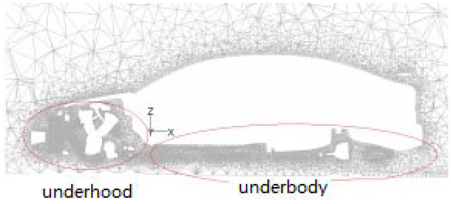
The cross-sectional (y = 0) mesh in the vehicle.
Table 1 shows that there are about 2.85 million tetrahedral grids were used for the external airflow, more than 300 thousand tetrahedral grids were used for the fan airflow(MRF), more than 90,000 tetrahedral grids were used for the airflow (porous medium) of heat ex-changers (condenser and radiator), more than 150,000 cells were used for the exhaust (fluid), In addition, some 110,000 solid grids were used for the gas-solid coupling heat transfer calculations, and a total of about 3.5 million cells were used in the current thermal management system simulation.
Figure 3 shows that the grid density in under-hood, under-body, and the surface and wake area of the car body is large, so the grid in the corresponding area can be encrypted according to the needs of accuracy.
Heat ex-changer and fan models
Since the vents on the heat ex-changer are very small, and its performance depends mainly on the cooling air flux and temperature which flowing through the core of them, in order to save computing resources, the condenser and radiator are simplified from the effects of them on the flow field and the temperature field, and they are treated as porous medium. From a flow perspective, they are considered as a resistance to the cooling air flows, that is, a loss of pressure when the cooling airflow through the condenser and radiator, and they are considered as a heat source per unit volume from the point of view of the temperature field and heats the airflow from the engine cooling system and the vehicle air conditioning system, which depending on the mass flow rate and import and export temperature of the air and cooling water flowing through the condenser and radiator.
According to the curve of the change of the wind speed and the data of the heat exchange performance curve provided by the respective suppliers of the condenser and the radiator, the heat transfer of condenser and radiator is estimated. The above-mentioned parameters are changed into the subroutine SORENT in the Star-CD (or the UDF in FLUENT) and added to the fluid energy equation in the form of a source item, indicating the effect of the heat ex-changer and the fan on the fluid field and the thermal field.2,23 The performance of the program is judged by monitoring the speed and the temperature of the condenser and the radiator in the calculation, and the simulation is stopped only when the periodic pulsation rule of the results is obtained.
The muti-reference coordinate system (MRF) method is used for the description of fan flow. According to the wind speed curve and the rotation speed parameter provided by the fan supplier, the air volume of the fan is estimated.2,23
Governing equations and numerical methods
The steady, unsteady, and steady velocity equivalent simulations were undertaken for uphill with full loads operations condition. In this simulation, the governing equations of flow and heat transfer 27 as follows equation (1):

Where ϕ is the flow parameter and Γϕ is the diffusion coefficient, when ϕ = 1, Γϕ = 0, the equation (1) is a continuity equation; when ϕ = u, v, w. Γϕ = μ, respectively; the equation (1) is the momentum equation in the direction of x, r, and θ, respectively; when ϕ = k, ε, Γϕ = μ e /σ k ,μ e /σ e , respectively, and the equation (1) is the k–ε equation, respectively.
For solid components, only energy equations are generally solved. In the solution of thermal management system, only convective coupling and radiation heat transfer are considered on the surface of solid components of exhaust system. Turbulence model selects the two equations k–ε of high Reynolds number, the coupling for pressure, and velocity SIMPLE algorithm is used in steady and steady velocity equivalent simulation, PISO algorithm is used in unsteady simulation, thermal conduction, and convection heat transfer are described by the thermal convection and convection heat transfer coefficient, radiation heat transfer using DO model, ignoring the solar radiation effect. The temperature field chooses the second-order spatial discrete format (MARS), the rest are using the first-order orientation style (UD), the residual item of the convergence standard energy equation is <10–6, and the remaining items are <10–3.
For time-dependent calculation of 3D CFD conjugate model, especially the calculation of unsteady heat transfer, large calculation capacity is required. 23 The effective utilization of computing resources not only ensures the performance and accuracy of the simulations, but also shortens the calculation time and improves the calculation efficiency of these simulations. In this paper, the 3-D CFD unsteady thermal management calculation is carried out on a high performance parallel computing workstation. Its basic configuration is 2 CPU and 32 threads, and 128 G memory.
Boundary conditions
There are several boundary types, such as velocity inlet and outlet, solid wall (wall), internal circulation surface, baffle, etc. Solid wall and baffle are set to smooth, non-slip, impermeable wall surface, which given the solid material and thermal physical properties, during the thermal analysis, the thermal conductivity of the solid is set 23.6 W/(m·°C). Two to ten millimeter for exhaust pipe thickness, wall heat exchange mode for conduct.
The parameter values of the specific boundary conditions under the condition of full-load uphill operations conditions are summarized as following Table 2.
The parameter values of the specific boundary conditions.

※, Exhaust temperature: 700°C, exhaust mass flux is estimation value of full throttle.
The concentration of the following emission gases emitted by the engine is as follows: CO < 0.2%, HC < 0.1%, NOx < 0.25%, SO2 < 0.008%, and the concentration of these gases adds up to <0.56%, and the molecular weight of most gases is not much different from the air, 28 so the composition of the exhaust and further reactions are not taken into account.
The model only gives the heat transmission boundary conditions for the main heat-affected components of the engine compartment and exhaust system (especially the engine head and cylinder block, the oil pan, transmission, compressor exhaust manifold, catalytic converter, and muffle, etc.) and the zero-thickness wall (shadow or baffle) such as the heat shield, as shown in Table 3.
Heat transmission boundary conditions.

In the absence of a corresponding database, the thermophysical properties (thermal conductivity, heat ratio, density, radiation rate, etc.) of the important heat-affected component materials of the engine compartment and exhaust system are obtained mainly by querying the relevant literature and teaching materials. This paper mainly draws on the parameters provided in literature,23,27–29 the exhaust system components are made of aluminum alloy, the other components are stress steel, and the heat shield is insulated, and the surface roughness is all 32 micron.
The heat dissipation or temperature of its surface (especially the exhaust manifold, engine surface, oil pan, or temperature) is mainly estimated; Heat dissipation, such as condensers and radiators, can be obtained based on performance curves. The exhaust periodic pulsating movement were given as follows equations (2) and (3):


where,
On the basis of steady state simulation under the condition of full load vehicle uphill, 13 the time step of unsteady simulation is determined according to the engine speed, and the fluctuating velocity and temperature of exhaust gas are determined according to the exhaust law of the engine at the corresponding speed. The subroutine U File (UDF), which can be called by Star-CD (FLUENT) software,28,29 is written as the boundary conditions of unsteady simulation, respectively.
Results of heat transfer and discussions
Based on the above-mentioned calculation model of the vehicle thermal management system, the steady and steady method and the corresponding boundary condition are respectively adopted, and the thermal speed coupling and the radiation effect of the vehicle thermal management system under the condition of full load climbing are simulated by using Fluent and Star-CD software. The unsteady simulation is that under the condition of steady simulation and convergence, the constant speed of the tail gas of the engine is changed to the pulse speed, and the normal temperature is changed to a pulsating temperature, and the results of the analysis presented in the form of a chart and a table are respectively given, and the corresponding discussion is carried out. Based on the results of steady and unsteady simulation and the time-consuming calculation, the effects of heat transfer are analyzed, and the results of three simulation methods are compared.
Results of steady heat transfer
The analysis was carried out for uphill with full loads operation conditions, which the speed of the vehicle is 36 km/h, and the engine and fan speed are 3000 rpm.
The velocity vectors in the symmetric plane (y = 0 m) and the pressure contours in the plane parallel to the underground (z = 0.15 m) are given by steady-state simulation, as shown in Figures 4 and 5, respectively. In order to better explain the front-end, under-hood, and under-body area of the air flow characteristics.
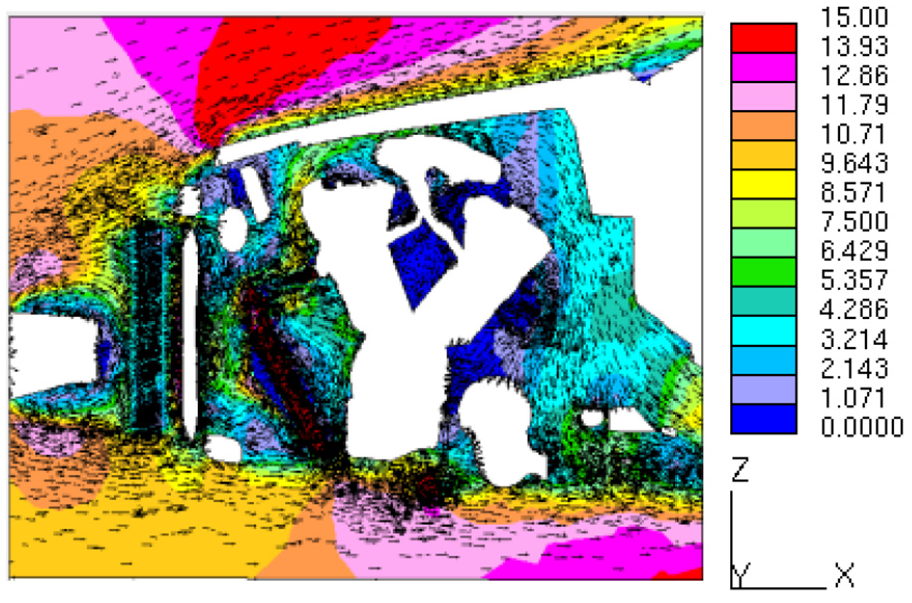
Velocity vectors of y = 0 plane in under-hood.

Pressure contours of z = 0.15 m plane.
Figure 4 shows the predicted cooling airflow velocity varies from 0 to about 15 m/s, due to the extrusion of its airflow space and the decrease of pressure, the maximum local speed appears at the top of the vehicle. The average speed in under-hood is about 5 m/s, which is much higher than that caused by thermal buoyancy. Even if the vehicle is in idle state, although the speed becomes smaller, because of the lower engine load, it produces less heat, and the speed caused by thermal buoyancy is smaller. Even if only the fan causes the lower cover airflow velocity is still greater than the speed caused by buoyancy. Similarly, if the vehicle speeds up, the contribution of the speed caused by thermal buoyancy to the velocity field at the bottom of the body is negligible. Generally speaking, for under-hood thermal environment, when the fan is turned on, the buoyancy contribution can be ignored. For under-body thermal environment, when the vehicle has a certain speed, the buoyancy effect will be ignored, but in the case of idle speed, the influence of thermal buoyancy on the thermal environment of under-body is a problem worthy of study.
As can be seen in Figure 5, when the vehicle speed is 36 km/h, fan in the power supply state of 3000 rpm, the fan instead of the source of pressure rise, that is to say, the wind grinding effect is worth noting. Only at this speed, the pressure loss caused by wind grinding is very small, often in the range of 5–10 Pascal, the dynamic head caused by vehicle movement is about 110 Pascal, and the pressure loss caused by heat ex-changer is about 70 Pascal.
The temperature contours distributions in the same range of 40°C–120°C in the symmetric plane (y = 0 m) and in the plane parallel to the underground (z = 0.15 m) are given by steady-state simulation, as shown in Figure 6 for the computational domain configurations. In order to better explain the thermal environment in the front-end, under-hood, and under-body area.

Temperature contours of y = 0 m and Z = 0.15 m plane.
Figure 6 shows that the average temperature of under-hood airflow is higher than about 85°C at uphill with full load operation conditions, which is due to the high power of the engine and the large exhaust gas emission. The results show that the surface temperature of exhaust system components increases with the result of high temperature exhaust gas radiation and coupling heat transfer, which leads to the temperature of the exhaust system and its surroundings are higher from the exhaust manifold through ternary catalytic converters, resonators, and muffler, and the temperature on the right side of the exhaust tail pipe is slightly higher than that on the left side of the exhaust tail tube. This is a great challenge to the heated components, electronic components and fuel pipeline systems in under-hood and under-body. In order to protect the exhaust system and the parts around under-body from the influence of radiation heat, thermal coatings should be used to protect them. These results also show that the hot end thermal environment of the exhaust system is the key to the uphill of the automobile under the full load condition, and the cold end thermal environment of the exhaust system is effectively improved at the higher vehicle velocity and the higher fan speed.
Results of unsteady heat transfer
On the basis of simulating the steady heat transfer characteristics of a vehicle thermal management system under full load, the transient heat transfer characteristics are simulated according to the law of engine exhaust speed and temperature fluctuation, and the results of coupled heat transfer analysis of unsteady flow field and gas-solid two-phase flow are given in graphic form.
To better illustrate unsteady vehicle thermal environment, the temperature distribution of the symmetry plane (y = 0 m) and the plane parallel to the ground (z = 0.15 m) in the time interval from 0.5 to 0.6 s was selected in the simulation results, and in order to facilitate the comparison of the results, only the temperature contours in the same range from 40°C to 120°C are shown in Figures 7 and 8, respectively.

Temperature of y = 0 m plane in a circle.

Temperature of Z = 150 mm plane in a circle.
As shown in Figures 7 and 8, the simulation results show that when the exhaust gas velocity fluctuation is 10% or the exhaust gas velocity pulsation is 10% and the temperature fluctuation is 1%, the average temperature fluctuation value of the engine internal exhaust gas is more than 50°C, and the average pulsation value of the external cooling air flow temperature of the vehicle is <10°C, which indicates that the periodic pulsation of the engine exhaust gas exhaust volume in the engine cycle has a great influence on the temperature fluctuation of the exhaust system itself. It also has a great influence on the thermal environment around the exhaust system, so it is necessary to pay attention to the safety of high temperature components around the exhaust system. However, it has little effect on the external air flow temperature and the thermal environment far away from the exhaust system. The qualitative trend of flow field and thermal field of vehicle thermal management system given by these analyses is basically reasonable.
Heat transfer results of steady velocity equivalent method
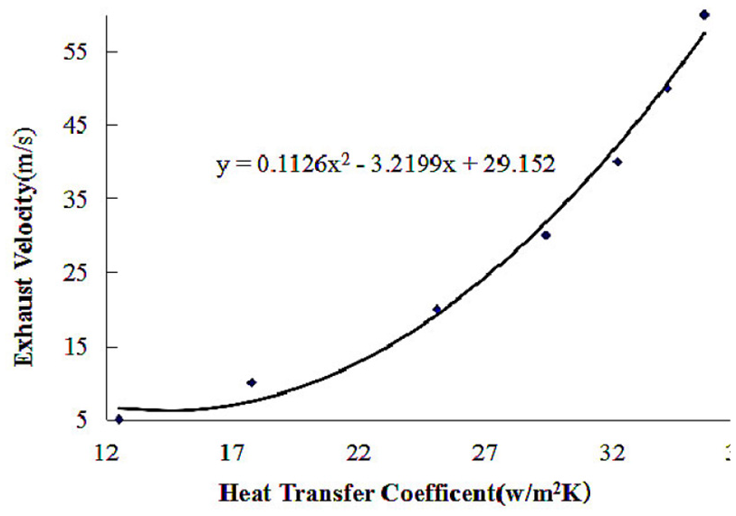
It can be obtained the change of heat transfer coefficient with the velocity of the exhaust from the previous steady state calculation, it can also be fitted out the relationship curve between heat transfer coefficient and internal flow velocity, and explored their relationship, and this relationship is transformed by a reverse function, the exhaust velocity will be obtained under the corresponding heat transfer coefficient, as shown in Figure 9. To better illustrate the differences between the unsteady and steady results, the heat dissipating capacities of steady, and unsteady average value on the surface of each component of exhaust system with the periodic fluctuation of exhaust velocity and temperature is given, as shown in Figure 10.
Heat transfer coefficient varies with exhaust velocity.

Heat dissipating capacities comparison of steady and unsteady average value.
As shown in Figure 9, the change of engine exhaust emission displacement with the change of engine operating conditions, the corresponding change of surface heat transfer coefficient of the exhaust system components, the simulation results show that: based on the established fixed calculation model, when the velocity of engine exhaust increased from 5 to 55 m/s, the heat transfer coefficient of the exhaust system surface from 12 W/m2·k increased to 37 W/m2·k, the fitting function basically shows the growth of the secondary parabolic relationship, if the heat transfer coefficient is obtained by unsteady simulation, the corresponding steady equivalent exhaust velocity can be obtained through the above fitting function.
As shown in Figure 10, when the engine exhaust velocity pulse value is 10%, the unsteady average surface heat dissipating capacities of the exhaust system components is about 10.6% higher than that of the steady results, and when the engine exhaust velocity pulse value is 10% and the temperature pulse value is 1%, the unsteady average surface heat dissipating capacities of the exhaust system components is about 11.6% higher than that of the steady results. The results also show when the effects of engine exhaust speed or speed and temperature fluctuation are taken into account, the unsteady average surface heat dissipating capacities of each part of the exhaust system is higher than that of the steady state except ub-pipe4.when the engine exhaust velocity pulse value is 10%, except ub-pipe1, ub-pipe 2, and ub-pipe 4, the mean surface heat dissipating capacities with 1% pulsating exhaust temperature are almost the same as the mean results without pulsating exhaust temperature. The reason for this is that there are not enough contact time between gas and exhaust system components, resulting in heat transfer limitation when the temperature of exhaust increase as engine speed increases.
As shown Figures 9 and 10, at the full loads uphill condition, the surface heat dissipation of the exhaust system during the consideration of exhaust pulse-enhanced heat transfer increased by about 11%, and the conversion steady equivalent exhaust velocity increased by 1.67%, that is, It increased from the original 78 g/s to about 79.3 g/s, to keep other conditions unchanged, the thermal management system is simulated with steady velocity equivalent, and the temperature field distribution trend obtained by the simulation is basically the same. It is shown that the steady velocity equivalent treatment method can approximately simulate the unsteady heat transfer enhancement effect of vehicle thermal management system caused by exhaust pulsation, and the specific results will be further compared and analyzed in the following description.
Results comparison and analysis
Temperature comparison of front-end CRFM
In order to better explain the thermal environment difference in the under-hood by the three different simulation methods, the average temperature of vehicle front-end CRFM (condenser, radiator, and fan module) in Table 4.
Average temperature comparison of vehicle front-end CRFM [°C].
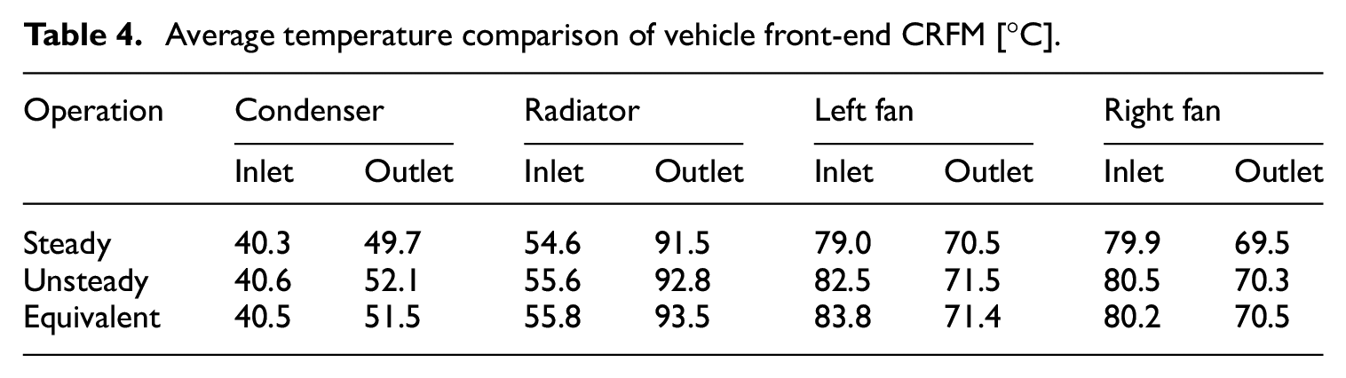
Table 4 shows that the average condenser inlet temperature at uphill with full loads conditions is about 40.3°C, 40.6°C, and 40.5°C using steady, unsteady, and steady equivalent simulations, respectively. The temperature at uphill with full loads conditions are higher than the ambient temperature (40°C), it’s because air re-flux occurs at the top of the condenser, radiator, and fan module (CRFM). Overall, the issue of front-end air re-flux is not very serious.
After the cooling air passes through the condenser and radiator, the average temperature is about 91.5°C, 92.8°C, and 93.5°C by steady, unsteady and steady velocity equivalent simulation, respectively. The main reasons for the difference in the average temperature at the radiator outlet are as follows: One is the difference of mass flow rate of engine exhaust in different cases, which leads to the worse thermal environment at the hot end of exhaust gas, and the cooling air temperature entering the radiator is increased by air recycling. The mass flow rate is 78 and 79.3 g/s using steady and steady velocity equivalent simulations, respectively. The other different cause is the unsteady enhanced heat transfer effect using different simulations, at steady, and steady equivalent conditions, they are not regarded as pulsating to enhance the role of heat transfer, whereas it is necessary to consider the role of exhaust pulsation to enhance heat transfer. There is an only 0.7°C difference of the outlet average temperature of the radiator using unsteady and steady velocity equivalent simulation, respectively. When the difference of under-hood thermal environment is <1°C, the influence on many thermal management components can be ignored, that is to say, the thermal environment of under-hood is not worthy of attention.
Temperature comparison of exhaust system surface
To better illustrate the differences between the steady, unsteady, and steady equivalent results, Figure 11 shows the average temperature on the surface of each component of the exhaust system, and compares the results of the unsteady average value with the steady and steady velocity equivalent methods.

Comparison of surface temperature of exhaust system under three simulation methods.
As can be seen in Figure 11, at the unsteady (with 10% pulsating velocity and 1% pulsating temperature) of exhaust condition, the unsteady mean surface temperatures of almost all exhaust system components are higher about 40°C than the steady results. The results show that the impact of the 10% pulsating exhaust velocity to surface temperatures of exhaust system components are pretty obvious. The results also show that the predicted surface temperatures of almost all exhaust system components using the steady equivalent method are low less 10°C than the unsteady results.
The unsteady average surface temperature of almost all components of the exhaust system is about 40°C higher than the steady results when the amount of the velocity pulsation of engine exhaust is 10% and the amount of the temperature pulsations of engine exhaust is 1%. The results show that the effect on the surface temperature of the components of the exhaust system is quite obvious when the amount of the velocity pulsation of engine exhaust is 10%. The results also show that the surface temperature of almost all of the components of the exhaust system predicted using a steady state or the like is 10°C lower than the non-steady-state result, and the maximum temperature difference on the ub-muffler is about 20°C, and the error is 7.4%, mainly because the pulsation-enhanced heat transfer in the muffler is more obvious. The above results shown that this equivalent treatment method can be used to estimate the unsteady heat transfer effect of the automobile heat management system caused by the exhaust pulse, and the results obtained by this method are basically consistent with the actual unsteady calculation results, which can greatly save the calculation resources and shorten the product development cycle.
Conclusions
A full vehicle thermal management systems model was established, and the heat transfer characteristics of the steady and the unsteady thermal management system are simulated respectively. On this basis, the steady velocity equivalent method is proposed to simulate the unsteady heat transfer characteristics. Some conclusions based on the model above are as following.
The steady results show that the under-hood thermal environment is critical for the uphill with full loads operating condition, and when the velocity of engine exhaust increased from 5 to 55 m/s, the heat transfer coefficient of the exhaust system surface from 12 W/m2·k increased to 37 W/m2·k, the fitting function basically shows the growth of the quadratic parabola relationship.
When the exhaust gas velocity fluctuation is 10% or the exhaust gas velocity pulsation is 10% and the temperature fluctuation is 1%, the average temperature fluctuation value of the engine internal exhaust gas is more than 50°C, and the average pulsation value of the external cooling air flow temperature of the vehicle is <10°C, and the average heat dissipation capacity of each component of the exhaust system is increased by 11.6%.
During the consideration of exhaust pulse-enhanced heat transfer increased by about 11%, and the conversion equivalent exhaust velocity increased by 1.67%, that is, From the original 78 to about 79.3 g/s, the thermal management system is simulated with steady velocity equivalent method, and the temperature distribution trend is basically the same as with unsteady simulation.
The comparison results of using steady, unsteady, and steady velocity equivalent simulations show that the thermal environment difference in the under-hood should be not noted, and that the predicted surface temperatures of almost all exhaust system components using the steady equivalent method are low less than 10°C than the unsteady results. The above results show the steady velocity equivalent method can be used to predict the unsteady vehicle thermal management system caused by the exhaust pulse, and the results obtained by this method are basically consistent with the actual unsteady calculation results, simulations such as these can greatly save the calculation resources.
Footnotes
Declaration of conflicting interests
The author(s) declared no potential conflicts of interest with respect to the research, authorship, and/or publication of this article.
Funding
The author(s) disclosed receipt of the following financial support for the research, authorship, and/or publication of this article: This work was partially supported by the National Natural Science Foundation of China (Grant No: 51975220, 51809236), Natural Science Foundation of Guangdong (Grant No: 2019B151502057)and the Guangdong Basic and Applied Basic Research Foundation (2021A1515010794), Guangdong Provincial Key Laboratory of Electronic Information Products Reliability Technology (2017B030314151).