
Abstract
Electro-mechanical braking is a new braking mode of rail vehicles, which has the advantages of compact structure, fast response speed, and high precision. It is a new braking technology that conforms to the development trend of full electrification and full intelligence of rail transit brake devices. Due to the special power demand of the electro-mechanical braking device, the electro-mechanical braking motor has a short-time and intermittent working mechanism and is in the state of blocking during working, resulting in its high-temperature rise. Therefore, it is necessary to calculate the temperature rise of the motor quickly and accurately at the beginning of its design. To address this problem, based on the coupling calculation of the equivalent thermal circuit method and the equivalent magnetic circuit method, a fast temperature rise calculation method of the motor is proposed. Then, using the fast calculation method, the temperature rise of the electro-mechanical brake motor under different working periods and wind speed is calculated. By function fitting the calculated results, the motor temperature rise curve fitting function is obtained, which can accurately predict the temperature rise of the motor under different working conditions. It provides a theoretical basis for the use of electro-mechanical braking motor in different working conditions and also provides a reference for the design of the electro-mechanical braking motor.
Introduction
Electro-mechanical Brake (EMB) is a new type of railway vehicle braking mode, which directly drives the brake pad and brake disc friction through the motor to produce braking force. EMB technology was first proposed in the aviation field,1–3 which is known as the “all-electric brake” of aircraft. Later, this technology has also been widely used in hybrid braking systems and electromechanical parking braking systems in the field of auto-mobiles.4–6 EMB technology is now used in the braking system of rail transit. The Braking Technology Research Team of Tongji University has been developing electro-mechanical braking device prototype suitable for rail vehicles since 2014.7,8 The electro-mechanical braking prototype developed by them was exhibited in the 2018 Berlin Rail Transit Technology Fair, which is part of a new generation of subway vehicles proposed by CRRC Qingdao Sifang Vehicle Co., Ltd, as shown in Figure 1.

Electromechanical devices on display at the 2018 Berlin rail transit technology fair: (a) a new generation of subway vehicles and (b) prototype of electromechanical brake device.
The train electro-mechanical braking device is a mechatronic servo system,9,10 which is composed of a permanent magnet DC motor, encoder, mechanical transmission component, and force sensor, as shown in Figure 2. In the train electric mechanical braking device, the motor is the core power component, which plays the role of converting electric energy into braking power source. In the working process of electro-mechanical braking device, the motor generates torque, and then through mechanical transmission, the clamping force is generated. To ensure persistently clamping force, the motor needs to work for a long time in a locked state, which will lead to excessive temperature rise of the motor. The motor for electro-mechanical braking is permanent magnet motor. For permanent magnet motor, too high temperature will reduce the performance of permanent magnet and even cause irreversible demagnetization, thus affecting the working stability of motor. 11 Therefore, it is necessary to accurately calculate the temperature rise of the motor at the beginning of designing the motor for electro-mechanical braking. At the same time, when the rail vehicle is running, it is braked about once every 2 min, lasting about half a minute each time. This will cause the motor to need short-term, intermittent work. Different subway vehicles, different lines, will also lead to different motor temperature rise. Therefore, a fast and accurate calculation method of motor temperature rise is urgently needed.

Transmission principle of electro-mechanical braking device.
The influence of electromagnetic field should be taken into account in the calculation of temperature field of permanent magnet motor, which is coupled with each other. In recent years, more and more researches have applied the electromagnetic - thermal coupling calculation to the design, analysis, and optimization of motors. 12 Bracikowski et al. 13 have established a model for the design of permanent magnet motor, and the centralized parameter network model was adopted for the calculation of electromagnetic field and temperature field, which realized the two-way coupling calculation of electromagnetic and heat. Traxler-Samek et al. 14 proposed a method for coupling calculation of motor loss, air flow, and temperature field, in which the equivalent thermal network was adopted for temperature field calculation. Han and Song 15 have calculated the temperature rise of the permanent magnet synchronous motors by using the method of two-way coupling of the temperature field of electromagnetic field and considering the temperature characteristics of the materials in the motor. From the current research, there are mainly two schemes for electromagnetic-thermal coupling analysis of motors, namely, unidirectional coupling of electromagnetic field-temperature field and bidirectional coupling of electromagnetic field-temperature field. Both of these two methods need to use the finite element method to carry out electromagnetic and temperature simulation. The finite element method has a higher solving accuracy, so it will be used in most of the temperature field analysis.16,17 Unidirectional coupling is to calculate the temperature field of the motor by using the loss data in the electromagnetic finite element simulation results as the heat source. In the bidirectional coupling calculation, the electromagnetic field calculation results are taken as the temperature field analysis conditions, and the temperature field calculation results are input to the electromagnetic field analysis for repeated iteration. The results of two-way coupling calculation are more accurate, but the calculation requirements are higher and it may be difficult to converge.
To solve this problem, a fast temperature rise calculation method for electromechanical braking motor based on magneto-thermal coupling is proposed in this paper. In the initial stage of calculation, we adopt the coupling iterative calculation of the equivalent magnetic circuit method and the equivalent thermal circuit method to obtain the electromagnetic performance of the motor and the average temperature rise of each part of the motor. Then, we use the one-way finite element analysis of electromagnetic field and temperature field and carry out iterative calculation to obtain more accurate temperature rise results of the motor. And we calculated the electromagnetic and temperature rise of a self-designed 16-pole 42-slot permanent magnet motor for electro-mechanical braking. Meanwhile, the magneto-thermal coupling finite element method is used to calculate the temperature rise of the motor, which verifies the accuracy of the fast calculation method proposed by us. Then, we use this calculation method to calculate the temperature rise of the motor under different working conditions, which provides a theoretical basis for the use of the motor for electromechanical braking under different working conditions, and also provides an empirical value for the subsequent motor design.
Rapid calculation method of motor temperature rise
Equivalent thermal circuit method
The main factors leading to the temperature rise of the motor are copper loss, iron loss, eddy current loss, and stray loss.18,19 Since the motor for electro-mechanical braking mainly works in the stalled state, the main temperature rise factor is copper loss. Almost all the input power is converted into heat on the motor winding in the stalled state, resulting in the temperature rise of the motor. Therefore, the highest temperature rise part of electric machinery brake motor must be winding. Considering the weight, size limit, and other factors, the motor is often integrated in the cylinder. So in the calculation of temperature rise, the structure of the cylinder is simplified as necessary components: motor stator, motor rotor, cylinder, bearing, end cover, winding, etc., as shown in Figure 3.

Simplified motor model: (a) main cross-sectional view and (b) left cross-sectional view.
The equivalent thermal circuit method is based on the principle that heat transfer is similar to circuit, the real heat source and thermal resistance are represented by heat source and resistance parameters, and then the temperature of each node is calculated by using the circuit calculation principle. 20 For electric machinery brake motor, its loss is mainly copper loss, which acts on the winding. The calculation formula of thermal resistance RT is:

Where τ represents the temperature rise of component; P is heat flux. The physical meaning of heat flow is the heat absorbed by rising unit temperature, which is expressed as:

Where CT represents heat capacity.
When the heat flows through a conductive body, the conductive body can be equivalent to thermal resistance and heat capacity, and a heat flow source can be used to equivalent the heating object. The motor for electro-mechanical braking is axisymmetric structure, ignoring the circumferential temperature change. Each part of the motor can be equivalent to a hollow cylindrical unit with the rotating shaft as the center. The equivalent thermal circuit model of the motor is shown in Figure 4.

Equivalent thermal circuit model.
In the calculation using the thermal circuit model, it is necessary to input parameter A, which is the copper loss calculated by the excitation current and winding resistance under the assumed working temperature in the equivalent magnetic circuit method. Therefore, the magnetic circuit calculation will affect the calculation of temperature. Next introduced the motor magnetic circuit calculation method.
Equivalent magnetic circuit method
Equivalent magnetic circuit method is a common and effective method in the design and characteristic analysis of permanent magnet synchronous motor.21,22 By analogy of “magnetic circuit” and “circuit,” this method constructs a magnetoresistive network model by using the magnetoresistance varying with time and space, and establishes the network equation based on node magnetic potential, the magnetic field distribution is obtained by solving the equation. Thus, we can get the static characteristics of the motor. 23
Equivalent magnetic circuit of permanent magnet
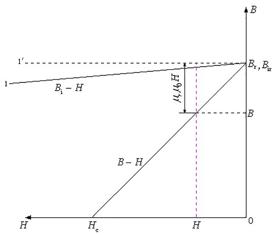
When establishing the equivalent magnetic circuit model of motor for electro-mechanical braking, the equivalent magnetic circuit of permanent magnet should be established first. In general, the permanent magnet works on the recoil line. For NdFeB permanent magnet within 100°C, its demagnetization curve is a straight line, as shown in Figure 5, which is basically coincident with the recoil line, and can be expressed as:


Where B represents magnetic induction strength; H is the magnetic field intensity; Br is the residual magnetic induction strength; Hc is the coercivity of magnetic induction intensity; u0 is the magnetic constant; ur is the recovery permeability, which can be calculated by u0.
Demagnetization curve of NdFeB permanent magnet.
In the permanent magnet motor, the output of the external magnetic circuit of the permanent magnet is manifested as magnetomotive force Fm and magnetic flux Φm. Assuming that the cross-sectional area of the permanent magnet perpendicular to the magnetization direction is Sm, and the length of the magnetization direction is hm, then the magnetomotive force and magnetic flux can be expressed as:


Combining equation (3) and equation (5), we can get:

Where
It can be seen from equation (6) that during the operation of the permanent magnet motor, the permanent magnet can be equivalent to a constant magnetic flux source Φr parallel with a constant internal permeability Λ0, which provides the magnetomotive force Fm and magnetic flux Φm to the external magnetic circuit, as shown in Figure 6.

Diagram of equivalent magnetic circuit of permanent magnet.
Equivalent magnetic circuit of external magnetic circuit
In permanent magnet motors, the total magnetic flux provided by the magnet to the external magnetic circuit can be divided into two parts: part of them is the winding coil, which is the basis of torque and speed output, known as the main magnetic flux Φδ; the other part does not form a magnetic field with the winding turns, which forms a magnetic field between magnetic poles, permanent magnet poles, and structural components, and is called flux magnetic leakage Φσ. The magnetic circuits they pass are called the main magnetic circuit and the leakage magnetic circuit, respectively, and the corresponding permeance are the main permeance Λδ and the leakage permeance Λσ, respectively. The actual external magnetic circuit of permanent magnet motor is relatively complex, and the equivalent magnetic circuit simplified according to the magnetic flux distribution is shown in Figure 7.

Equivalent magnetic circuit of external magnetic circuit: (a) equivalent magnetic circuit of no-load external magnetic circuit and (b) external magnetic circuit equivalent magnetic circuit under load.
To further simplify the calculation, the equivalent magnetic circuit of external magnetic circuit is simplified by using the Davidning theorem. In order to simplify the calculation, the equivalent magnetic circuit of external magnetic circuit is simplified by using the Davidine theorem. The simplified equivalent magnetic circuit of external magnetic circuit is shown in Figure 8.


The simplified equivalent magnetic circuit of external magnetic circuit.
The total equivalent magnetic circuit of permanent magnet motor under load is obtained by combining the equivalent magnetic circuit of permanent magnet and the equivalent magnetic circuit of external magnetic circuit, as shown in Figure 9.

The total equivalent magnetic circuit of permanent magnet motor under load.
The magnetic circuit equation obtained by coupling is:

In the magnetic circuit equation, Φr is the function of the working temperature of the permanent magnet, which often decreases with the increase of the working temperature of the permanent magnet. Therefore, the temperature of permanent magnet will affect the calculation of magnetic circuit. According to the above analysis, the magnetic circuit and thermal circuit of the motor are coupled with each other. When calculating the temperature rise of the motor, the coupling relationship between the two methods needs to be considered.
Magnetic and thermal coupling calculation
Motor-CAD is a software that can use the equivalent thermal circuit method to calculate the temperature rise of the motor. 24 Its built-in thermal resistance and heat dissipation coefficient are of great engineering reference value. Maxwell is an electromagnetic analysis software, which can calculate the electromagnetic characteristics of motor accurately and quickly.25–27 By Maxwell and Motor-CAD co-simulation, the electromagnetic performance and temperature rise of the motor can be quickly obtained, and this parametric calculation can speed up the calculation speed.
Based on the above theory, this paper proposes a fast calculation method of temperature rise of electric machinery brake motor based on the idea of magnetic circuit and thermal circuit coupling calculation. In this method, the interaction between magnetic circuit and thermal circuit in the calculation of temperature rise of motor is considered. The specific calculation process is shown in Figure 10. In this calculation method, it is first assumed that the temperature of the motor is T0. Then, the electromagnetic performance is calculated in RMxprt to obtain the electromagnetic loss, and the electromagnetic loss is imported into Motor-CAD to calculate the temperature of the motor. Then judge whether the calculated motor temperature is equal to the assumed value at the beginning. If not, repeat the iterative calculation until it is equal. In the next section we will use this method to calculate the temperature rise of a self-designed motor.

Fast calculation method of motor temperature rise based on coupling calculation of magnetic circuit and thermal circuit.
Calculation example of motor temperature rise
Electromagnetic and loss calculation
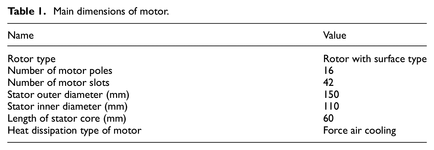
In order to verify the fast temperature rise calculation method of the motor, we use this method to calculate the temperature rise of a self-designed permanent magnet DC motor for electro-mechanical braking. The main dimensions of the motor are shown in Table 1, and the electromagnetic parameters are shown in Table 2.
Main dimensions of motor.
Electromagnetic parameters of motor.

Then, the motor model was established in Maxwell RMxprt with double winding, pitch of 2, number of conductors per slot of 56, and calculation temperature of 100°C. The winding arrangement is shown in Figure 11.
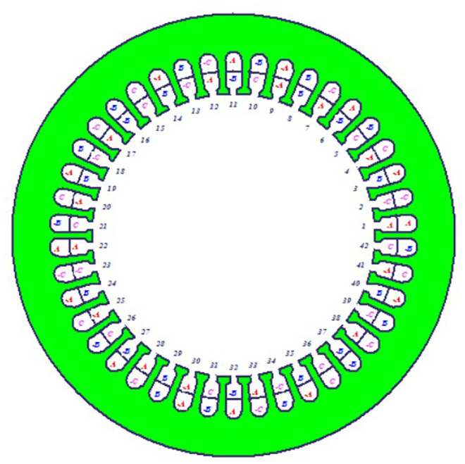
Arrangement of motor windings.
After RMxprt calculation, the motor loss under rated load is obtained as shown in Table 3.
Motor loss calculated by magnetic circuit.

In the loss parameters calculated by RMxprt, the transistor loss and diode loss are the losses in the controller, which are independent of the temperature rise of the motor body. At the same time, because the actual electric machinery brake motor is working in the state of blocking, so there is no friction wind resistance loss, iron consumption also tends to zero. Therefore, the main loss of the motor is copper loss, which is 765.1 w.
Calculation of temperature rise of motor
The motor model established in Maxwell RMxprt is simplified in axial structure, and then imported into Motor-CAD for temperature rise calculation. This simplification is because the lever and friction pair parts have little influence on the heat dissipation of the motor, so the components in the electric cylinder can be ignored: electromagnetic brakes, pressure sensors, ball screw, etc. Material properties settings for each part of the motor are shown in Table 4.
Material properties of motor.

The simulation environment in Motor-CAD is set as follows: The cooling mode was set as blow over, the wind speed was set as 20 m/s, and the ambient temperature was set as 40°C. For the motor model imported into Motor-CAD, only the copper loss of the motor is considered, and the drive mode is set to six pulses square wave drive. Boundary conditions are used in the third type of boundary conditions, input convective heat dissipation coefficient and fluid temperature. And heat load on motor winding.
Time allocation in one working cycle is shown in Figure 12. Since the clearance elimination time and braking relief time of electro-mechanical braking are very short, the process of no-load rotation is ignored, and only 30 s blocking state and 120 s motor cooling state are retained. The whole cycle time is 150 s, and the working time is 30 s, accounting for 20% of the whole cycle. When the motor works in the blocking state for 30 s, it stops working and starts air cooling at the same time.
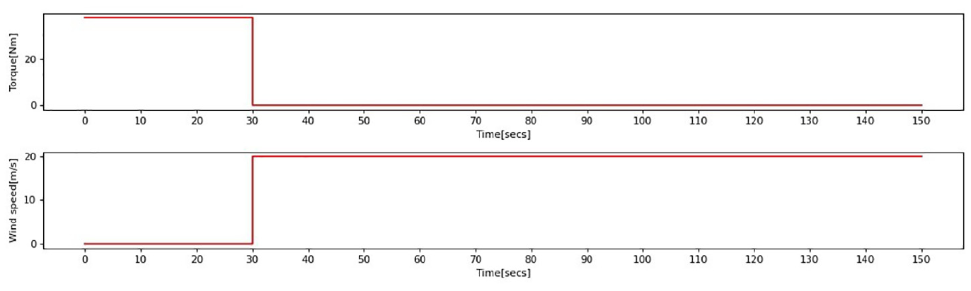
Time allocation in one working cycle.
The calculation cycle is set to 30 times to calculate the transient temperature rise. The temperature rise curve of each part of the motor is shown in Figure 13. After 30 cycles, it tends to be stable. In the figure, the curve composed of triangular symbols is the highest point of winding temperature. After 30 cycles, the temperature reaches about 112°C and the temperature rise is 72°C. However, the temperature set in RMxprt is 100°C, so iterative calculation is needed.

Calculation results by equivalent thermal circuit method.
Iterative calculation of electromagnetic loss and temperature rise
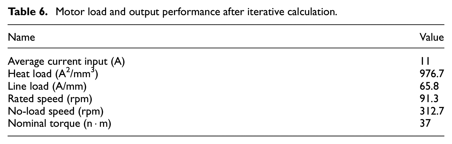
The iterative calculation results of electromagnetic loss and temperature rise are shown in Table 5. After three calculations, the maximum winding temperature is 115.1°C, and the initial set temperature is 114.7°C after iteration. The relative error between the two is only 0.3 %, reaching the convergence condition. The calculated motor load and output performance are shown in Table 6.
Iterative calculation results of electromagnetic loss and temperature rise.

Motor load and output performance after iterative calculation.
Through the electromagnetic performance and temperature rise calculation of a set of motor parameters for electro-mechanical braking in this section, the accuracy and rapidity of the fast temperature rise calculation method proposed in this paper are proved. On the other hand, it is also proved that the temperature rise of the designed motor for electro-mechanical braking can still be within the available range due to short-term operation and external air cooling under high heat load and no internal special heat dissipation.
Verification by magneto-thermal coupling finite element method
Both the equivalent magnetic circuit method and the equivalent thermal circuit method simplify the calculation of complex electromagnetic field and temperature field, and the results are the average values in a certain range. In this section, the magneto-thermal coupling finite element method28,29 is used to verify the temperature rise calculation results using the fast temperature rise calculation method.
Firstly, the Maxwell2D project is generated by RMxprt project, and the electromagnetic field global model of the motor is obtained, as shown in Figure 14.

The Maxwell2D global model.
Using external circuit as excitation which is controlled by six pulse square wave. A 2D electromagnetic field simulation results are shown in Figure 15. The average magnetic density of the stator tooth is about 1.4 t, which is not saturated. The average magnetic density of the stator yoke is about 1.5 t, which is saturated at local points.

The simulation results obtained by Maxwell2D.
Then the Maxwell2D model and the calculated electromagnetic loss are imported into Workbench and solved by transient temperature field module, as shown in Figure 16. At this time, the surface heat dissipation coefficient of the motor needs to be input. The accuracy of the thermal phenomenon analysis and temperature field calculation in the motor largely depends on the calculation accuracy of the surface heat dissipation coefficient of the motor. 30

The motor 2D model in Workbench.
The forced convection heat transfer coefficient is first calculated when calculating the surface heat transfer coefficient of the motor. For electric machinery brake motor, it is horizontally installed in the brake cylinder, its shape can be simplified as a cylinder. When the rail vehicle is running, the forced convection of the main brake cylinder can be simplified as a fluid flow around the cylinder. Forced convection heat transfer coefficient can be expressed as:

Where Nu represents Nusselt number; λ is the fluid thermal conductivity; D is the characteristic dimensions of objects. For the average Nusselt number of fluid swept single tube, the calculation formula is:

Where Re represents Reynolds number; Pr is the Prandt number. The values of C and n are selected according to Reynolds number. The Reynolds number formula is:

Where V represents the average velocity of fluid; v is the fluid viscosity.
For the existing subway train lines, the maximum operating speed is generally 80 km/h, not more than 140 km/h, that is, the speed is in the range of 22.22–38.89 m/s. The outer diameter of electro-mechanical brake cylinder is about 160 mm. It is predicted that the working temperature of the motor does not exceed 150°C, and the ambient temperature is 40°C, so the kinematic viscosity of the air is in the range of 17.6 × 10⁻⁶ to 24.34 × 10⁻⁶ m2/s. By taking these values into the equation (14) and calculating, the range of Reynolds number Re is 1.46 × 10⁵–3.535 × 10⁵. According to the Reynolds number, the constants C and n in the average Nusselt number calculation formula are 0.0266 and 0.805, respectively.
The electro-mechanical braking device is installed at the bottom of the subway train, and there are many shelters at the bottom of the train. The actual convection velocity cannot reach 80 km/h, conservative estimate is 40 km/h, namely 11.11 m/s. It is predicted that the maximum temperature of the motor winding is not more than 150°C, so the surface temperature of the electric cylinder is about 90°C. Therefore, the kinematic viscosity of air is taken as 2 × 10⁻⁶ m2/s, the Prandt number is 0.695, and the thermal conductivity is 2.83 × 10⁻² W/m/°C. Replace these values with expressions (13) and (14) to calculate Reynolds number and Nusselt number:


Bring the calculated Reynolds number and Nusselt number into equation (11), and calculate the convective conversion coefficient:

In the finite element simulation model, the motor length is 60 mm, while the actual cylinder length is 200 mm, and the heat dissipation area is larger. Therefore, in order to make the simulation conform to reality, the convective heat dissipation coefficient should be set to:

In summary, the heat dissipation coefficient of motor surface is 133.8 W/m/°C. And bring this value into Workbench, use transient temperature field module to calculate temperature rise. As shown in Figure 17, the green line indicates the maximum temperature of the motor, while the red line indicates the minimum temperature of the motor. After 10 cycles of simulation calculation, the maximum winding temperature is 113.81°C, which is only 1.3°C different from the calculation results of the rapid temperature rise calculation method. It is proved that the calculation error of the rapid temperature rise calculation method is small and the calculation results are reliable.

Simulation results of transient temperature rise of motor in workbench.
Motor temperature rise under different working conditions
Due to the different body structures and operation speed of different trains, the external heat dissipation and working cycle of the motor for electro-mechanical braking are also different, which will lead to different temperature rise of the motor. In order to master the temperature rise of electric machinery brake motor under different working conditions. We use the designed fast temperature rise calculation method to calculate the motor temperature rise under different working conditions.
Temperature rise of motor under different working cycles
Different working cycle means different motor loss duration. The larger the proportion of working time in a cycle, the larger the calorific value is, and the higher the temperature rise will be. Under the condition of ambient temperature 40°C and wind speed 20 m/s, the temperature rise of the electro-mechanical brake motor under different working cycles is simulated and calculated, and the results are shown in Table 7.
Temperature rise of motor in different working cycles.

In order to summarize the law of motor temperature rise under different working cycles, Matlab was used for function fitting of the simulation results. The fitting function used is:

Where a1 is related to motor loss and a2 is related to heat dissipation. After calculation, the value of the parameter is: a1 = 6.363, a2 = 0.7291, t0 = 36.08. The fitting curve is shown in Figure 18. It can be seen that the curve fitting error is small, and the temperature rise of the electro-mechanical brake motor in each working cycle can be accurately predicted.

Fitting curve of motor temperature rise under different working cycles.
Temperature rise of motor under different wind speeds
Different wind speeds mean different heat dissipation. The higher the wind speed is, the higher the forced convection heat dissipation coefficient of the casing and the flowing air is. Under the condition of ambient temperature 40°C and wind speed 20 m/s, the temperature rise of the electro-mechanical brake motor under different wind speeds is simulated and calculated, and the results are shown in Table 8.
Temperature rise of motor under different wind speed.

In order to summarize the law of motor temperature rise under different wind speeds, Matlab was used for function fitting of the simulation results. The fitting function adopted is:

Where a1 is related to motor loss and working cycle; a2 is related to convection area and motor structure; a3 is related to velocity index in forced convection calculation). The value of the parameter is: a1 = 177.3, a2 = 15.11, a3 = 0.3216, t0 = −25.23. The fitting curve is shown in Figure 19.

Fitting curve of motor temperature rise under different wind speeds.
The fitting curve is preciseness, which can accurately predict the temperature rise of the electro-mechanical brake motor under a certain wind speed. But in the fitting function, when the wind speed tends to infinity, the winding temperature tends to be negative infinity, which is obviously inconsistent with the theory. So this function is valid only in a certain range. At present, the operation speed of general subway is 80 km/h, and some faster subway speeds reach 160 km/h. The wind speed is not more than 50 m/s. At the same time, due to the occlusion of the bottom structure, the actual convection effect cannot reach the operating wind speed. Therefore, the effective range of the fitting curve can meet the actual train operation conditions.
Conclusions
Because of the special working mechanism of electromechanical brake motor, it is necessary to calculate its temperature rise quickly and accurately. The traditional magneto-thermal coupling calculation method of motor has low efficiency, large amount of calculation, and cannot meet the demand. Therefore, based on the coupling calculation of the equivalent magnetic circuit method and the equivalent thermal circuit method, a fast calculation method of motor temperature rise is proposed in this paper. The conclusions are as follows:
A coupling iteration method of equivalent magnetic circuit method and equivalent thermal circuit method was proposed to calculate the temperature rise of the motor. The thermal circuit model and magnetic circuit model of the motor were established in RMxprt and Moter-CAD software respectively, and the temperature rise calculation of the motor was realized through co-simulation. The results show that the temperature rise of the motor can be obtained in only three iterations, which effectively reduces the calculation amount and improves the calculation efficiency.
Maxwell and ANSYS Workbench software were used to carry out the two-dimensional finite element calculation of the magneto-thermal coupling of the motor, and obtained accurate electromagnetic field and temperature field. The calculated results of temperature field are basically consistent with those of the coupled iterative calculation of magnetic and thermal circuits. This also verifies the accuracy of the rapid calculation method of motor temperature rise proposed by us.
The temperature rise of electromechanical brake motor with different working periods and wind speeds are calculated by using this fast calculation method. Then function fitting was performed on the calculated results, and obtained numerical fitting curve. It provides a basis for the use of the motor in different working conditions and also provides a reference for the subsequent design of the motor.
Footnotes
Appendix
Acknowledgements
The authors thank the brake control research group members in Brake Technology Research Center, Institute of Rail Transit, Tongji University, for many good suggestions and discussions).
Declaration of conflicting interests
The author(s) declared no potential conflicts of interest with respect to the research, authorship, and/or publication of this article.
Funding
The author(s) disclosed receipt of the following financial support for the research, authorship, and/or publication of this article: This research was funded by the National Nature Science Foundation of China (Grant No.52072266)