
Abstract
The dynamic characteristics of electric drive systems are crucial in electric vehicles. Based on the dynamic finite element method and previous studies, this study proposes and analyzes a new mathematical model for a motor longitudinally mounted on a centralized electric drive system of a pure electric vehicle. First, we analyze the largest torque ripple of a fractional slot concentrated winding inner-mounted permanent magnet synchronous motor designed for commercial electric vehicles. This torque ripple is identified as one of the excitations influencing the dynamic performance of the electric drive system. Second, a new dynamic mathematical model for the electric drive system is established. Third, we investigate the linear vibration responses of the system subject to torque ripple and transmission error. Finally, the relationships between critical motor parameters and dynamic mesh force are revealed. The results demonstrate that the proposed theoretical method can effectively determine the dynamic characteristics of the electric drive system, thereby providing valuable theoretical guidance for the design and optimization of the motor and electric drive system.
Keywords
Introduction
The dynamic performance of electric vehicles is crucial for evaluating their driving quality. The effective suppression of unwanted vibrations contributes significantly to overall quality improvement. The engine is the primary source of vibrations in traditional vehicles powered by internal combustion engines. However, the absence of an engine in pure electric vehicles accentuates the vibrations from the electric drive system. Therefore, accurately characterizing the dynamic performance of electric drive systems is crucial. 1 Extensive research has been conducted on the vibration associated with electric drive systems. Many studies have focused on finite element methods or experimental methods, utilizing finite element software or constructing experimental platforms to investigate the dynamics of electric drive systems. Xu et al. 2 used finite element and modal synthesis methods to analyze the drive axle gear transmission dynamic system considering the effects of housing. Huang et al. 3 constructed an experimental platform to analyze the impact of different motor torque limits and transmission systems on the dynamic performance of distributed electric drive systems and electric vehicles to identify the primary factors influencing the dynamic performance of electric vehicles. Chen 4 utilized the professional software Hypermesh and LS DYNA to simulate the vibrations caused by the electric powertrain in an electric bus during rapid acceleration/deceleration and gear-shifting scenarios. Zuo et al. 5 established a longitudinal-torsional coupled dynamic model of an in-wheel-motor-driven electric drive system using finite element methods. Zhao et al. 6 developed a virtual prototype for in-wheel-motor-driven electric vehicles by combining CATIA, ADAMS, and MATLAB/SIMULINK environments. This high-fidelity multibody model was then used to validate the functionality of an integrated vibration elimination system proposed by the authors.
However, some studies prefer to use simplified mathematical models. Hassan et al. 7 introduced a mathematical dynamic model and analyzed the effect of different motor control methods on the dynamic performance of the vehicle. Yu et al. 8 established a nonlinear mathematical model of an electric vehicle driven by an in-wheel motor and investigated the influence of different suspension settings on the dynamic behaviors of the whole vehicle. Tang et al. 9 developed a novel simplified mathematical model to investigate the torsional vibration of parallel planetary transmission systems for hybrid electric vehicles, and the results indicated that the proposed model could accurately describe the low-frequency vibration of the hybrid powertrain. Shi et al. 10 introduced a mathematical multi-degrees-of-freedom (DOF) vertical vibration model and designed a multistage passive vibration-isolating system and an active motor vibration-absorbing system for an electric vehicle driven by a wheel-hub motor. Mao et al. 11 developed a mathematical model of a quarter vehicle-electric wheel system and investigated the high-frequency vibration of an in-wheel-motor-driven system under the excitation of torque ripple. Yi et al. 12 developed a mathematical torsional model using the lumped parameter method for a multistage gear set consisting of fixed-shaft and planetary gears. Bai et al. 13 employed a tooth contact analysis method to construct a mathematical electromechanical dynamic model of an electric drive system. Hou et al. 14 proposed a hybrid finite element-analytical method and established a rigid-flexible coupled dynamic model of electric drive systems considering shaft elasticity, bearing stiffness, and housing flexibility. Ge et al. 15 established an electromechanical coupling mathematical dynamics model of the dual-motor electric drive system, including the permanent magnet synchronous motor and the gear transmission system. Duan et al. 16 conducted a system-level transmission error investigation of the gearbox by proposing a rigid-flexible coupling dynamic mathematical model. In this model, the meshing pair, flexible shaft, and bearing were established by a lumped mass element, beam element, and spring element, respectively.
The motor serves as a power source and a significant contributor to the dynamic characteristics of the electric drive system. Consequently, numerous studies have attempted to optimize the motor to enhance the dynamic performance of the electric drive system. Wang et al. 17 compared IPM motors comprehensively, evaluating three design approaches aimed at reducing cogging torque, torque ripple, and electromagnetic vibration. Zhao et al. 18 proposed a comprehensive approach for studying the vibration characteristics of an electrical machine stator used in an electric vehicle with an encased construction under practical boundary conditions. Raj et al. 19 utilized a finite element software package, “Motorsolve”, and MATLAB/SIMULINK environment to design a three-phase 12/8 switch reluctance motor specifically tailored for electric vehicles. Deng et al. 20 proposed an independent current chopping control strategy for in-wheel motors to achieve optimum control between the response characteristic of the in-wheel motor driving system and the dynamic performance of electric vehicles. Chen et al. 21 investigated the coupling relationship between torque fluctuations and harmonic currents by developing an analytical model for the instantaneous torque of a permanent magnet synchronous motor (PMSM). The aim was to address the torque fluctuations in PMSMs caused by flux harmonics.
Few studies focused on the dynamic behaviors of specific components, such as gears, shafts, and bearings. However, their dynamic behavior is crucial and can influence the overall dynamics of the electric drive system. Cao et al. 22 developed an enhanced dynamic model of a motor-gear system. The model incorporated the effects of both motor and load excitations, enabling an analysis of the changing processes of tangential, axial, and torsional vibration variables in the driving gear and driven gear using the state space method. Guo et al. 23 developed a refined dynamic model for a single pair of gears to predict the gear rattle accurately. Ning et al. 24 employed a novel method that converts vehicle speed into a load, enabling the determination of the load spectrum for the reducer gears based on real road driving cycles. Kang et al. 25 proposed a systematic methodology for designing speed-reduction gears, aiming to analyze their impact on the performance of input-split and output-split hybrid electric vehicles. Chen et al. 26 established a novel dynamic model of planetary gear transmission using Newton's theory. This model incorporated key factors such as time-variant meshing stiffness, phase relationships, and tooth contact characteristics. Sheng et al. 27 focused on gear faults in an electric drive system. They established a gear failure model and a system torsion dynamics model to investigate the impact of various faults on the electromechanical performance of the system. Inalpolat et al. 28 employed a dynamic model of a spur gear pair to investigate the influence of gear tooth indexing errors on the dynamic response. The model predicted frequency-domain dynamic mesh force and dynamic transmission error spectra using quasi-static transmission error time traces as the primary excitation.
Although there has been extensive research on electric drive systems, there are still some limitations and shortcomings. First, the mathematical models in previous studies have been overly simplified, compromising their accuracies, whereas constructing finite element models requires considerable time. Second, although electric commercial vehicles represent the future of commercial vehicles, only some studies have focused on them. Third, there is a lack of in-depth research on the gears and bearings of electric drive systems. To address these limitations, this study establishes a high-accuracy 92 DOF mathematical model for a motor longitudinally mounted centralized electric drive system (Figure 1). This is widely used in electric commercial vehicles for its convenience in construction, relatively lower manufacturing cost, precision and stability in transmission, enhanced load-carrying capability and superior noise, vibration and harshness (NVH) performance.29,30 The model is constructed based on a validated method, focusing on analyzing the dynamic characteristics of gears and bearings in an electric drive system and investigating the impact of the motor on the gear dynamics. The specific research and methodologies are outlined in detail below.

Motor longitudinally mounted centralized electric drive system.
First, a new 92-DOF model was constructed for a motor longitudinally mounted on a centralized electric drive system. This model was inspired by a dynamic finite element modeling method for a spiral bevel gear transmission system of a rear-wheel-drive internal combustion engine-powered vehicle introduced by Hua et al.31,32 and verified by Cheng. 33 The torque ripple of a fractional slot concentrated winding PMSM (FSCW-PMSM) was then investigated, and the results were compared to other findings to demonstrate the accuracy. Second, we investigated the dynamic mesh force, dynamic bearing force and displacement or torsional displacement of motor, pinion shaft and gear shaft under torque ripple, and transmission error excitations. Finally, relationships between the dynamic mesh force and four critical motor parameters were investigated.
Methods
Torque ripple analysis of FSCW-IPMSM
The FSCW-PMSM has been the primary choice for electric vehicles due to its advantages of rapid response, high performance and high efficiency.34,35 Among them, fractional slot concentrated winding inner-mounted PMSM (FSCW-IPMSM) is more commonly used in electric vehicles due to its superior performance. Therefore, we selected a 16-poles, 24-slots FSCW-IPMSM in this study. The main specifications of this FSCW-IPMSM are listed in Table 1, and a cross-sectional view is illustrated in Figure 2.

Cross-sectional view of the FSCW-IPMSM. FSCW-IPMSM: fractional slot concentrated winding inner-mounted permanent magnet synchronous motor.
Main Specifications of the FSCW-IPMSM.

FSCW-IPMSM: fractional slot concentrated winding inner-mounted permanent magnet synchronous motor.
The torque ripple of FSCW-IPMSM can be expressed as follows
36
:


Referring back to equation (1), 
The spectrogram of the torque ripple under the rated working condition is illustrated in Figure 3.

Spectrogram of torque ripple.
The result shows that the maximum torque ripple is approximately 7.52Nm. Torque ripple ratio 
This study summarized several reliable conclusions from the other studies to validate the accuracy of the torque ripple rate. He et al. 37 compared and optimized the torque ripple of FSCW-PMSMs for electric vehicles with different rotor topologies. For FSCW-IPMSM, the largest torque ripple ratio was 5.16% before optimization. Chung et al. 38 analyzed an FSCW-PMSM with a modified consequent pole rotor, and the maximum torque ripple ratio was 5.7%. Dutta et al. 39 investigated and compared three FSCW-PMSMs with different rotor topologies, they considered that regardless of the type of topologies, maximum torque ripple ratio should be lower than 5%. Jedryczka et al. 40 demonstrated that the largest torque ripple ratio of an FSCW-PMSM was 1.02%. Thus, studies showed that the average torque ripple ratio of different FSCW-PMSMs should range from 1% to 10%. Therefore, 4.7% was a reasonable result, indicating that equation (1) could accurately calculate the torque ripple of an FSCW-IPMSM. Therefore, the torque ripple excitation was set to 7.52 Nm in this study.
Construction of 92-DOF mathematical model for motor longitudinally mounted centralized electric drive system
The schematic model of the proposed motor longitudinally mounted centralized electric drive system is illustrated in Figure 4(a). The system incorporates two tapered roller bearings (bearing 1 and bearing 2) and a deep groove bearing (bearing 3) to support the pinion shaft. In contrast, the two additional tapered roller bearings (bearing 4 and bearing 5) are employed to support the gear shaft. Torsional springs are used to connect the FSCW-IPMSM with the pinion shaft and the gear shaft with the load. The torque ripple generated by the FSCW-IPMSM and the transmission error caused by the meshing pair are the two excitations that contribute to the vibration of the electric drive system.

(a) Schematic model and (b) Dynamic finite element model.
Figure 4(b) shows the 92-DOF mathematical model for the proposed motor longitudinally mounted centralized electric drive system. Specifically, node 1 represents FSCW-IPMSM with a single DOF, which only contains the torsional moment of inertia. Similarly, the external load is represented as a rotating element, and node 17 also has only a single DOF. The mass matrix for the motor and load can be expressed as follows:


Node 10 represents differential assembly. It contains 6 DOFs and thus can be formed by a 
The torsional spring connecting the motor and the pinion shaft can be represented by spring and damping elements between nodes 1 and 2. Similarly, another torsional spring is used to connect the gear shaft and the load, which can also be represented by spring and damping elements between nodes 16 and 17. Since nodes 2 and 16 both have 6 DOFs while nodes 1 and 17 only have a single DOF, the stiffness matrix 
The system mass matrix 

Subsequently, the total damping matrix 
The excitation can be represented by a vector 


where 
The overall differential equation can then be expressed as follows:

Results and discussions
Overview
This section investigates and compares some key dynamic characteristics of the system, namely the dynamic mesh force, dynamic bearing force, and displacements of the PMSM, pinion shaft, and gear shaft. The dynamic mesh force, which acts on the teeth of the pinion and gear, reveals the torsional resonance of the meshing pair and its impact on the electric drive system. Bearings support and bear torques between the motor and the load. Therefore, the dynamic behavior of bearings directly influences the system's vibration responses. The displacements of components can reflect the displacement characteristics of the entire electric drive system under vibration.
Analysis of dynamic mesh force
In this section, the dynamic mesh forces under two excitations are analyzed. The calculation method of dynamic mesh force 
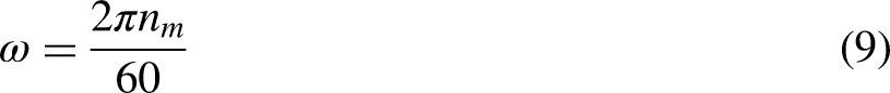
Comparison of dynamic mesh force excited by torque ripple and transmission error.
Figure 5 shows the overall trend of the two lines: when the system is excited by torque ripple, the dynamic mesh force first fluctuates violently in the low motor speed range, then rapidly increases with the motor speed, and finally stabilizes around a high constant value. When the excitation is a transmission error, a curve with the opposite trend can be observed. As the motor speed increases, the dynamic mesh force decreases rapidly and finally stabilizes around a low constant value. Specifically, when the motor speed is below 550 rpm, the two curves are coupled together and the maximum dynamic mesh force caused by torque ripple and transmission error is 620 and 769 N, respectively. This phenomenon indicates that at motor speeds below 550 rpm, both torque ripple and transmission error contribute almost equally to the dynamic mesh force. When the speed exceeds 550 rpm, the two curves begin to decouple, and their discrepancy increases. When the motor speed exceeds 4000 rpm, the curves begin to stabilize. At this stage, the maximum dynamic mesh force caused by transmission error is 20472 N, occurring at 4185 rpm, while the maximum dynamic mesh force caused by torque ripple is only 0.5 N, occurring at 4430 rpm. This phenomenon indicates that transmission error is the primary factor contributing to the dynamic mesh force during high-speed conditions, and the contribution of torque ripple can be neglected. In conclusion, when the motor operates at low speeds below 550 rpm, transmission error and torque ripple contribute almost the same to the dynamic mesh force. Transmission error gradually becomes the main cause of the dynamic mesh force as the motor speed increases. The dynamic mesh force caused by torque ripple can be neglected when the motor speed exceeds 4000 rpm.
Analysis of bearing transverse forces
Since the bearings used in this study are tapered roller bearings, which primarily bear radial loads, the radial loads of bearings can be represented by transverse forces. Therefore, the transverse forces of four tapered roller bearings are analyzed in this section. The displacements representing bearings 

The simulation results are shown in Figure 6.

The transverse force of (a) bearing 1, (b) bearing 2, (c) bearing 3, and (d) bearing 4.
Figure 6 shows that the overall trend of bearing transverse force versus the motor speed is similar to that of dynamic mesh force. When motor speed is slow, the amplitude of bearing transverse force fluctuates violently within a similar y-axis range under both excitations. Subsequently, the amplitude under the transmission error excitation increases rapidly as motor speed increases, whereas the amplitude excited by torque ripple decreases. Specifically, when the motor speed is below 515 rpm, the two curves are coupled together, and the maximum amplitudes under the torque ripple excitation of the four bearings are 373, 99, 814, and 274 N, respectively. Similarly, the maximum amplitude under the transmission error excitation of the 4 bearings is 462, 123, 1008, and 339 N, respectively. The difference between the bearing forces caused by torque ripple and transmission error is minimal, indicating that they are both the main contributors to the bearing forces. As the motor speed exceeds 515 rpm, the 2 curves decouple and the difference between them increases. For example, when the motor runs above 3000 rpm, the maximum amplitudes of the 4 curves caused by transmission error are 21125, 7012, 30637, and 16374 N, respectively, while the maximum amplitudes caused by torque ripple are only 0.28, 0.076, 7.40, and 4.80 N, respectively. From these observations, we can conclude that when the motor speed is below 515 rpm, the dynamic bearing forces are jointly influenced by the dynamic mesh forces and torque ripple. In contrast, at motor speeds above 515 rpm, the contribution of torque ripple can be neglected.
Analysis of displacements
In this section, the displacement of the PMSM, pinion shaft, and gear shaft are analyzed. Those displacements can be extracted from

(a) Torsional displacement of motor, (b) displacement of pinion shaft, (c) displacement of gear shaft, (d) torsional displacement of pinion shaft, and (e) torsional displacement of gear shaft.
The phenomenon observed in Figure 7 is similar to those of previous figures. Specifically, when motor speed is lower than 515 rpm, the largest amplitude of Figure 7(a) to (e) caused by torque ripple are
We can obtain the same conclusion from the results of Figures 5 to 7. The motor speed of 515 rpm is a critical point of the system. When the motor speed is below 515 rpm, both torque ripple and transmission error cause the dynamic responses of the system. However, when the motor speed exceeds 515 rpm, the dynamic responses of the system are primarily caused by transmission error excitation. When the motor runs above 3000 rpm, the influence of torque ripple on the system's dynamic response is significantly smaller than the effect of transmission error and can be neglected. This conclusion reveals the dynamic characteristics of the proposed electric drive system and provides a theoretical basis for its design and optimization. Specifically, when the electric drive system operates at low speeds, both torque ripple and transmission error should be considered significant optimization objectives since they contribute equally to the system's dynamic response. As the electric drive system enters high-speed operation conditions, priority should be given to optimizing transmission error, because the influence of torque ripple becomes negligible.
Notably, we only studied the dynamic characteristics when the motor runs below 10,000 rpm. This is because centralized electric drive systems are primarily used in electric commercial vehicles, and the motors generally operate below 10,000 rpm.
Analysis of relationships between motor parameters and dynamic mesh force
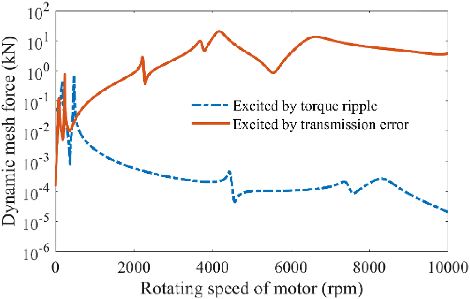
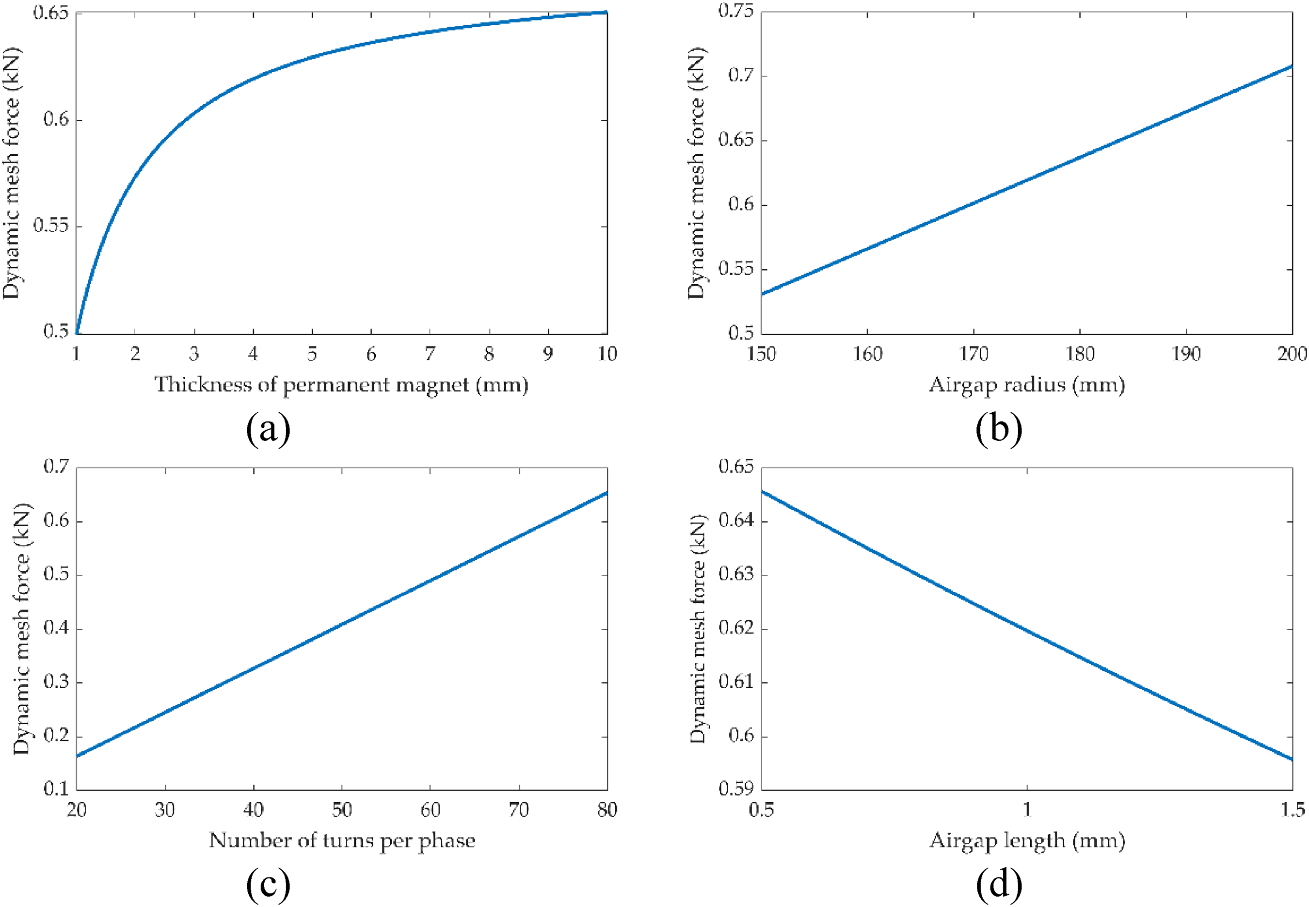
Figure 8 illustrates the relationships between four critical motor parameters and dynamic mesh force. The four parameters are airgap length, airgap radius, number of series turns per phase, and thickness of the permanent magnet. Airgap length is defined as the gap between the stator and rotor. The airgap radius is the sum of the rotor radius and half of the airgap length. The number of series turns per phase is the total turns of coils in each phase. These four parameters are illustrated in Figure 9. Figure 9(c) only presents coils in one stator tooth for convenience.
Relationship between (a) thickness of permanent magnet, (b) airgap radius, (c) number of turns per phase, and (d) airgap length and dynamic mesh force.
Geometric schematic diagram of (a) airgap length, (b) airgap radius, (c) number of series turns in one stator tooth, and (d) thickness of the permanent magnet.
Figure 8(a) to (c) show that the magnitudes of dynamic mesh force increase as motor parameters increase. In Figure 8(d), the magnitude of dynamic mesh force decreases when the airgap length increases. This phenomenon reveals a simple relationship between key motor parameters and dynamic mesh forces. Specifically, the dynamic mesh forces also increase as the thickness of the permanent magnets, air gap radius, and number of series turns per phase increase. However, when the air gap length increases, the dynamic mesh forces decrease. This indicates that for the proposed electric drive system, smaller values for the permanent magnet thickness, air gap radius, and number of series turns per phase are preferable, while a larger air gap radius is desirable. However, these motor parameters should be selected based on the motor's performance guarantee. Based on motor engineering knowledge, minimal values for permanent magnet thickness, air gap radius, and number of series turns per phase can severely limit the motor's performance, which in turn affects the performance of the electric drive system. Therefore, the results shown in Figure 8 provide theoretical guidance for selecting motor parameters, emphasizing the importance of selecting appropriate values to ensure that the motor's performance is not significantly compromised while controlling the system response within a reasonable range.
Comparison to previous research
In this section, a comparison of dynamic mesh force is made between this study and an existing model.31,33 The existing model is a 14-DOF lumped parameter model for a centralized drive system, which has the same structure as the drive system presented in this study. Specifically, the engine and load have one DOF in the torsional direction, whereas pinion and gear are represented by rigid bodies with six DOFs. The gear meshing is represented by mesh stiffness, mesh damping, and static transmission error. The pinion shaft that connects the pinion and engine and the gear shaft that connects the gear and load are represented by torsional springs. The bearings that support the pinion shaft and gear shaft are also represented by torsional springs connected to the lumped points of the pinion and gear. The governing equation of motion can be expressed as follows:


Figure 10 shows that the two curves show good agreement for frequencies below 742 Hz, while slight differences are observed for frequencies above 742 Hz. In other words, some of the natural frequencies predicted by the 14-DOF and the 92-DOF models are inconsistent. The most notable discrepancies are observed in mode a (742 Hz), mode b (832 Hz), and mode c (1309 Hz) of the 92-DOF model. The reasons for these discrepancies are analyzed as follows: firstly, the 14-DOF model simplifies the modeling of shafts and bearings by replacing them with spring elements connected to the center of mass of the gears to the ground. This approximation has some impact on the accuracy of the model. However, the 92-DOF model developed in this study incorporates precise modeling of all components of the drive system, which theoretically allows for accurate prediction of the system's dynamic behavior. To demonstrate this conclusion, we investigated the modal shapes of the 92-DOF model at mode a (742 Hz), mode b (832 Hz), and mode c (1309 Hz) as shown in Figure 11. The results indicate that coordinate numbers 4, 10, 22, 28, 34, and 40, which correspond to torsional vibrations of the shaft and bearings, contribute significantly to the modal shapes. In other words, the 92-DOF model demonstrates a higher accuracy in predicting the torsional vibrations of the shafts and bearings compared to the 14-DOF model, which causes the discrepancies of two lines in Figure 10. In conclusion, the comparison with the existing 14-DOF model reveals that the 92-DOF and the 14-DOF models yield similar results, with only slight differences observed at high frequencies. However, since the 92-DOF model has a higher modeling accuracy, there is reason to believe that the 92-DOF model developed in this study can accurately predict the dynamic behavior of the proposed electric drive system.

Comparison of dynamic mesh force to a 14-DOF lumped parameter model under the excitations of transmission error. DOF: degrees-of-freedom.

Mode shapes of (a) mode a, (b) mode b, and (c) mode c of the 92-DOF model. DOF: degrees-of-freedom.
Conclusion
In this study, the dynamic characteristics of the proposed motor longitudinally mounted on a centralized electric drive system were investigated using a new 92-DOF lumped parameter model. The simulation results showed that when the motor speed was lower than 515 rpm, the system responses were caused by torque ripple and transmission error together. However, when the motor speed was higher than 515 rpm, the system responses were mainly caused by transmission error. The relationships between motor parameters and dynamic mesh force showed that as the thickness of the permanent magnets, air gap radius, and number of series turns per phase increased, the dynamic mesh forces also increased. However, when the air gap length increased, the dynamic mesh forces decreased. Finally, we compared our findings with an existing 14-DOF lumped parameter model. The result indicated a general agreement between the 2 models, demonstrating the accuracy of the 92-DOF model established in this study. To summarize, the simulation results provided a theoretical foundation for designing and optimizing a motor longitudinally mounted centralized electric drive system. However, the proposed method in this study still has the following limitations: First, this study simplified the modeling of the motor, resulting in a less accurate analysis of torque ripple. Second, the load was also simplified to a node with only one torsional DOF. Third, although the simulation results were compared to the existing research, there was a lack of in-depth validation analysis. To address these limitations, future works could concentrate on the following enhancements: detailed modeling of the motor and load to achieve higher precisions and conducting more comprehensive validation analysis using professional finite element software and experimental methods.
Footnotes
Abbreviations
Declaration of conflicting interests
The authors declared no potential conflicts of interest with respect to the research, authorship, and/or publication of this article.
Funding
The authors disclosed receipt of the following financial support for the research, authorship, and/or publication of this article: This work was supported by the National Natural Science Foundation of China, Natural Science Foundation of Zhejiang Province (grant number 52005443, LQ21E050016).
Author biographies
Appendix
System Parameters.

| Gear parameters | Pinion | Gear |
|---|---|---|
| Number of teeth | 14 | 45 |
| Mass (kg) | 12.6 | 34.2 |
| Torsional moment of inertia (kg.m2) | Ipx = 0.05 Ipy = 0.02 Ipz = 0.02 |
Igx = 1.01 Igy = 0.9 Igz = 0.9 |
|
|
Pinion shaft | Gear shaft |
| Outer diameter (mm) | 90 | 120 |
| Inner-diameter (mm) | 0 | 0 |
| Young's modulus (Gpa) | 207 | 207 |
| Poisson's ratio | 0.3 | 0.3 |
|
|
||
| Stiffness matrix of bearing 1 |
|
|
| Stiffness matrix of bearing 2 | ||
| Stiffness matrix of bearing 3 | ||
| Stiffness matrix of bearing 4 | ||
| Stiffness matrix of bearing 5 | ||
|
|
PMSM | Load |
| Torsional moment of inertia (kg.m2) | 2.6 | 5.2 |
|
|
||
| Mass (kg) | 81.9 Idx = 0.9 Idy = 0.8 Idz = 0.8 |
|
| Torsional moment of inertia (kg.m2) |
||
|
|
||
| Mesh stiffness |
|
|
|
|
||
| Mesh damping ratio | 0.06 | |
| System damping ratio | 0.02 | |
PMSM: permanent magnet synchronous motor.