
Abstract
Recently, high tensile fibres composite laminates (i.e. glass composite laminates) have been widely used in the civil and military applications due to their superior properties such as lightweight, fatigue and corrosion resistance compared to metals. Nevertheless, their brittle fracture behaviour is a real downside for many sectors. In the present study, the impact of the hybridisation of Kevlar woven layers with glass woven layers on the reducing the strain failure problem in pure glass woven laminates is investigated. In this work, multi-layers Kevlar-glass with different stacking sequences have been used to prepare the hybrid composite laminates using vacuum–assisted resin moulding method. The influence of the layers hybridisation on the mechanical performance of composites laminates was investigated using tensile strength tests. Furthermore, finite element analysis is performed to analyse the mechanical response of the hybrid composite laminates using Abaqus software. The elastic constants of woven fabric layers in the numerical study were predicted through geometric model based on the textile geometry and analytical method in order to assert accuracy of the predicted elastic constants. The experimental results showed that the hybrid composite laminates tend to fail more slowly than glass woven laminates, which illustrates low strain to failure. In the theoretical part of the study, it was found that the proposal model can be useful to capture the mechanical behaviour and the damage failure modes of hybrid laminates. Thus, the catastrophic failure can be avoided in these laminates.
Introduction
Despite the popularity of the glass fibre reinforced polymer composites (GFRP ) use in aircraft and aerospace engineering industries, for a long time due to their high specific strength-to weight ratio, non-corrosive properties and have a very low strain-to-failure.1–4 Accordingly, this is considered as a disadvantage for using these laminates under a tensile or/flexural loading conditions. 5 Additionally, in civil infrastructures, structural stability is a key factor that maintains a structure to be safe in usage under static or dynamic loading conditions. 6 Kevlar has excellent mechanical properties such as high strength with lightweight, thermal stability and good resistances to abrasion resulting in wide use in aerospace, military applications, protective apparel and marine industry.3,7,8 However, the major limitation for using them in the different sectors are their weaknesses in tensile, compression and bending loading. 9 One possible way to achieve better performance is by adopting a hybrid composite that is made up of two or more different fibres or resins. Hybridisation of fibres can be combined the high modulus fibres, which has capability for carrying load with the low modulus fibres.10,11 Thus, hybridisation will provide advanced performance (i.e. improves damage tolerance, impact resistance and reduces the material cost than that obtained from an individual reinforcement.4,12,13 Based on the numbers and distribution of fibres in a hybrid composite, they can be categorised into, interlaminated hybrids where different layers are stacked together, intra-ply or intra-yarn hybrids, where many yarns or bundles are mixed together in one layer and intermingled hybrids, where the consistent fibres are mixed as randomly as possible in the composite laminates.14–16 Many researchers have successfully used intra-ply hybridisation technique to enhance the mechanical properties of composite laminates.17–20 This can be attributed to enhancement of the first failure strain of the low-elongation fibres by incorporating more ductile fibres and that can improve the specific ultimate properties of composites. 21 Besides that, hybrid layers (inter-ply layers) of composite laminates can strongly influence on their mechanical properties, 22 and impact loading resistance and damage tolerance.23–25 Recently, researchers have paid attention for using numerical analysis and simulation of mechanical behaviour of composite laminates. 26 The main target is to show the advantage of the additionaly woven layers such as basalt,27–29 carbon,5,30–32 and kevlar woven layers20,33 with glass woven layers in case of hybrid composite laminates compartively with composite lamintes reinforced only with glass woven layers.The complex geometry of woven fabrics imposed many challenges in the numerical analysis of woven fabrics composites. 34 Thus, development of efficent methods for prediction elastic constants of woven fabrics composite is esstential.35–41 The prediction models for elastic constants of woven composites classified into two types; numerical model based on the finite element method39,42–44 and analytical models. 45 The numerical model based on the finite element offered higher accuracy because of less simplifying assumptions and consideration of more details, however the implementation of these models is expensive and consumed more time compared to the analytical models.40,46 In the other hand, the analytical models for prediction of woven fabric composites are usually depend on the multi-scale modelling, which known as the top-down-bottom-up methods. 47
The main novelty of this study is the investigation of tensile response of glass/ Kevlar layers composite laminates considering the hybridisation effect. These laminates were manufactured using vacuum bagging process and tensile strength characteristics of hybrid laminates were experimentally measured. In addition, the simulation of tensile performance of hybrid laminate was done using FEA with aiding of Abaqus software and compared with experimental results. The elastic constants of composite lamina, which were used in the numerical model, have been predicted through the geometrical model based on the fibre architecture and analytical methods.
Materials and experimental tests
Materials
Glass and Kevlar fabrics are used in this study and they are illustrated in Figure 1. The specifications of these fabrics are showed in the Table 1. The fabric count (i.e. the number of warp and weft in 1 cm), areal density and thickness are measured according to ASTM standards, which are D3775-02, D3776-09 and D1777-09, respectively.
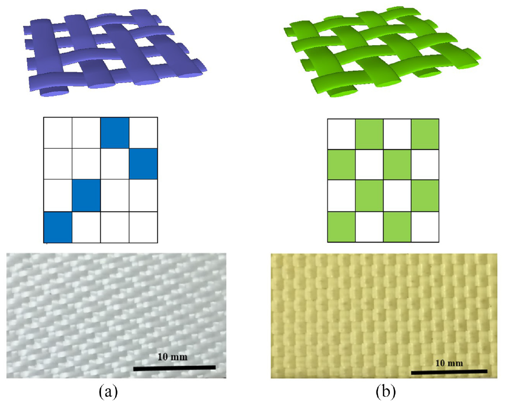
Glass fabric (a) and Kevlar fabric (b).
Specifications of glass and Kevlar fabrics.

Composite laminate manufacturing
The low viscosity resin (Sikadur-52) and its hardener with mixing ratio (1:2) were used to create the matrix in the composite laminate. The composite laminates were made by infusing epoxy resin with aiding a vacuum bagging technique in which four layers of fabrics with a stacking of [0, 90] degrees were laid over one another to manufacture glass fabric and Kevlar fabric composite laminates as seen in Figure 2(a) and (d). While two types of the hybrid composite laminates were produced; the former was done by laid Kevlar fabrics on the top and bottom and glass fabrics on core of composite laminates (Figure 2(b)), the later made by laid glass fabrics on the top and the bottom and Kevlar fabrics on the core (Figure 2(c))
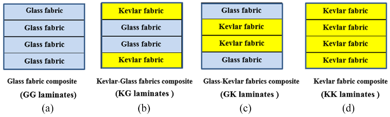
Composite laminates configurations.
Preparation of resin and infusion
Sikadur-52 resin and its hardener were used to create the matrix in the composite laminate preparation. After mixing with a ratio of 1:2 and stirring for 10 min, the mixture was put in a degassing machine for a period of 1 h to ensure the complete removal of gas bubbles to make a void free panel. The resin was introduced into the bag through the PVC feed pipe by connecting a vacuum pump to the exit pipe. The ingress of resin was kept slow enough to ensure adequate wetting of the preform. After the resin reached the end of the panel, the vacuum pump was turned off and the PVC pipes were sealed using clamps. The last stage of manufacture of the composite included the curing of the panel in room temperature for 24 h. When the curing cycle was complete, the panel was taken out and de-moulded, then machined with handsaw to obtain samples with the required dimensions.
Experimental methods
Density and fibre volume fraction tests
The density of composite laminates are measured according to the ASTM D792-08 standard. The volume fraction of these composite laminates are measured in both experimental and theoretical methods, respectively. For example, the volume fraction of the glass only and Kevlar only composites are measured experimentally according to the BS EN ISO 1172:1999 standards, meanwhile the volume fraction of hybrids layers composites are calculated theoretically as shown in equation (1) because of the difficulty of burning method with hybrid layers.
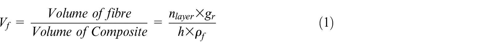
Where,
Average properties of composite laminates.

Tensile properties tests
The tensile properties of all composite samples were also evaluated using a tensile strength test. The specimens were cut from the laminates with a diamond cutter; samples measured 250 mm x 25 mm (length x width) and had a gauge length of 50 mm, in accordance with the ASTM D3039M 2008 standard. 48 Five specimens were created for each case. End tabs were affixed to the specimens in order to reduce the gripping effects. Tensile tests were conducted using an Instron 5982 universal testing machine at a crosshead rate of 2 mm/min, corresponding to a strain rate of 0.2%/s. Tensile test machine and sample of test have been illustrated in Figure 3.
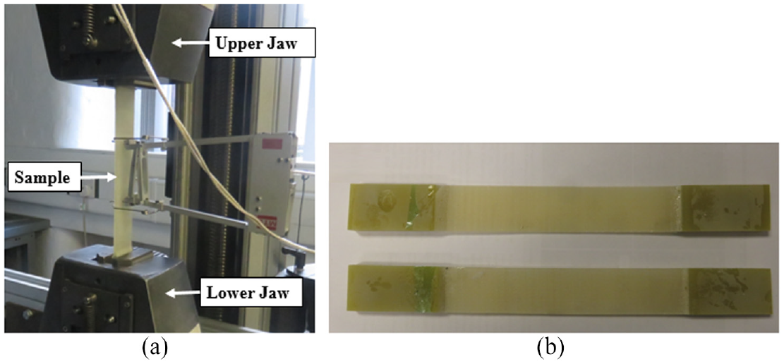
Tensile test machine (a) and composite sample of test (b).
Numerical analysis
Finite element model description
The mechanical performance of hybrid composite laminates, which are experimentally investigated, can be represented and assessed by using numerical analysis since it is relatively accurate, less cost and less time-consuming. For this aim, a finite element method using commercial software package Abaqus/ Explicit has been adopted to simulate the response of hybrid composite laminates under tensile strength test.
The hybrid composites being investigated in this study are manufactured from two types of fabrics, Satin E-glass and Kevlar plain into a common matrix epoxy. The elastic constants of lamina of these hybrid composites, which are including the longitudinal modulus
Formulation of geometric model
The simulation of mechanical properties of composite laminates are mainly focused on the stiffness of each lamina and these properties must be calculated either numerically or analytically. Additionally, the stiffness of the lamina and laminates depended significantly upon various factors (i.e. basic mechanical properties of the matrix and fibre, amount or volume fraction of matrix and fibre and type and orientation of reinforcement).
In this regard, an analytical strategy has been proposed to predict elastic properties of lamina of woven composite. Emphasis is on elastic model and on the parametric study of the effects of fibre volume fraction, local fabric geometry, weave type and material properties. In the geometry model, overlap between neighbouring yarns is accounted; orientation and crimp angle of sub-volume of yarns is predicted based on experimental measured fabric local geometries.
In this model, elastic properties of the yarn are predicted based on a linear rule of mixture. Then a two level homogenisation approach is applied to predict engineering constants of woven composite based on constituent material properties: at micro-level or yarn level, transformation matrix is applied to calculate the stiffness matrix of warp and fill yarn in global system. At macro-level or unit cell level, homogenisation based on iso-strain and iso-stress assumptions is carried out to predict the elastic properties of unit cell.
Formulation of geometric model for woven composite lamina starts with defining the yarn shape in the fabric and neighbouring yarn configuration. The parameters determined in yarn shape and neighbouring yarn. The cross-section of a yarn in the woven lamina composite is assumed lenticular shape. This assumption is realistic as a fill yarn is interlocked and compressed by over-and under-laid warp yarns as depicted in Figure 4,
49
where a cross-section factor


For the case of warp yarn, the subscript f is changed with w in above equations. Conventionally, it is assumed that there is a gap between neighbouring yarns and yarn-to-yarn distance can be calculated based on this assumption. When the gap is large, a straight portion of yarns can exist. This configuration is shown in Figure 5.
49
The gap between neighbouring yarns is shown as

Definition of yarn shape and geometry parameters. 49
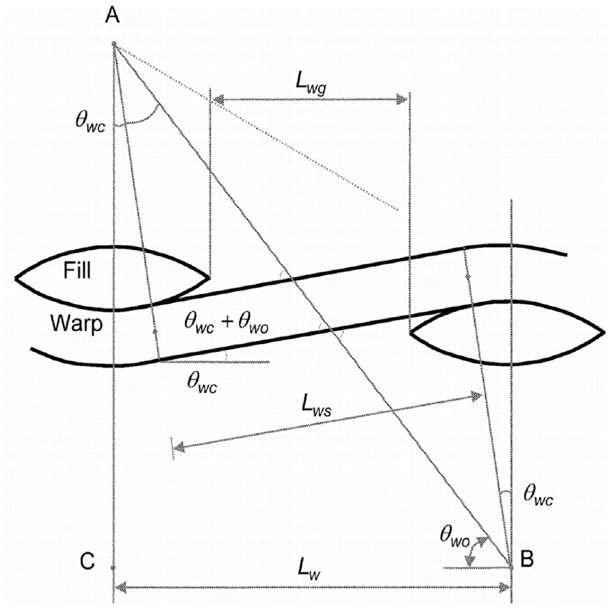
Geometric model of woven fabric when there is a straight portion of yarn. 49
In this configuration, the yarn to yarn distance,

Where


For warp yarn sections, the similar forms of equation are written by exchanging subscript f with w and w with f. The above-determined parameters are conventionally used in later homogenisation procedure: volume fractions of yarns and unit cells are calculated based on above parameters and used in volume average approaches.
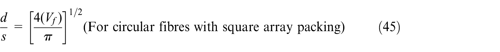
However, in case of woven composite with yarn, it is found when the fibre volume fraction is relatively high (


Where
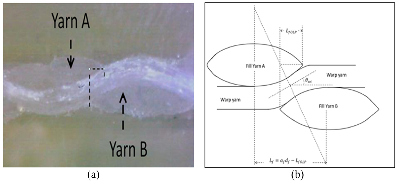
(a) An image showing overlap between neighbouring yarn in a till fabric and (b) schematic drawing change the straight part, also drawing a unit cell with location of this figure, also for twill, plain and satin, mark the straight part and crimp part.
Calculate fibre volume fractions for different fabric structures
In this section, volume of warp yarns
Plain weave
The unit cell definition of a plain weave fabric is presented in Figure 7. 50 The configuration of this unit cell is already given in Figure 5.

Unit cell definition of a plain weave fabric.
The volumes of warp yarns,


The volume of unit cell,


where k is the fibre packing fraction, which normally range between 0.6 and 0.8.
For the high fibre volume fraction configuration shown in 5,


Satin weave
The unit cell definition and fibre undulation of a satin weave fabric given in Figure 8.
50
For a general configuration, the volumes of warp yarns,


For a high value of volume fraction of configuration, above expressions change into:


Unit cell definition of a satin weave fabric. 50
Elastic property of woven lamina composite
The materials researched here are two types of fabrics know as plain glass and satin Kevlar fabrics. In this regards, the following section described the process of determining the elastic properties of lamina composite based on constituent material properties, fabric geometry parameters and weave type. Compliance matrix of different partitions in weft/fill yarn, including the straight part outside the crimp, the straight part in warp and crimp part in warp, are calculated separately and then assembled to obtain the final compliance of weft/fill yarn. The compliance of woven composite lamina consists of contribution from the matrix and yarns (i.e. weft yarn and fill yarn).
Compliance matrix of matrix
The matrix used is epoxy with isotropic properties. The compliance of matrix epoxy is given below:

Where
Compliance matrix of yarn
The coordinate system of a crimp yarn sub-volume in a woven composite showed in Figure 9. The local coordinate system is shown as 1–2–3 where 1 is at the yarn direction. The global coordinate system is shown as x–y–z, where x, y and z-axes are in the warp, fill and thickness direction of composite panel.

Coordinate systems of a crimp yarn in woven fabric reinforced composites. 49
Due to the crimp nature of woven fabric, the global coordinate system is not coinciding to the local coordinate system. Then, the compliance matrix of yarn in the local coordinate system is transformed to a compliance matrix in global system by:

Where
The mathematical equation of

where the elastic modulus, shear moduli and Poisson’s ratios are obtained from the fibre (Glass/PP) and matrix (epoxy) material properties. The hybrid yarn can be regarded as a transverse isotropic material. Previous studies51–53 on longitudinal elastic properties of interlayer hybrid composite demonstrated that elastic modulus obey a linear rule of mixtures. Same rule is used here to calculate the elastic properties of the yarn based on experimentally measured fibre volume fraction.

where m = cos

The compliance for the crimp part in the warp of a fill yarn can be obtained by changing subscript
The compliance matrix of woven fabric is obtained by assembling contribution from three parts:

The two indexes
Geometric parameters of woven fabrics reinforced epoxy.

The compliance of fill yarn can be obtained by exchange subscript
Averaging method to determine elastic properties
If external load is applied in the warp or fill yarn direction, iso-strain assumption is typically applied in calculating elastic properties. Thus, the stiffness matrix is applied in the volume averaging. If external load is applied in the thickness direction of the plate, iso-stress state is assumed and compliance matrix is used in volume averaging. 49 The compliance matrix and stiffness matrix for iso-strain and iso-stress condition can be described as:


Where

The elastic properties of composite lamina for each type of fabric are calculated using Matlab code.
Model validation and parametric studies
The geometry factor and material properties for both a glass woven lamina composite with satin fabric and Kevlar woven lamina composite with plain fabric types are given in Table 4. Calculated elastic properties are compared with experimentally measured data.
Fabrics parameter of a satin glass and plain Kevlar fabrics reinforced composite.

Validation with analytical model
The elastic properties of woven fabric lamina for both satin glass and Kevlar plain fabrics, which extracted from the geometric parameters model, are also compared with the properties that adopted from Chamis model 54 and the micro-mechanical relationships to calculate the elastic constants of yarns, given by equations (33) to (37):


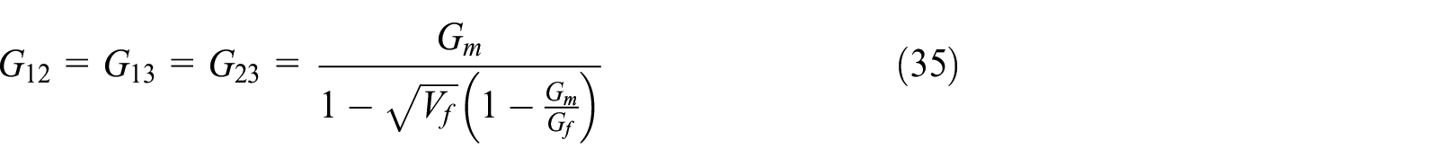


Where
Simulation tensile strength of hybrid composite laminates
In this work, it decided to adopt the Abaqus/Explicit analysis method because the steps of this analysis an handle large deformations, nonlinear material model and multiple contacts and the time spent for running the analysis has significantly reduced.
In this simulation, Abaqus /CAE input file generates the laminates for modelling and rectangular part is modelled as a 3D deformable solid with continuum shell elements (SC8R) in a CAE Part Module. One lamina is modelled with 0° direction and assigned with density, damage failure of this lamina and elastic properties, which supplied from the above analytical process. In addition, the longitudinal tensile strength (

Where
Where
The mechanical properties such as longitudinal compressive strength (


Where
The two-dimensional Hashin failure criteria,
57
which is available in Abaqus software, used to predict the progressive failure damage of composite laminates with including the sub-option of the damage evolution and damage stabilisation option respectively. In this criterion, four different damage initiation mechanisms, which considered interact independently at the ply level, occurred at the degradation of the composite laminate. These damage failures are tensile fibre failure


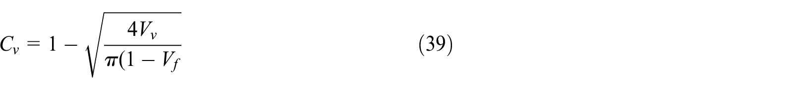
Where, the quantities
The growth of intralaminar damages can strongly influence on the composite laminate stiffness. Therefore, this degradation of the stiffness represented as the plane stress constitutive stiffness matrix in the numerical analysis. This matrix, which has three independent damage indices


The damage indices
The initiation of delamination in the composite laminates characterised by using a quadratic nominal stress criterion, which was also available in the Abaqus software. This criterion assumed that the damage initiate when a quadratic interaction function, which included the nominal stress ratio, reached a value of one as presented in the following expression

Where

Where
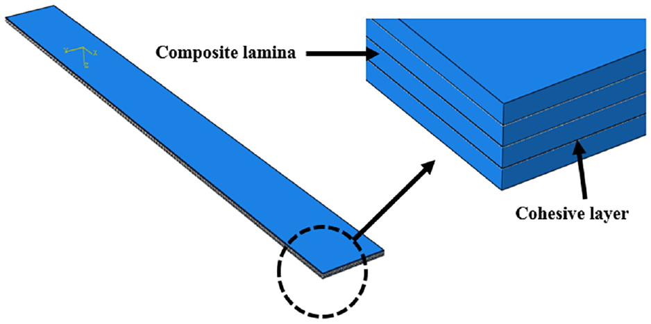
Finite element model of composite laminates.

Boundary condition and loading of composite laminates.
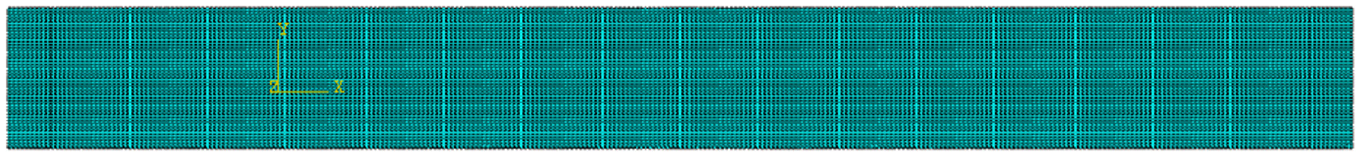
Meshing of composite laminates.
Results and discussions
Tensile strength tests results
The tensile strength tests were conducted experimentaly to investigate the influence of hybridisation based on the hybrid layers on the ultimate tensile strength, which equals to the maximum load divided by the cross-sectional area of tested specimen, Young modulus, strain to failure and toughness of the all composite laminates. The tensile properties results are also listed in Table 5.
Mechanical properties of composites laminates.

Representative stress-strain plots of the hybrid composite specimens have also been illustrated in Figure 13. It can be clearly seen from Figure 12 that the glass composite laminates (i.e. GG samples) exhibit the highest strength and highest slope with linear response until breakage compared to all composites laminates. This is because of the high volume fraction of glass fibres in the loading direction. On the other hand, the stress-strain curve of Kevlar composite laminates (i.e. KK samples), which showed pronounced non-linearity, had more features that are distinct. The first linear part of the curve was considerably appeared up to stress level around 50 MPa and it is called the elastic region. Then, at the end of this portion, the stress-strain curve again became linear until fracture. This second region is called the yielding phase. Thus, the ultimate failure strain is relatively high with around 22 % more than strain to failure of the GG laminates. This is because of higher ductility of Kevlar fibres in the KK composite laminates. These findings are agreed with investigation of Jones and DiBenedetto. 58
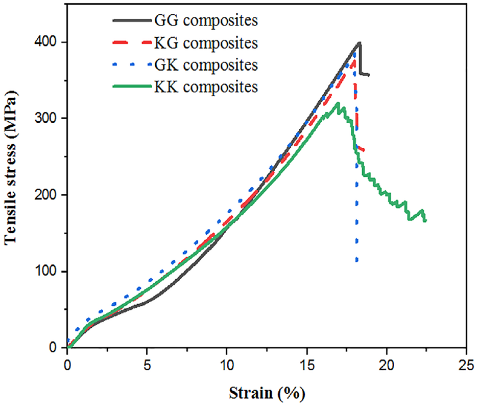
Stress–strain plots of all composite laminates.
Typical stress-strain graphs of hybrid layers composite laminates, that is KG and GK laminates can be also observed in Figure 13. There is a combination of high stiffness and strength properties from the glass fabric and the higher strain to failure properties from Kevlar fabric layers. Thus, the tensile strength of hybrid layers composite (i.e. KG and GK laminates) were slightly lower than the glass composite laminates, but their tensile strength are approximately 1.21, and 1.20 times higher than KK laminates. At the same time, compared to strain–to-failure of glass laminates, an improvement is observed.
Additionally, Figure 14 presented the average values of tensile strength, a modulus of elasticity, strain to failure and toughness for all composite laminates. It can be noticed that the strength and stiffness of composite laminates are strongly depended on the glass volume fraction as seen in Figure 14(a) and (b). Meanwhile, the strength and stiffness of Kevlar composite laminates appeared lowest values due to the lower strength and stiffness of Kevlar fibre.

Mechanical properties (a) tensile strength, (b) modulus of elasticity, (c) strain to failure and (d) toughness of all composite laminates.
Elongation and strain to failure of composite laminates are presented in Figure 14(c). It is observed that the elongation of the glass woven laminates is lower than the other laminates; meanwhile, the elongation is appeared higher in the Kevlar woven laminates. The strain of the woven fabric strongly depends on the strain of the individual fibres, which can sustain while they are subjected to tensile loading. So that, the Kevlar fibres have extra length between jaws and are stretched more compared to glass fibres during tensile test. The hybrid layers laminates showed values of elongation are moderate between glass and Kevlar fibres. The relation of toughness with layers hybridisation is also presented in Figure 14(d). The toughness value are measured from integrated area under stress-strain curves. It can be seen from Figure 14(d) that the high value of toughness has been achieved at Kevlar woven laminates, followed by medium value at hybrid layers composites (KG and GK laminates) and lastly the lowest values have been obtained at glass woven laminates. The improved toughness of Kevlar woven laminates is strongly attributed to the high strain to failure of Kevlar fibres.
Comparing the numerical analysis with experimental results
The summary of elastic constants of composite lamina, which are predicted through the analytical and geometric model, and employed for the FEA model are listed in Table 6. It can be seen that the longitudinal moduli (
Elastic and mechanical properties of composite laminates.

Further, the experimental curves of stress-strain were graphically compared with curves that obtained from FEA model for all composite laminates and presented in Figure 15. Generally, it can be observed that the model curves have a good matching with the experimental plots in the elastic domain. However, the model results exhibited higher stiff composite laminates, where the curves close to y-axis compared to the experimental results. This is due to the crimp effect, which can play role for enhancement the ductile behaviour of woven laminates under tensile loading and the influence of this crimp are not include in the model calculation.

Comparison between the results experimentally obtained and the ones obtained by FEA concerning the stress-strain plots in the case of: (a) GG laminates, (b) KG laminates, (c) GK laminates and (d) KK laminates.
Figure 16 illustrated the displacement of all composite laminates on the direction of applying load. Clearly, it can be seen that the glass woven composite showed lowest displacement (Figure 16(a)) compared to all composite laminates and this was because of higher volume fraction of higher stiffness of glass fibres, meanwhile, Kevlar woven composite laminates presented highest displacement at same load compared to all composite laminates (Figure 16(d)). The tensile load displacement response of hybrid composites as shown Figure 16(b) and (c) having different values and theses values are better than glass woven response. Hence, it is established that the hybrid layers composite laminates would be the convenient design.

Distribution of displacement in the direction of applying load in case of: (a) GG, (b) KG, (c) GK and (d) KK composite laminates.
Conclusion
Experiments conducted in this study for investigation the mechanical properties of composite laminates by selective hybridisation at lamina levels. Hybrid layers composite are produced via combining high-strength layer (i.e. glass woven layer) and high-toughness layer (i.e. Kevlar woven layer). Regarding their influence on the mechanical properties, two types of hybrid layers composite laminates were developed via vacuum assisted resin infusion method and compared with glass composite laminate and Kevlar composite laminates only. The mechanical properties of the hybrid laminates are investigated by using tensile strength tests. Furthermore, the finite element analysis with aiding Abaqus software has been used to simulate the mechanical performance (i.e. tensile strength properties) of hybrid composite laminates. Hashin failure criteria and cohesive elements have been utilised (or proposed or adopted) in this model for prediction the intra-lamina and inter-lamina damage failures respectively in the laminates. In addition, the elastic constants of woven fabric layers, which are used in this numerical study were predicted through geometric model based on the textile geometry and analytical methods in order to assertion accuracy the predicted elastic constants. From the mechanical experimental test and simulation results, the conclusions can be drawn as follows:
Tensile strength results showed that the hybridisation of layers could significantly affect the mechanical properties of hybrid composites. The ultimate tensile strength of glass woven laminates are highest compared to the laminate made of Kevlar layers. This is because of higher volume fraction of glass fibres. However, the strength of Kevlar laminates was significantly improved by sandwiching with glass layers (i.e. KG and GK laminates). It was found that the ultimate strength of the hybrid layers (i.e. KG and GK laminates) are higher (∼ 17% and 15%) than Kevlar laminates. However, rupture strain of hybrid layers composites was reduced compared to that of Kevlar laminates.
According to comparison between the simulation and experimental results based on the global impact parameters, the simulation illustrated more efficient in term of CPU time (lower computational cost) and its predication for tensile strength are more promising compared with experimental results.
The elastic constants predicted through geometric model and analytical methods were compared and show a good matching between them.
The proposed simulation predicted well different failures mechanisms in the composite laminates during the tensile strength tests, that is shear damages, matrix cracks and fibre fractures. Although, the current simulation are reliable for prediction damage failure which are available in composite laminates have glass fibre only, it seems that the level of accuracy decreases with increasing number of interfaces of constituents inside the composite laminates for instance, hybrid composite laminates. This way, further improvements in computational efficiency of mode can be achieved by using VUMAT subroutine to predict the failures occurred in hybrid yarns composite laminates.
Footnotes
Declaration of conflicting interests
The author(s) declared no potential conflicts of interest with respect to the research, authorship, and/or publication of this article.
Funding
The author(s) received no financial support for the research, authorship, and/or publication of this article.