
Abstract
The buckling behavior of latticed columns had been widely investigated based on the theory of Euler, Engesser and Timoshenko shear beam. Although these methods had been formulated and proved to be accurate in case of special assumptions, the influences of lacing bars on the buckling behavior of latticed columns were unclear. This paper modeled a general four-legged latticed column to study the influence of the cross-section characteristics of lacing bars along with their imperfections on the buckling capacity of latticed columns. Three loading conditions and four geometric imperfect models were built to testify the performance of lacing bars. To calculate the buckling load of latticed columns with imperfections accurately, advanced nonlinear analytical procedures using Newton-Raphson incremental-iterative method (ANAP-NR) and Risk arc-length incremental-iterative method (ANAP-Risk) were developed, and then validated by FE software ABAQUS. The current data in the paper show the maximum variation on the critical buckling load of latticed columns, caused by the cross-section area, the bending moment of inertia outer lacing plane, and the imperfections of lacing bars, could reach 68%, 30%, and 25%. The analytical results indicate the great importance of lacing bars on the buckling capacity of latticed columns.
Introduction
Latticed columns have extensive applications in structural engineering, such as electricity industry, factory buildings, bridges, tower cranes, partly seen in Figures 1 and 2, providing economical solutions in case of large span and heavy load. Composed of legs (chords/flanges) and lacings, the latticed columns can be generally grouped into two main categories: laced and battened latticed columns decided by the type of lacings. The present work is to investigate the first one with four legs, whose lacings consist of transverse and diagonal bars (Figure 3).

Applications in electricity engineering.
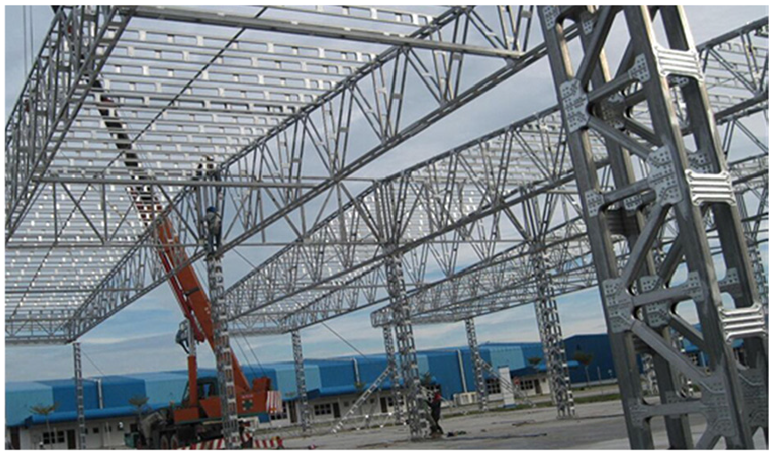
Applications in building engineering.

Structual 3-D model for the four-legged latticed columns: (a) the cross-section profiles, (b) the expressions of the deformations of chord element section, and (c) the direction of bending deformation of lacing bars.
Nearly all the present researches on the buckling capacity of latticed columns were based on the theory of Euler, Engesser or Timoshenko shear beam. Two main issues based on those theories were the buckling modes and the influence of nonlinear factors. The buckling modes included flexural buckling, torsional buckling, flexural-torisonal bucking, and their interactions of global and local buckling modes. Razdolsky1–7 proposed a statically indeterminate method to calculate Euler elastic stability with pure flexural and twisting buckling loads of latticed column. Different latticed columns with fir-shaped lattice, crosswise lattice, serpentine lattice and battened lattice were investigated and contrasted with the results of Eurocode 3 (EC3). 8 These analytical results showed the design code EC3 was in need of revisions because of its higher values in forecasting the critical buckling load of latticed columns. Channel battened columns were studied by Ren et al. 9 using piecewise cubic Hermit interpolation (PCHI) to express the rotational displacement function of column during flexural-torsional buckling deformation. It found that flexural-torsional buckling was prior to happen than pure flexural buckling for channel-section columns, which would be affected by the geometric characteristics and eccentricities.
Another issue is the influence of the nonlinear factors, such as shear deformations and initial geometric imperfections. Kalochairetis and Gantes 10 investigated the interact influence of initial global and local geometric imperfections on the collapse buckling load of I-section laced columns. By replacing the bending rigidity with an effective value of the imperfections, the buckling calculation of latticed columns with imperfections becomes formulaic and convenient. Then transversely loads and arbitrary supports of laced columns were studied in Gantes and Kalochairetis. 11 Approximate second-order analysis of imperfect Timoshenko member considering the above two issues was conducted on different boundary and load conditions of I-section laced columns. Li et al. 12 deduced the strain energy expressions of three typical lacing bars systems, X-lacing, K-lacing, and E-lacing based on the potential energy functions for laced columns. The interactions of global and local imperfections were concerned to track the buckling equilibrium path of load-displacement curves.
In those theories of Euler, Engesser, and Timoshenko shear beam, a common assumption is that the bars or battens behave as a shear panel continuously connected to chords. Although it is simplified to consider lacings and chords of the latticed columns as an indivisible component, there exist two problems in the analytical process. One is the forecasting of the collapse buckling load was inaccurate, usually in upper limit due to the assumption. The other is that the influence of geometrical characteristics of the individual bars or chords on the buckling capacity of the whole columns cannot be distinguished clearly.
Direct analysis of Finite Element Method and Advanced Nonlinear Analysis Method had proved more sophisticated without so many assumptions as traditional theories, but rarely seen in the buckling computation of latticed columns. In fact, both chords and lacing bars could behave as beam-column component between connected nodes in the direct analysis. Equilibrium path of bucking deformation could be acquired precisely with the iterations of nonlinear stiffness matrix using the numerical solution algorithms. Kim et al. 13 and Nguyen and Kim14,15 presented an advanced analysis method of three-dimensional steel frame structure, which can consider the geometric and material nonlinearity of each component accounting for lateral-torsional buckling. Initial geometric imperfection with member and frame were considered in the advanced analysis.16,17 Steel frame with random geometric imperfections was integrated in the advanced second-order nonlinear analytical procedures. Fooladi 18 proposed a new super-element of bars and chords components with twelve degrees of freedom to construct the finite element model of latticed columns. The characteristics of cross-section area, moments of inertia, shear coefficient, and torsional rigidity of lacing bars and chords could be counted entirely in the FE procedure.
Note that many modeling experiments had validated the importance of lacing bars. Kalochairetis et al., 19 Bonab et al., 20 Yang et al.,21,22 and Chen and Ou 23 conducted the experimental studies on the two-legged, three-legged and four-legged laced latticed columns, respectively. These testing results investigated the influence of columns’ characteristics on the buckling capacity of latticed columns, such as eccentricity, types of lacing bars, chords’ cross-section, panel’s length, material of specimen, diameter-to-thickness ratio of the tube section, etc. Mirtaheri et al.24,25 optimized the buckling capacity of the Buckling Restrained Brace (BRB) steel core, and derived the formula for the best length of BRB through the numerical method and experimental validation. Aghoury et al.26,27 experimentally investigated the buckling behavior of battened latticed columns composed of four equal slender angles. The ratio between geometrical characteristic of battens and chords were tested to play great roles on buckling behavior and collapse loads of whole columns. To validate the accuracy of experimental results, the geometric imperfections, loading defection and residual stress were considered with finite element simulations of ABAQUS.
In this paper, both linear and nonlinear buckling analyses are conducted to investigate the influence of the characteristics of lacing bars along with their imperfections on the buckling capacity of latticed columns. Firstly, the linear buckling load was calculated considering three loading conditions, no eccentricity unidirectional eccentricity
Structural model
Typical 3-D structural model for the four-legged latticed columns consists of four identical legs (chords) and four-plane lacings (lacing bars), seen in Figure 3. The lacing bars were fixed (welded or bolted) regularly on the chord. The two ends of the columns were connected by the end plates, where one end was fixed on the ground with all freedom constrained, and the other was loaded by an eccentric compression load
The cross section of chords is equilateral angel steel with dimension
Based on the structural 3-D model for the four-legged latticed columns, a computational model considering the influence of the end plates was plotted in Figure 4. The computational model contains 24 nodes and 60 elements (4 end plate elements, 20 chord elements, 20 diagonal bar elements, and 20 transverse bar elements). The loading end plate was modeled with completely rigid elements with number 57, 58, 59, 60, and the constraint end plate was useless in the computational model because all the freedoms at nodes , , , and had been constrained. The eccentric compression load


Where the equation (1) is the load equilibrium equation, and equation (2)–(4) are the bending moment equilibrium equations.


Structural computational model for the four-legged latticed columns.
The necessary geometric dimensions used in Figures 3 and 4 were listed in Table 1. The cross-section characteristics of chords were calculated according to the dimension
Necessary geometric dimensions of the latticed columns.

Linear buckling analysis of four-legged latticed columns
Computing method for linear critical buckling load
Linear buckling analysis is used to express the structural buckling capacity under perfect conditions without considering initial geometric imperfections and plastic material behavior. Based on the computational model in Figure 4, the type of the chord element is same as the lacing bars but with different cross-section characteristics, so the chord element and lacing bars can be analyzed as a type of element. Figure 5 shows the forces and displacements of this element in system

Wherein, {

The nodal forces and displacements of chord and bar element: (a) in x–z plane, (b) in x–y plane, and (c) in the twisting plane.
The structural equilibrium condition of the whole columns is:

Where {
In the linear buckling analysis, the displacements of the elements, occurring in the pre-buckling state, were assumed to have no influence on the buckling loads. Meanwhile, the external compression load remains unchanged in the pre-buckling state. So the equation (7) in the state of buckling can be written as

Where

In equation (9), the solutions of the load factors
Influence of lacing bars on critical linear buckling load
In previous researches Razdolsky1–7 and Kalochairetis and Gantes10,11 about the linear buckling analysis for latticed columns, the lacing bars are considered as uniform distributed web connected with the chords. Only characteristic of cross-section area
In the paper, the characterizes
Firstly, the parametric research focus on distinguishing the influence of parameters
Compared the left and right figure of Figure 6(a), when the moment of inertia inner lacing planes
Compared Figure 6(a)–(c), loading eccentricity would greatly reduce the buckling capacity of latticed columns. When the loading eccentricity (

Influence of parameters
Then, to clearly show the influence of the cross-section area
The critical load
The loading eccentricity

Influence of parameter Ad of lacing bars on the critical linear buckling load λmin: (a) no eccentricity, (b) unidirectional eccentricity with ex = 20 mm, and (c) bidirectional eccentricity with ex = ey = 20 mm.
Nonlinear buckling analysis of four-legged latticed columns
Initial geometric imperfection models
There always exist initial geometric imperfections for the latticed columns. In the design stage, The European code EC3 allowed the maximum amplitude le/500 with the imperfect type of single sine wave. However, in the stage of real structural engineering, the imperfect modes of latticed would be arbitrary, overlapping, and unpredictable. Imperfect types of double sine wave or maximum imperfections exceeding the amplitude le/500 are also commonly seen in the real latticed columns, seen in Figure 8(a) and (b).

(a) Imperfect type-1 of lacing bars and (b) imperfect type-2 of lacing bars.
To investigate the influence of the lacing bars imperfections on the critical buckling of latticed column, four typical imperfect models in structural engineering were designed in Figure 9, including single and double sine wave imperfections of the lacing bars. Table 2 lists the numerical expressions of each imperfect model. Where

Imperfect models of lacing bars: (a) Model_1, single sine wave outer lacing plane, (b) Model_2, double sine wave s inner lacing plane, (c) Model_3, double sine wave outer lacing plane, and (d) Model_4, single sine wave outer lacing plane (many lacing bars).
Numerical expression for the initial geometric imperfections of the lacing bars.

Expressions of the stiffness matrix of lacing bars with imperfections
Figure 10 shows the deformed condition of lacing bars element and nodal forces with initial geometric imperfections v0(x) in

The deformations and nodal loads of element of chord and lacing bars in x–z plane.
Taking the unidirectional bending deformation v(x) for example, the general expression in Table 2 of bending deformation imperfections v0(x) is

Where v0m = le/N is the amplitude of lacing bars imperfections; n = 1 or 2 represents the single or double sine wave of imperfect lacing bars, respectively.
The bending differential equations for the lacing bars’ displacement v(x), considering the imperfections v0(x), is defined in equation (11).

Let

In equation (12),

Introduce the boundary conditions v(x = 0) = vi and v(x = l) = vj into equation (12), then coefficient

Substituting

Combined equations (12), (14) with the mechanical equilibrium conditions between the two end points of elements
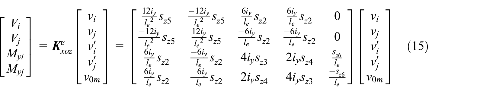
In equation (15),


Similarly, the elastic stiffness matrix

Where


Then, the elastic stiffness matrix [
Nonlinear solution algorithms
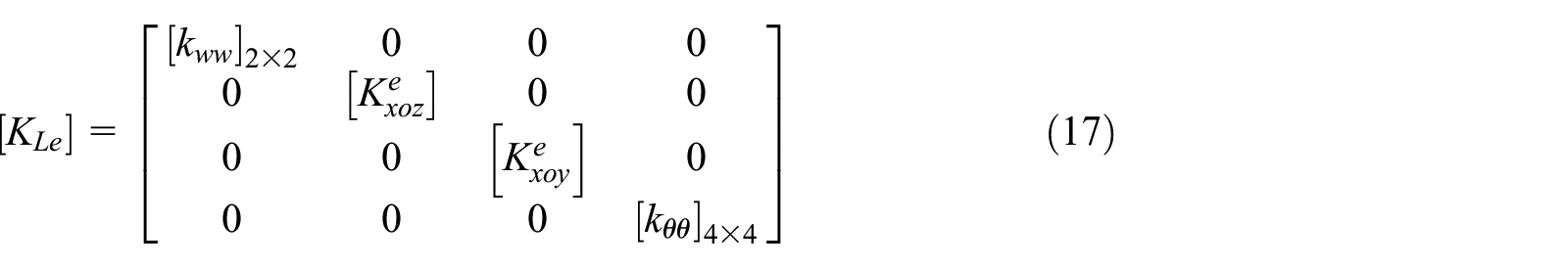
In order to trace the nonlinear equilibrium path of the four-legged latticed columns under compressive load, two kinds of nonlinear solution algorithm, Newton-Raphson load incremental-iterative method and Risk arc-length incremental- iterative method were introduced in Figure 11.
Iterative processes of Newton-Raphson method and risk constant arc-length method.
In the Newton-Raphson load incremental-iterative method (Figure 11(a)), the external force would be loaded in several steps with equal or unequal interval. Iterative process occurs in each load step to eliminate residual force between external force and internal nodal force. This method is sensitive to convergence failures and uncontrollable in snap of critical point of load-displacement curve. To meet the shortcomings of Newton-Raphson method, arc-length control method is developed in Risk constant arc-length approach (Figure 11(b)).The solution scheme was controlled by arc length consisting of nodal displacements and forces. This method could capture the whole equilibrium path efficiently and solute snaps back and snap through response successfully. Because of the superior performances, it had been integrated in most commercial nonlinear FE software ANSYS, ABAQUS, NASTRAN, etc.
Once the tangent matrix of bars and chords was assembled to the global stiffness of the latticed columns, the increment equilibrium equation can be written as

Wherein, [
For Newton-Raphson increment approach, the unbalanced force in iterative step

{

For Risk constant arc-length approach, the constrained arc length in each load step is

The convergence criteria in iterative process is

In equations (19)–(22), {
Procedure development with nonlinear solution algorithms
Based on section 4.1–4.3, the advanced nonlinear analytical procedures ANAP considering the initial geometric imperfection of lacing bars were developed. Figure 12 showed the flowchart of the analytical procedures ANAP-NR and ANAP-Risk, developed with solution algorithms Newton-Raphson increment method and Risk arc-length increment method, respectively. As integrating the stiffness matrix of imperfect element, the procedure solvers could acquire the nonlinear buckling equilibrium path of the imperfect models in Figure 9.

Advanced nonlinear analytical ANAP-NR and ANAP-risk.
The process of the analytical procedures in Figure 12 can described as the following steps:
1. Calculate the elastic stiffness matrix [
2. Transfer the matrix [
3. Solve the incremental equilibrium equation ([
4. Apply nonlinear numerical iterative strategy of Newton-Raphson and Risk arc-length solution algorithms to eliminate residual force or displacement. The iterative principle of the two methods had been shown at Figure 11 in section 4.3.
For Newton-Raphson load increment iteration, the step length of every load step [
For Risk arc-length increment iteration, the load step were controlled by arc length

Where
5. After the convergence process of iteration completes in current load step, update the structural stiffness matrix of the latticed columns and prepare next load step. Print the equilibrium point consisting of nodal load vector
Results and discussion
Four imperfect models in Figure 9 were solved by the advanced nonlinear analytical procedures (ANAP) in Figure 12. The purpose was to find the influence of lacing bars imperfections on the nonlinear buckling behavior of the four-legged latticed columns. To verify the solution accuracy of the analytical procedures ANAP, the nonlinear FE analytical software ABAQUS was introduced in section 5.2. Corresponding FE imperfect models were built, and then the nonlinear buckling analytical technique ABAQUS-Risk, having integrated Risk increment-iterative method already, was conducted to accurately track the nonlinear equilibrium path of the imperfect columns.
Effect of lacing bars imperfections
Figure 13(a)–(d) show the nonlinear equilibrium path with the load-displacement curves of the four imperfect models. Point_1–Point_4 were the test nodes, corresponding to the node , , , and in Figure 4.

Equilibrium path with the load–displacement curves: (a) Model_1 on the left, (b) Model_2 on the right, (c) Model_3 on the left, and (d) Model_4 on the right.
From Figure 13, it can be seen the developed procedure of ANAP present a good performance in tracking the load-displacement equilibrium path of the imperfect latticed columns. Compared to the results of ABAQUS-Risk, method APAN-NR lead to the maximum error 2.01% of the critical load from in solving Model_1, and the maximum error −6.25% of the critical displacement in solving Model_2. Meanwhile, method ANAP-Risk just has errors with the critical loads ranging in 3.06%–6.88%, and the critical displacements ranging in −0.03% to 7.18%. However, method ANAP-Risk has the advantage of tracking the declining stage of the equilibrium path, which cannot be achieved through ANAP-NR method.
What’s more, the critical buckling load
Different imperfect models of lacing bars have significant impact on the critical nonlinear buckling load and equilibrium displacements. It can be seen that the critical load of imperfect Model_4 is 327 kN (ABAQUS-Risk), which declined approximately 21.5% than that of Model_2 with the critical buckling load 417 kN. Imperfect model with many lacing bars’ imperfections would decrease more shapely the nonlinear buckling capacity of the latticed columns. The analytical results directly indicate the important influence of lacing bars imperfections on the critical buckling capacity of the four-legged latticed columns.
Compared the critical buckling loads of Model_2 and Model_3, the model with the imperfection of lacing bars outer lacing plane would bring more reduction for the buckling capacity of latticed columns. Under same imperfections of lacing bars with element number 16 and 40 in Figure 9, current data show the buckling load of Model_3 with imperfections outer lacing plane is about 17.03% (from 417 to 346 kN) less than that of Model_2 with imperfections inner lacing plane.

The critical buckling load and displacement for the four imperfect models: (a) the critical load and (b) the critical displacement refereeing Point_1 (node ⑩ in Figure 4).
Verification with FE shell-beam models of ABAQUS
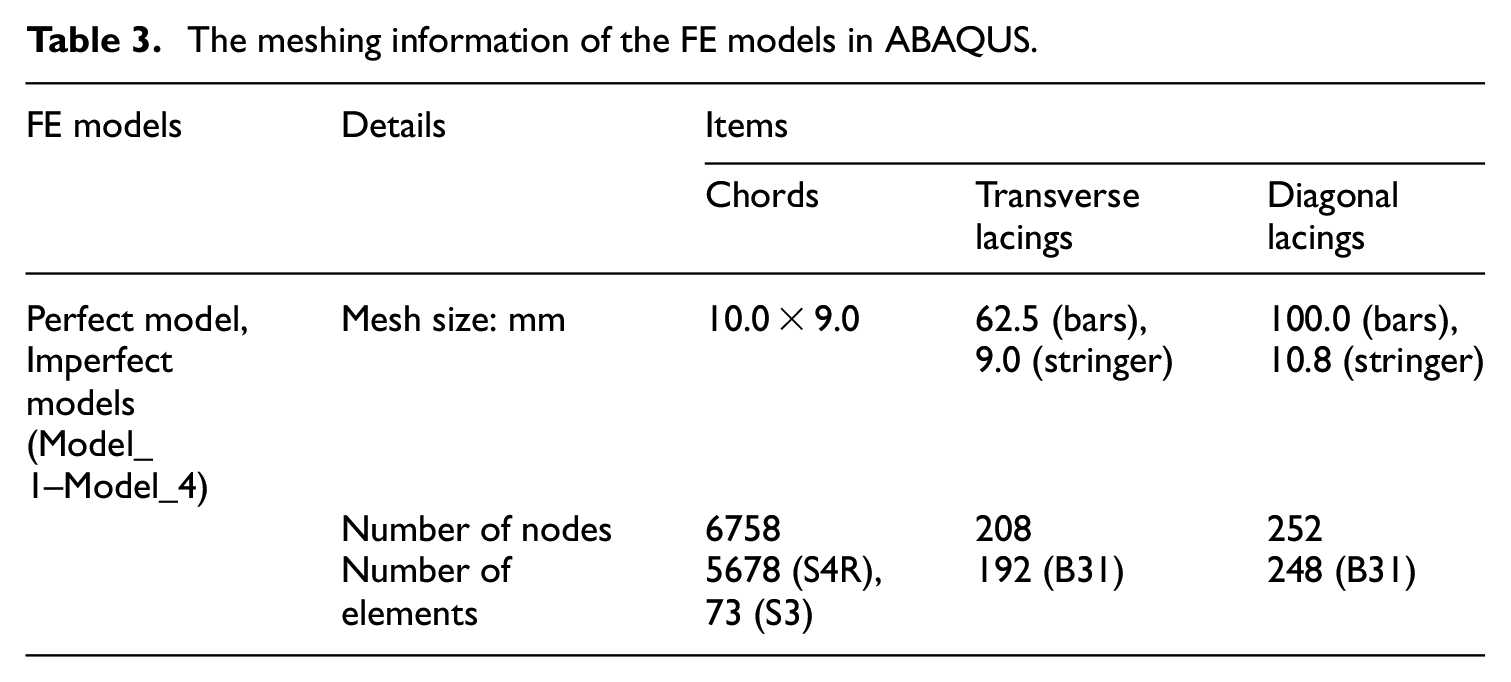
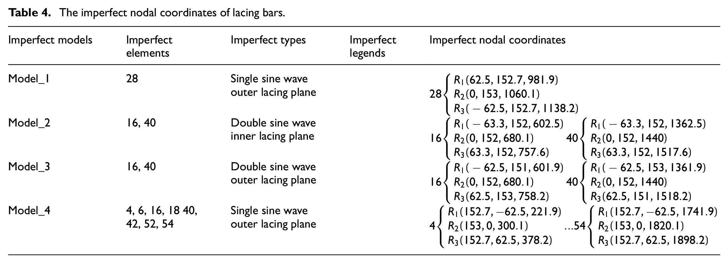
Most commercial FE software has integrated the module of geometric nonlinear buckling analysis. In this paper, Perfect four-legged latticed columns were modeled using nonlinear FE software ABAQUS (Figure 15) to validate the advanced nonlinear analytical procedure ANAP. The chords and lacing bars were built with 4-node shell element S4R, 3-node shell element S3 and 2-node beam element B31, respectively. The meshing information of the FE model is listed in Table 3. The transverse and diagonal lacing bars were divided to four elements with meshing size 62.5 and 100.0 mm, respectively. The four imperfect models Model_1–Model_4 would be created automatically by modifying the nodal coordinates of the imperfect lacing bars with the imperfect nodal coordinates

Perfect FE model and its modeling techniques for the four-legged latticed columns in ABAQUS.
The meshing information of the FE models in ABAQUS.
The imperfect nodal coordinates of lacing bars.
Modeling techniques in ABAQUS were introduced and shown in Figure 16. The technique of master-slave nodes coupling technique was used to simulate the influence of the end plate in the loading and constraint plates. Meanwhile, the beam-shell stringer coupling technique was used to simulate the shared connected sections in chord and lacing bars.

Modeling techniques used in the ABAQUS platform.
In the nonlinear buckling analysis of ABAQUS platform, all the parameters setting were the same as the developed analytical procedure ANAP-NR and APAN-Risk. The nonlinear load-displacement equilibrium curves of method ANAP-NR, ANAP-Risk, and ABAQUS had been plotted in Figure 13. The corresponding critical buckling loads of the imperfect models were listed in Table 5. Meanwhile, Figure 17 showed the equilibrium path of the four imperfect models under the critical buckling conditions. It can be seen the imperfections of lacing bars have great influences on the bucking load and equilibrium path of latticed columns. The maximum computational errors of ANAP-NP and ANAP-Risk are within the variation of [−2.09%, 2.17%] and [2.97%, 6.92%], compared to the method of FE models in ABAQUS platform. The proposed methods ANAP have good computational accuracy.
The comparison of the critical buckling loads of the latticed columns based on ABAQUS.
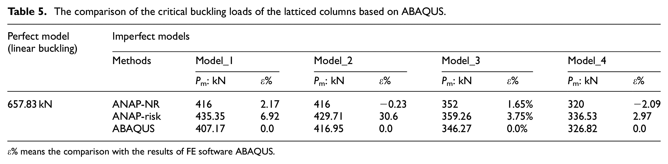
ε% means the comparison with the results of FE software ABAQUS.

Equilibrium path of the four imperfect models based on the geometric nonlinear analysis of ABAQUS.
Comparison with the design code EC3
According to the design code EC3-2005, 8 the latticed built-up columns were smeared as continuous structure, where the lacing bars were considered as continuous web connected with the chords. The failure modes for the elastic buckling behavior of the latticed built-up columns include the global buckling of the whole columns and the local buckling of the chords.
Global elastic buckling of the whole columns considering the loading eccentricity and initial imperfections occurs at the load level

Where


Local buckling is associated with the buckling of chord component between the adjacent lacing joints. The shape of the buckling mode was assumed to be sinusoidal along the length of chord.
Thus, the local elastic critical load

The critical buckling load
The comparison of the critical loads of the latticed columns based on EC3.

ε% means the comparison with the results of EC3.
Summary and conclusions
Linear and nonlinear buckling capacity of four-legged latticed columns was investigated in the study. The key purpose was to highlight the importance of lacing bars, including their cross-section characteristics of cross-section area
Based on the outputs of the linear and nonlinear buckling analysis with method ANAP-NR, ANAP-Risk, and ABAQUS-Risk, the following main conclusions were drawn.
The assumptions in previous research of Razdolsky and Kalochairetis that ignored the bending moment of inertia of lacing bars in calculating buckling load of latticed columns need to be revised. The current analytical data found the critical buckling load of latticed columns could improve sharply with growth ratio 30%, when the bars’ bending moment of inertia outer lacing plane
There exists a threshold cross-section area
The initial geometric imperfections of lacing bars would obviously decrease the buckling capacity of latticed columns. In this paper, the different imperfect model could cause the maximum declination of the critical buckling load with 21.5% from 416.8 kN (Model_2) to 327 kN (Model_4). What’s more, Imperfect models with lacing bars outer lacing plane or many lacing bars’ imperfections would decrease more sharply the buckling capacity of the four-legged latticed columns.
The analytical results validate the accuracy of ANAP developed in the study. When the parameters of nonlinear solution algorithm in each load step were set reasonably, the ANAP present a good performance in solving the nonlinear buckling capacity for the imperfect models. In this study, the maximum error of ANAP-NR and ANAP-Risk is 6.88% and 7.18%, compared with the results of FE validated method.
Footnotes
Appendix
The elastic stiffness matrix [
The geometric stiffness matrix [
Where
Declaration of conflicting interests
The author(s) declared no potential conflicts of interest with respect to the research, authorship, and/or publication of this article.
Funding
The author(s) disclosed receipt of the following financial support for the research, authorship, and/or publication of this article: National Natural Science Foundation of China (NSFC) supports the author under grant number (No.) 10772052 (Working) and 51178121 (Finished).
Data availability statement
All the data, models, or codes that support the findings of this study are available from the corresponding author upon reasonable request.