
Abstract
Due to the rail-bridge thermal interaction, the high additional axial force in continuously welded rails on continuous bridges may lead to rail buckling or breaking. However, there is little research on the influence of the location of the fixed bearing of continuous beam on the additional force of rail. In order to study the influence of bridge bearing arrangement on the additional longitudinal force of CWR, the thermal interaction model is established for rail, and simple and continuous beams considering nonlinear stiffness and the methods are proposed to determine the locations of fixed bearings of continuous beams corresponding to the maximum additional forces in rail reaching minimum values. Multiple continuous beams with several different lengths and simple beams with three types of bearing arrangements are taken into account to find the effect laws of the locations of the fixed bearings of continuous beams on the maximum additional forces in rail. The results show that as long as the same number of continuous beams, the ratios of the distances of adjacent two fixed bearings to the distance between the two fixed bearings of the simple beams neighbour to the first and last continuous beams respectively are approximately equal to each other. Furthermore the appropriate locations of the fixed bearings of continuous beams are recommended. The results can guide designing the location of the fixed bearing of continuous railway bridge while reducing the additional axial force in continuously welded rails due to bridge thermal effect.
Keywords
Introduction
A larger number of continuously welded rail (CWR) track are laid on railway bridges. The high additional axial force in CWR due to the rail-bridge longitudinal interaction caused by the temperature change of bridge may lead to rail buckling or breaking. Thus, the problem of the rail-bridge thermal interaction has been gained wide attention. In the early stage, the analytical methods were mainly used. Frýba1,2 and Esveld 3 put forward basic differential equation and analytic solutions of the additional thermal force of CWR on simply or continuously supported bridges considering linear stiffness.
Then, the numerical or field measurement methods were mainly employed by many scholars. For example, Larsson and Karoumi 4 established a finite element model to predict the thermal effect in a hollow concrete section. Kašpárek et al. 5 and Carvalho et al. 6 monitored the rail-bridge interaction under daily temperature cycle for a long time, and proposed a new method to determine the given rail safety and buckling temperatures by using ANASY finite element software. Mirza et al.7,8 used the finite element software ABAQUS to study the mechanical properties of rail-bridge systems under the action of thermal load and different levels of seismic load. Zakeri et al.9,10 analysed the lateral resistance of frictional concrete sleepers and proposed the new definition for variations in neutral and float temperatures in CWR. Mosayebi et al. 11 studied the effects of continuous or discrete supports, V-shaped rail irregularity and geometrical stiffness on the vehicle-track dynamic interaction. Jiang 12 analysed the transmitting ways of the rail-bridge longitudinal interaction. Chen et al. 13 studied the influence of several factors on the additional longitudinal force of CWR on continuous beams with linear stiffness. Ruge and Birk 14 and Ruge et al. 15 investigated the longitudinal forces of CWR due to rail-bridge interaction considering nonlinear characteristic. Okelo and Olabimtan 16 analysed the nonlinear rail-structure interaction of an elevated skewed steel guideway by using the commercial software GT STRUDL. Zhang et al.17,18 obtained the fastener resistance parameter in the laboratory and studied the rail-bridge interaction of a long-span bridge. Alfred et al.19,20 used the monitoring-based nonlinear finite element modeling to research the rail-bridge structure interaction. Yun et al.21,22 measured and investigated the response of the rail-bridge interaction caused by the temperature change. De Backer et al. 23 used finite element method to research the application limits of CWR on temporary bridge decks. Lou et al. 24 proposed a method to determine the locations of the rail expansion regulator and the fixed bearing of the continuous beam, corresponding to the maximum additional forces of rail reaching minimum values. Yan et al. 25 studied the distribution of the longitudinal force of CWR on suspension railway bridge with length exceeding 1000 m. Wenner et al. 26 analysed the long-term measured data of rail stress and displacement in recent 2 years and compared to those of the model calculation results. Lou et al. 27 investigated the influences of nonlinear stiffness, span number of bridge, constant longitudinal restoring force, bridge bearing arrangement, and span length of bridge on the additional longitudinal stress and displacement of rail for multi-span simply supported bridges. Ramos et al. 28 studied the bridge length limits due to track-structure interaction in continuous girder prestressed concrete bridges. Based on the bilinear resistance model, Dai et al. 29 proposed an analytical algorithm to analyse the track-bridge interaction of long-span steel bridges under thermal action.
Continuous beams are widely adopted in the railway bridge. Compared with the length of simple beam, that of continuous beam is longer, thus the maximum additional force in rail induced by the temperature change of beam is greater. If the location of the fixed bearing of continuous beam is not appropriate, the high additional axial force induced by the rail-bridge longitudinal thermal interaction may lead to rail buckling or breaking. To the knowledge of the authors, few papers have studied the influence of the location of the fixed bearing of continuous beam on the additional force of rail. Therefore, this paper focuses on the issue about the appropriate location of fixed bearing of continuous beam to reduce the additional axial force in CWR. Compared with the existing literature, the new findings and novelties of this paper are below. (1) The effect of the locations of the fixed bearings of continuous beams on the maximum additional force of rail is investigated considering nonlinear stiffness; (2) The methods are presented to determine the locations of fixed bearings corresponding to the maximum additional forces in rail reaching minimum values; and (3) To reduce the additional axial force in continuously welded rails due to bridge thermal effect, the appropriate locations are recommended for the fixed bearing of continuous railway bridges with the different number.
Longitudinal thermal interaction model of CWR track and foundations
The foundations of a CWR track from left to right are considered as embankment, simply supported bridges, continuously supported bridges, simply supported bridges, and embankment. CWR, simply and continuously supported bridges are modelled as beam elements. Each continuous beam has only one fixed bearing and the fixed bearing is assumed to locate at any position below the beam in the numerical analysis. A schematic planar model of CWR track and foundations longitudinal thermal interaction is shown in Figure 1, in which,

Schematic planar model of CWR track and foundations longitudinal thermal interaction: (a) type A of bearing arrangement of simple beams, where
The track between rails and bridge is modelled as coupling shear elements with nonlinear stiffness as shown in Figure 2. The rail-beam thermal interaction descriptions can be found in Lou et al.
27
For convenience, the key statements are listed here. The nonlinear characteristic of the difference


Longitudinal track-bridge coupling element and the nonlinear stiffness law: (a)
where,

where,
If the absolute value of displacement difference

in which, c denotes spring stiffness per unit length in the linear phase, if
If the absolute value of difference

The track between rails and embankment is modelled as longitudinal spring with nonlinear stiffness. Eqs. (1), (3) and (4) can be used in the rail on embankment only by the value of
The mechanics equation of CWR track and foundations longitudinal thermal interaction considering nonlinear stiffness can be found in Lou et al., 27 and are omitted here to reduce the length of this paper. The corresponding program for calculating the additional thermal force in rails of the presented model is compiled.
Verification
A CWR track on single continuous beam and two approach embankments are considered. The parameters are listed in Table 1 from Chinese code,
30
except the parameters of
The parameters of CWR track on continuous beam and embankment.


Distribution of the additional force and displacement in the rail: (a) additional force of rail and (b) additional displacement of rail.
Procedures to determine the appropriate locations of the fixed bearings of continuous beams
The maximum additional tension and compression forces of rail vary with the location of the fixed bearing of continuous beam. When the maximum additional tension and compression forces of rail on two continuous beams reaches their minimum values, the steps to determine the locations of fixed bearings of two continuous beams are as follows.
Firstly, the second fixed bearing is located at the left end of beam.
The first fixed bearing is also located at the left end of beam. Then, the additional force of rail along its length is calculated and their maximum values can be obtained. It should be noted that the maximum and minimum values of compression force refer to the absolute values.
The location of the second fixed bearing remains unchanged. The location of the first fixed bearing is changed from left to right until arriving the right end of the beam, and the changing interval may be adopted the length of beam element.
The maximum additional tension and compression forces of rail corresponding to each location of the first fixed bearing are obtained and their relationship curves are plotted.
The minimum values in the above curves are just those of the maximum additional tension and compression forces of rail while the second fixed bearing is located at the left end of the second continuous beam.
Then, the location of the second fixed bearing is changed from the left to right until arriving the right end of the beam, and the changing interval may be also adopted the one length of beam element. The minimum values of the maximum additional tension and compression forces of rail corresponding to each location of the second fixed bearing are gained by repeating the steps (2)-(4).
The curves of the minimum values mentioned in the step (6) with the location of the second fixed bearing are drawn. The abscissas corresponding to the minimum values in the curves are the locations of the second fixed bearing to be determined.
Finally, the location of the second fixed bearing determined above remains unchanged. Using the steps (3) and (4), the curves of the maximum additional tension and compression forces of rail with the location of the first fixed bearing can be obtained. The abscissas corresponding to the minimum value in the curves is the locations of the first fixed bearing to be determined.
The procedures to determine the appropriate locations of the fixed bearings of three continuous beams are similar to above those of two continuous beams, only with the following modifications. The second fixed bearing in the above procedures is replaced by the third fixed bearing, then the new step, i.e., the second fixed bearing is located at the point
Results
The influence of the locations of the fixed bearings of continuous beams on the maximum additional force of rail, and their locations corresponding to the maximum additional force of rail reaching the minimum value are researched in this section. The foundations of a CWR track are the same as the described in Figure 1. The total number of simple beams is 10 and they are evenly distributed on two sides of continuous beams. The length with 32 m of simple beam is adopted. The 3 types of bearing arrangements of simple beams are considered as shown in Figure 1(a) to (c). Except for the parameter c, the other parameters in Table 1 are adopted in this section. In order to make the obtained representative laws, the continuous beams with different numbers and lengths are considered. The continuous beams with total number of 1, 2, 3, 4 and 5 are used, and the length of
Results of one continuous beam
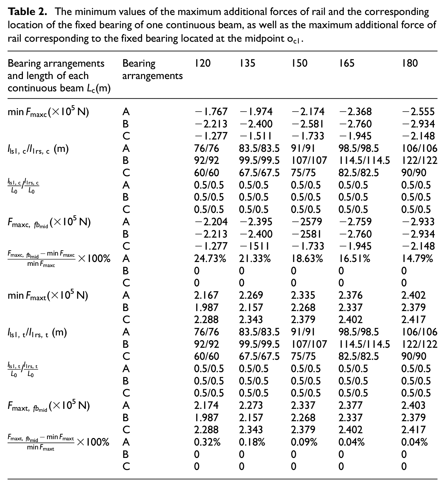
Table 2 lists the minimum values of the maximum additional forces of rail and the corresponding location of the fixed bearing of one continuous beam, as well as the maximum additional force of rail corresponding to the fixed bearing located at the midpoint
The minimum values of the maximum additional forces of rail and the corresponding location of the fixed bearing of one continuous beam, as well as the maximum additional force of rail corresponding to the fixed bearing located at the midpoint
where,
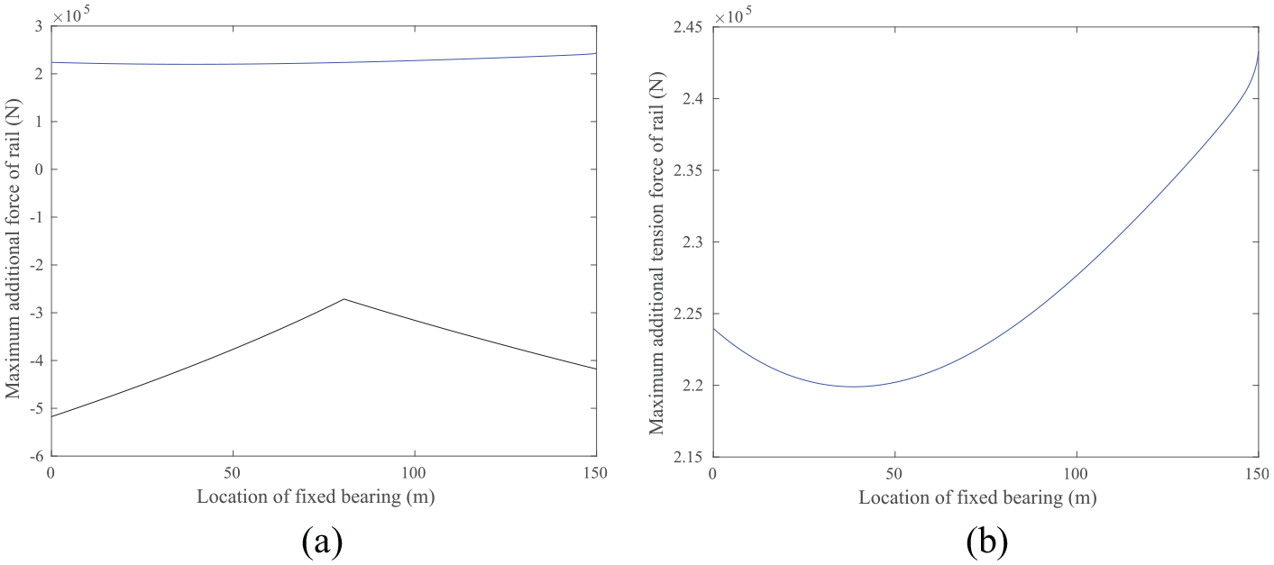
Figure 4 draws the curves of the maximum additional tension and compression forces of rail with the location of the fixed bearing of one continuous beam with
The maximum additional tension and compression forces of rail vary with the location of fixed bearing of continuous beam, and they are distributed symmetrically with the respect to the point of
The location of the fixed bearing of continuous beam has little influence on the maximum additional tension force of rail, but has a very significant influence on the maximum additional compression force of rail. As shown in Figure 4(b), the maximum and minimum values of the maximum additional tension force of rail are 2.115 × 10⁵ N and 1.987 × 10⁵ N, their difference is only 6.44%, however, those of the maximum additional compression force of rail are −3.591 × 10⁵ N and −2.213 × 10⁵ N, their difference is 62.27%. Figure 4(c) shows that those of the maximum additional tension force of rail are 2.394 × 10⁵ N and 2.388 × 10⁵ N, their difference is only 4.63%, however, those of the maximum additional compression force of rail are −2.888 × 10⁵ N and −1.277 × 10⁵ N, their difference is 126.16%.

The curves of the maximum additional tension and compression forces of rail with the location of fixed bearing of one continuous beam with
Results of multiple continuous beams
Symmetrical law
Two continuous beams with

The curves of the minimum values of the maximum additional forces of rail with the location of the second fixed bearing for the case of two continuous beams with
According to the step (8) in the Section 4, their locations remain unchanged, then the curves of the maximum additional compression and tension forces of rail with the location of the first fixed bearing can be obtained and plotted in Figure 6(a) and (b), respectively. Figure 6(a) and (b) show that the locations of the first fixed bearing to be determined are 80.5 and 39 m, respectively. This means that the distances obtained between the first fixed bearing and the point of

The curves of the maximum additional forces of rail with the location of the first fixed bearing for the case of two continuous beams with
Modified procedures for determining the locations of fixed bearings
Based on the above symmetrical law of the fixed bearings, the procedures mentioned in the Section 4 for determining the locations of fixed bearings of two continuous beams can be modified as follows. The modified procedures can significantly improve the calculation efficiency due to the reduction of the number of cycles in the calculation process.
The first and second fixed bearings are, respectively, located at the left and right ends of the beam for the types B and C. But for the type A, the second fixed bearing is located at the distance of
Both the locations of the first and second fixed bearings are changed towards the point
Similarly, if the last paragraph of Section 4 is modified to the above procedure, it can be used to find the appropriate locations of the fixed bearings of three continuous beams. Again, the two continuous beams with
The curves of the maximum additional forces of rail with the location of the first fixed bearing for the case of two continuous beams with
In addition, Figure 7 shows that the tension forces are between 2.199 × 10⁵ N and 2.433 × 10⁵ N, with the difference of 10.64%, however, the compression forces are between −2.715 × 10⁵ N and −5.175 × 10⁵ N, with the difference of 90.61%. This further explains that the location of the fixed bearing of continuous beam has little influence on the maximum additional tension force of rail, but has a very significant influence on the maximum additional compression force of rail.
Minimum values of the maximum additional forces of rail and corresponding locations of the fixed bearings of multiple continuous beams
On the basis of the modified procedures, and the laws mentioned above, the values of
For the same number and length of continuous beams, the bearing arrangements of simple beams have the influence on the values of
Each fixed bearing located at the midpoint
With the same number of continuous beams, for the same length of continuous beam and the same type of bearing arrangement of simple beams, there are
As shown in Table A1, while the maximum additional compression and tension forces of rail reach their minimum values, the locations of fixed bearings of two continuous beams are not same. Most of the values of
With the same number of continuous beams, for the different lengths of continuous beams and the different types of bearing arrangement of simple beams, the distances of adjacent two fixed bearings (including the fixed bearings of simple beams neighbour to the first and last continuous beams) are not equal to each other, however, the ratios of them to
For the same length of continuous beam and the same type of bearing arrangement of simple beams, the distances of neighbour two fixed bearings increase with the number of continuous beams. For example, the values of
Conclusion
The longitudinal thermal interaction model of CWR track, simple and continuous beams considering nonlinear stiffness is established. Then, two methods are proposed to determine the locations of fixed bearings of continuous beams corresponding to the maximum additional tension and compression forces of rail reaching their minimum values. Furthermore, multiple continuous beams with several lengths and simple beams with three types of bearing arrangements are considered to find the effect laws of the locations of the fixed bearings of continuous beams on the maximum additional forces in rail. The obtained results can guide designing the location of the fixed bearing of continuous railway bridge to reduce the additional axial force in CWR induced by the bridge thermal effect. The conclusions are as follows.
With the temperature rise of beam, the location of the fixed bearing of continuous beam has little influence on the maximum additional tension force of rail, but has a very significant influence on the maximum additional compression force of rail. The law will be reversed with the temperature falling of beam.
The appropriate locations are recommended for the fixed bearing of continuous railway bridges with the different number considering rail-bridge thermal interaction. The results can guide designing the location of the fixed bearing of continuous railway bridge while reducing the additional axial force in continuously welded rails.
For two continuous beams, it is not appropriate to arrange the fixed bearings of continuous beams according to the locations while the maximum additional tension force reaches the minimum value, and it should be arranged according to the locations while the maximum additional compression force reaches the minimum value.
While the maximum additional tension and compression forces of rail reach their respective minimum values, the locations of the fixed bearings of continuous beams are both symmetrical with respect to the point
As long as the same number of continuous beams, for the different lengths of continuous beams and the different types of bearing arrangement of simple beams, the distances of adjacent two fixed bearings (including the fixed bearings of simple beams neighbour to the first and last continuous beams) are not equal to each other, however, the ratios of them to
Footnotes
Appendix
Results of five continuous beams.

| Bearing arrangements and length of each continuous beam L(m) | Bearing arrangements | 120 | 135 | 150 | 165 | 180 |
|---|---|---|---|---|---|---|
| (×105 N) | A | −2.201 | −2.463 | −2.719 | −2.967 | −3.204 |
| B | −2.324 | −2.579 | −2.828 | −3.070 | −3.301 | |
| C | −2.075 | −2.347 | −2.609 | −2.861 | −3.104 | |
| / / / / / (m) | A | 91.5/112.25/112.25/112.25/112.25/91.5 | 102/125.75/125.75/125.75/125.75/102 | 112.5/139.25/139.25/139.25/139.25/112.5 | 123.5/152.5/152.5/152.5/152.5/123.5 | 134/166/166/166/166/134 |
| B | 96/118/118/118/118/96 | 106.5/131.5/131.5/131.5/131.5/106.5 | 117/145/145/145/145/117 | 127.5/158.5/158.5/158.5/158.5/127.5 | 138.5/171.75/171.75/171.75/171.75/138.5 | |
| C | 86.5/106.75/106.75/106.75/106.75/86.5 | 97.5/120/120/120/120/97.5 | 108/133.5/133.5/133.5/133.5/108 | 118.5/147/147/147/147/118.5 | 129/160.5/160.5/160.5/1605./129 | |
| / / / / / | A | 0.1448/0.1776/0.1776/0.1776/0.1776/0.1448 | 0.1442/0.1779/0.1779/0.1779/0.1779/0.1442 | 0.1438/0.1781/0.1781/0.1781/0.1781/0.1438 | 0.1436/0.1782/0.1782/0.1782/0.1782/0.1436 | 0.1438/0.1781/0.1781/0.1781/0.1781/0.1438 |
| B | 0.1446/0.1777/0.1777/0.1777/0.1777/0.1446 | 0.1442/0.1779/0.1779/0.1779/0.1779/0.1442 | 0.1437/0.1782/0.1782/0.1782/0.1782/0.1437 | 0.1434/0.1783/0.1783/0.1783/0.1783/0.1434 | 0.1438/0.1781/0.1781/0.1781/0.1781/0.1438 | |
| C | 0.1442/0.1779/0.1779/0.1779/0.1779/0.1442 | 0.1444/0.1778/0.1778/0.1778/0.1778/0.1444 | 0.1440/0.1780/0.1780/0.1780/0.1780/0.1440 | 0.1436/0.1782/0.1782/0.1782/0.1782/0.1436 | 0.1434/0.1783/0.1783/0.1783/0.1783/0.1434 | |
| (×105 N) | A | −2.367 | −2.648 | −2.921 | −3.185 | −3.438 |
| B | −2.367 | −2.648 | −2.921 | −3.185 | −3.438 | |
| C | −2.367 | −2.648 | −2.921 | −3.185 | −3.438 | |
| A | 7.54% | 7.51% | 7.43% | 7.35% | 7.30% | |
| B | 1.85% | 2.68% | 3.29% | 3.75% | 4.15% | |
| C | 14.07% | 12.82% | 11.96% | 11.32% | 10.76% | |
| (×105 N) | A | 1.995 | 2.135 | 2.237 | 2.308 | 2.355 |
| B | 1.931 | 2.092 | 2.209 | 2.229 | 2.344 | |
| C | 2.053 | 2.174 | 2.262 | 2.324 | 2.365 | |
| / / / / / (m) | A | 91.5/112.25/112.25/112.25/112.25/91.5 | 102/125.75/125.75/125.75/125.75/102 | 112.5/139.25/139.25/139.25/139.25/112.5 | 123.5/152.5/152.5/152.5/152.5/123.5 | 134/166/166/166/166/134 |
| B | 96/118/118/118/118/96 | 106.5/131.5/131.5/131.5/131.5/106.5 | 117/145/145/145/145/117 | 127.5/158.5/158.5/158.5/158.5/127.5 | 138.5/171.75/171.75/171.75/171.75/138.5 | |
| C | 86.5/106.75/106.75/106.75/106.75/86.5 | 97.5/120/120/120/120/97.5 | 108/133.5/133.5/133.5/133.5/108 | 118.5/147/147/147/147/118.5 | 129/160.5/160.5/160.5/1605./129 | |
| / / / / / | A | 0.1448/0.1776/0.1776/0.1776/0.1776/0.1448 | 0.1442/0.1779/0.1779/0.1779/0.1779/0.1442 | 0.1438/0.1781/0.1781/0.1781/0.1781/0.1438 | 0.1436/0.1782/0.1782/0.1782/0.1782/0.1436 | 0.1438/0.1781/0.1781/0.1781/0.1781/0.1438 |
| B | 0.1446/0.1777/0.1777/0.1777/0.1777/0.1446 | 0.1442/0.1779/0.1779/0.1779/0.1779/0.1442 | 0.1437/0.1782/0.1782/0.1782/0.1782/0.1437 | 0.1434/0.1783/0.1783/0.1783/0.1783/0.1434 | 0.1438/0.1781/0.1781/0.1781/0.1781/0.1438 | |
| C | 0.1442/0.1779/0.1779/0.1779/0.1779/0.1442 | 0.1444/0.1778/0.1778/0.1778/0.1778/0.1444 | 0.1440/0.1780/0.1780/0.1780/0.1780/0.1440 | 0.1436/0.1782/0.1782/0.1782/0.1782/0.1436 | 0.1434/0.1783/0.1783/0.1783/0.1783/0.1434 | |
| (×105 N) | A | 2.149 | 2.246 | 2.313 | 2.359 | 2.389 |
| B | 1.948 | 2.112 | 2.228 | 2.306 | 2.357 | |
| C | 2.149 | 2.246 | 2.313 | 2.359 | 2.389 | |
| A | 7.72% | 5.20% | 3.40% | 2.21% | 1.44% | |
| B | 0.88% | 0.96% | 0.86% | 0.70% | 0.55% | |
| C | 4.68% | 3.31% | 2.25% | 1.51% | 1.01% |
Authors’ contributions
Conceptualisation, Ping Lou; methodology, Ping Lou; investigation, Ping Lou; software, Ping Lou; supervision, Ping Lou; Data curation, Yi-wei Cheng; validation, Te Li; writing—original draft, Ping Lou; writing—review and editing, Xiang-min Zhang. All authors have contributed to the whole paper. All authors have read and agreed to the published version of the manuscript.
Declaration of conflicting interests
The author(s) declared no potential conflicts of interest with respect to the research, authorship, and/or publication of this article.
Funding
The author(s) disclosed receipt of the following financial support for the research, authorship, and/or publication of this article: The work was supported by the National Key Research and Development Program of China (Grant 2017YFB1201204), the National Natural Science Foundation of China (Grants 52078501, 51578552, U1334203) and China Railway Corporation Science and Technology Research and Development Project (P2018G047).