
Abstract
For a hybrid magnetically suspended flywheel (MSFW) rotor suspended by permanent magnet biased active magnetic bearing (AMB) and passive magnetic bearing (PMB), the dynamic functions are nonlinear and coupling among different degrees of freedom (DOFs). In this article, the nonlinear dynamic functions in two controllable DOFs of the hybrid MSFW rotor are developed based on the equivalent magnetic circuit, and then the nonlinear dynamic function is linearized by using the state feedback exact linearization (SFEL) in order to minimize the coupling in two controllable DOFs. Furthermore, an optimal control based on the SFEL model is designed to reduce displacement runout and coupling among two controllable DOFs of the hybrid MSFW rotor at the rated speed. Finally, the simulation and experimental results validate the effectiveness of the optimal control based on SFEL model, and the stability of the hybrid MSFW rotor with an impulse-type disturbance is improved.
Keywords
Introduction
The magnetically suspended flywheel (MSFW) suspended by the magnetic bearings (MBs) is regarded as a promising actuator to realize the attitude control of the high-precision spacecraft because of its advantages on the long-lifetime, the micro-vibration, the lubrication-free, and so on.1–4 The rotor part of MSFW has five degrees of freedom (DOFs) controlled by the MBs except the axial rotation driven by the motor. On the one hand, for the whole active MSFW, the rotor part is controlled by the active magnetic bearings (AMBs) in five DOFs.5–7 On the other hand, for the passive-active hybrid MSFW, some DOFs of hybrid MSFW rotor are controlled by the AMBs, but other DOFs are suspended by the passive magnetic bearings (PMBs) without power supply.8, 9 Therefore, the energy consumption of the hybrid MSFW is reduced greatly because the hybrid MSFW rotor is suspended by the PMBs in some DOFs. Furthermore, in order to further save the energy consumption of the AMB, a novel structure of the permanent magnet biased AMB different from the pure AMB10,11 is designed in this article. The bias permanent magnet (PM) ring not only provides the bias magnetic flux for the AMB by replacing the bias current of the pure AMB, but also generates magnetic forces to realize the passive suspension of the MSFW rotor in some DOFs. However, although the energy consumption is reduced by adopting this novel permanent magnet biased AMB in the hybrid MSFW, the magnetic flux superposition and coupling of the bias PM rings lead to nonlinear dynamics of hybrid MSFW rotor, 12 so the displacement runout of hybrid MSFW rotor would be amplified. Moreover, the control precision on angular moment of the flywheel rotor is determined by its displacement runout in the attitude control of spacecraft, 13 so the displacement runout of the MSFW rotor should be limited to improve the precision of the control torque. Therefore, the active control about nonlinear model of the hybrid MSFW rotor is critical to guarantee its stability, and then improve the control precision of angular moment applied to the spacecraft.
A series of control strategies had been applied to stabilize the MSFW rotor successfully. The sliding mode control (SMC) 14 was used in the MSFW with a hybrid MB system, the maximum displacement deflection was restrained to 0.05 mm in radial direction, so the SMC model had good performance on suppressing the dynamic displacement of the MSFW rotor. The linear parameter-varying control was also used in the MSFW system to reduce the mean square error of rotor displacement at different rotational speeds. 15 Moreover, the variable bias current control was proposed to save the energy consumption of the MSFW system. 16 The linear quadratic gaussian optimal control was used in the MSFW system to suppress the gyroscopic coupling effect at high rotational speed. 17 In addition, researchers also proposed other control methods to improve the control performance of the MSFW system such at the feedback linearization control,18–21 the inverse system method,22,23 the active vibration control24,25 and so on.
Those proposed control methods could obtain good control performance on the MSFW system with a pure AMB system. The bias magnetic flux and the control magnetic flux of the pure AMB are both provided by winding currents, and the coupling between the bias magnetic flux and the control magnetic flux is ignored by simplifying the bias magnetic flux into the equivalent bias current, so the decoupling model of the pure AMB is obtained. In addition, those proposed control methods were designed based on the Taylor linearization (TL) model of the magnetic force, the nonlinear terms in dynamic function of the permanent magnet biased AMB were not analyzed and considered.
For the hybrid MSFW system, the magnetic forces generated by the permanent magnet biased AMB are coupling because the permanent magnet biased AMBs in different DOFs share a same PM ring. Thus, the translations of the MSFW rotor in two controllable DOFs are not only controlled by the permanent magnet biased AMBs, but also affected by the shared PM ring, so the dynamic model of the hybrid MSFW rotor is more complicated than whole active MSFW rotor.
In this article, an optimal control based on state feedback exact linearization (SFEL) model is designed to suppress the displacement runout of hybrid MSFW rotor. The SFEL model could realize the linearization of the magnetic force generated by the permanent magnet biased AMB in the hybrid MSFW rotor, and then the optimal control is applied to minimize the displacement runout of the hybrid MSFW rotor. So, the stability and the low consumption of the hybrid MSFW could be guaranteed. This paper is organized as follows. At first, the structure and protype of the hybrid MSFW are introduced in section 2. The nonlinear coupling model of the hybrid MSFW rotor in two controllable DOFs is developed based on the equivalent magnetic circuit in section 3. In section 4, the nonlinear dynamic model is linearized exactly to a linear model based on SFEL model. The optimal control based on SFEL model is designed to realize the stable suspension of hybrid MSFW rotor in two controllable DOFs in section 5. Finally, the effectiveness of optimal control based on SFEL model of hybrid MSFW rotor is validated by simulations and experiments in section 6, the superior dynamic response and the better decoupling ability are obtained by decreasing displacement runout and control currents.
Structure of hybrid MSFW
As shown in Figure 1(a), the hybrid MSFW system consists of a rotor part, a stator part, a permanent magnet biased AMB, a PMB, a driving motor, a backup ball bearing, radial and axial displacement sensors, a seal cover and a basement. The whole hybrid MSFW rotor is sealed with an aluminum shell in order to increase the vacuum degree. The permanent magnet biased AMB and the PMB suspend the flywheel rotor at the equilibrium points in axial and radial directions. The permanent magnet synchronous motor (PMSM) is the driving motor to turn the hybrid MSFW rotor rotates around the axial principal axis. The backup ball bearing with 0.5 mm protective airgap is used to restrict the maximum displacement deflection of the hybrid MSFW rotor when the permanent magnet biased AMB is powered off. The displacement sensors mounted on stator part could measure dynamic displacements of the hybrid MSFW rotor in radial and axial directions.
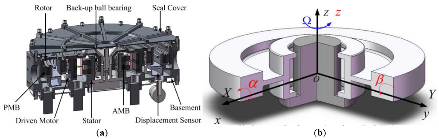
(a) The sketch of the hybrid MSFW system. (b) The rotor coordinate of the hybrid MSFW rotor.
The coordinate and motions with variable terms [x y z αβΩ] on six DOFs of the hybrid MSFW rotor are shown in Figure 1(b). The rotational speed Ω around Z axis is controlled by the PMSM. The radial translations with displacement variables x and y are controlled by the permanent magnet biased AMB and affected by the PMB. The radial rotations (rotational angle α around X axis and rotational angle β around Y axis) and the translation in Z axis (displacement term z) are passively controlled by the PMB when the hybrid MSFW rotor is suspended at the radial equilibrium position. Due to only two DOFs in radial translations are controlled by the permanent magnet biased AMB, the dynamic model and the control model in two controllable DOFs are developed, and the radial rotation of the hybrid MSFW rotor are analyzed according to the stiffness characteristics and magnetic torques of the PMB.
Model of hybrid MSFW
Magnetic force of permanent magnet biased AMB
Because the magnetic fluxes generated by the permanent magnet biased AMB and the PMB are not interlinked in the ferromagnetic steel embedded in the hybrid MSFW rotor, the magnetic forces generated by the permanent magnet biased AMB and the PMB could be calculated independently. For the permanent magnet biased AMB as shown in Figure 2(a), the magnetic forces acting on the hybrid MSFW rotor are generated by the magnetic fluxes of the bias PM ring and the coil currents in X+, X–, Y+, and Y– directions. When the hybrid MSFW rotor suspends at the radial equilibrium position, the magnetic flux densities in four airgaps of the bias PM ring are identical, so the resultant magnetic forces of the bias PM ring acting on the hybrid MSFW rotor is zero. When the hybrid MSFW rotor deflects from the radial equilibrium position, the magnetic flux densities in four airgaps of the bias PM ring would be different, so the resultant magnetic forces of the bias PM ring acting on hybrid MSFW rotor is not zero. Therefore, the coil currents are tuned to balance magnetic flux densities in airgaps along four directions, and then magnetic forces make the hybrid MSFW rotor back to the equilibrium position.

(a) The structure of permanent magnet biased AMB. (b) The equivalent magnetic circuit.
The equivalent magnetic circuit of the permanent magnet biased AMB is illustrated in Figure 2(b), the magnetic flux passes the ferromagnetic steel and airgap, finally returns to magnet pole. The coil currents in X+ and X– directions are equal and opposite. According to the Biot-Savart law, 26 the magnetic forces fex and fey in X and Y axes are respectively expressed into
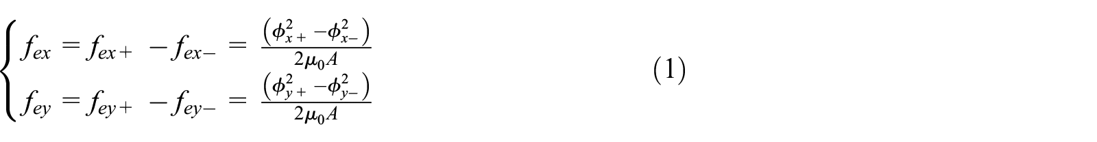
where fex+, fex–, fey+ and fey– are magnetic forces generated by permanent magnet biased AMB. A is the cross-sectional area of single magnet pole. µ0 is the vacuum permeability. φx+, φx–, φy+ and φy– are magnetic flux densities along X+, X–, Y+ and Y– directions, and

where Gpm is the magnetic conductance of the bias PM ring, Fpm is the magnetic potential of the bias PM ring, and they are

where Hc is the coercive force of the bias PM ring. Apm is the cross-sectional area of the bias PM ring. hpm is the length of the bias PM ring along the magnetization direction. µr is the relative vacuum permeability. ix and iy are control currents. N is the number of turns of single winding. g is the bias airgap of the bias PM ring. The length of the bias PM ring along the magnetization direction is 5 mm, and the maximum airgap of the bias PM ring is 0.3 mm, so there is

And then

The magnetic conductance in four airgaps are

The magnetic forces could be expressed into
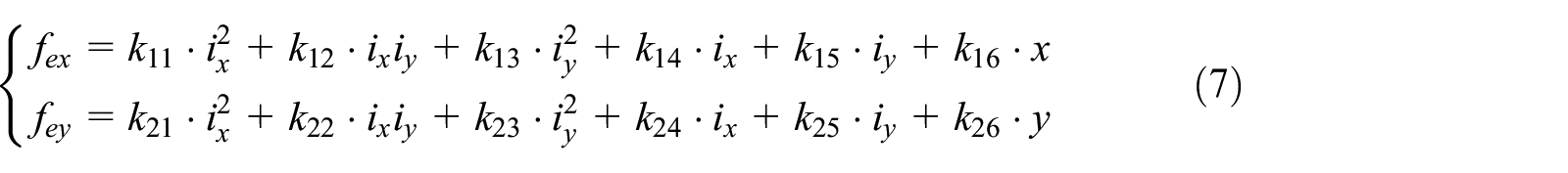
where k11∼k16 are coefficients of magnetic force fex, and k21∼k26 are coefficients of magnetic force fey.
Those coefficients (k11∼k16) of magnetic force are variable with radial displacements of the hybrid MSFW rotor. Considering the radial symmetry of the permanent magnet biased AMB, the coefficients of magnetic force fex are chosen as example, and relationships among coefficients k11∼k16 and radial displacements are presented in Figure 3. The second-order coefficients (k11, k12, and k13) are much less than the first-order coefficients (k14, k15, and k16) with small control currents, so the second-order coefficients (k11, k12, and k13) could be neglected in the dynamic model of the hybrid MSFW rotor. So, the magnetic forces fex and fey along X and Y axes are respectively expressed into


The relationships among coefficients k11~k16 of magnetic force fex, displacement deflection in X and Y axis. (a) Coefficient k11. (b) Coefficient k12. (c) Coefficient k13. (d) Coefficient k14. (e) Coefficient k15. (f) Coefficient k16.
Magnetic force of PMB
As shown in Figure 4(a), the PMB consists of one PM stator ring and one PM rotor ring with axial magnetization. Since that the angle range of radial rotation caused by the PMB is small, the coupling between radial translations and radial rotations could be neglected. The axial translation of the hybrid MSFW rotor is determined by the component of gravity along Z axis, so the hybrid MSFW rotor would deflect from the axial equilibrium point when the component of gravity along Z axis is not zero, the magnetic force of the PMB could be further affected by axial displacement deflection. The magnetic force of the PMB 27 could be written into

where Qs and Qr are magnetic charges of two PM rings, respectively, and


(a) The structure of the PMB. (b) The coordinate of the PMB. (c) The displacement variation of the PMB.
The direction of magnetic force fpr is consistent with the angle θ, and the amplitude of magnetic force fpr is determined by the radius r and affected by the axial displacement deflection. The magnetic forces fpx and fpy in X and Y axes are respectively

Since the PMB is symmetric about axial axis, the eccentricity of two PM rings is

where σ* is magnet pole surface density, rin1 is the inside radius of PM stator ring, rin2 is the inside radius of PM rotor ring, rout1 is the external radius of PM stator ring, rout2 is the external radius of PM rotor ring. The geometric relationship in Figure 4(c) is obtained as following

The curve of the magnetic force fpr versus the radial displacement r is plotted in Figure 5(a) when the axial displacement varies from −1.8 mm to 1.8 mm. The eccentricity of two PM rings is less than 0.2 mm because of restriction of auxiliary backup ball bearing, so the magnetic force of the PMB could be expressed into a linear function with the displacement stiffness kpr and the axial displacement z as following

where kpr0 is the radial stiffness of the PMB when the axial displacement z is zero.

(a) Magnetic force of the PMB versus radial displacement. (b) Stiffness of the PMB versus radial displacement.
As shown in Figure 5(b), the linearized magnetic forces of the PMB in radial directions are

When the hybrid MSFW system works in space, the micro-gravity environment ensures the MSFW rotor suspends at the axial equilibrium position without axial displacement deflection, the displacement stiffness of the PMB kpr could be kept at a constant. For the experiment on the ground, the axial displacement is steady because of the fixed direction of the hybrid MSFW, so kpr could be regarded as a constant referring to (15).
Dynamic model of hybrid MSFW rotor in two active DOFs
In Figure 1(b), dynamic equations of the hybrid MSFW rotor in two controllable DOFs are

where Δfx and Δfy are disturbance forces, and m is the mass of the hybrid MSFW rotor.
The state variables are chosen as X = [x1x2x3x4]T = [x x′ y y′]T. The system inputs are control currents
where


Dynamic model of hybrid MSFW rotor in two passive DOFs
The rotational angles [αβ] around radial axes of the hybrid MSFW rotor are dominated by the PMB only, so the rotational stability around radial axes is determined by the torque stiffness of the PMB, the range of rotational angle α is [−1.2°, 1.2°] because of the limitation of backup ball bearing. Taking the rotation around X axis in Figure 6 for example. The PMB generates magnetic torque px when the hybrid MSFW rotor tilts an angle α around the equilibrium position. The calculation results of the magnetic torque px and the torque stiffness kpx are plotted in Figure 7, and the magnetic torque of the PMB has the restoring ability. When the hybrid MSFW rotor deflects from the radial equilibrium position, it could be pulled back to the equilibrium position by the magnetic torque with a negative stiffness. Therefore, the radial rotations of hybrid MSFW rotor are naturally stable.

Radial rotation of the PMB around x axis.

(a) The magnetic force of the PMB versus the radial displacement. (b) The torque stiffness of the PMB versus the radial displacement.
In the meanwhile, the radial rotations of hybrid MSFW rotor are affected by disturbance torques, and the primary disturbance in radial rotation is the residual couple unbalance. Due to the great torque stiffness of the PMB, the radial rotational angles of hybrid MSFW rotor are small at high rotational speed. As shown in Figure 8, the measured result of radial rotational angle is smaller than 0.02° when rotational speed is 5000 rpm. Therefore, the dynamic equations of radial translations could be decoupled from radial rotations, and influences acting on radial translation could be neglected.

The radial rotational angles of the hybrid MSFW rotor at the rated speed 5000 rpm.
State feedback exact linearization of hybrid MSFW rotor
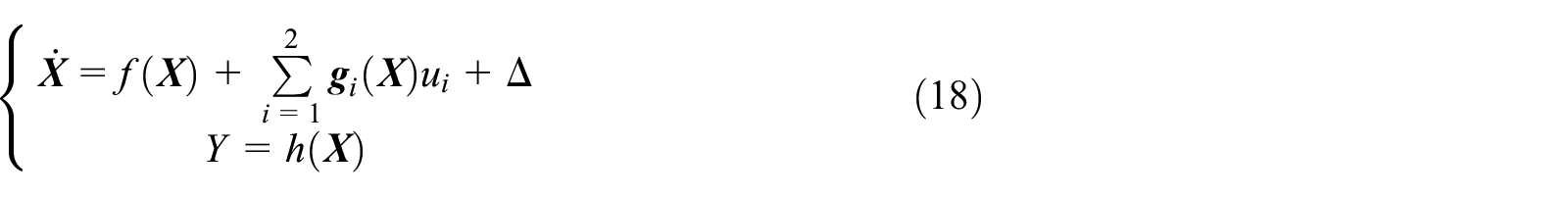
The nonlinear model of the hybrid MSFW rotor in (18) is the conical form, so it could be linearized exactly to a linear model through the state feedback.28,29 The dynamic function of the hybrid MSFW rotor in (18) is a four-order affine nonlinear system with two inputs and two outputs, so its relative degree defined by the Lie-derivative is four within the vicinity of
Since the relative degree of nonlinear model is four, the matrix

Defining the matrix as

And following inputs are introduced into the nonlinear model

The nonlinear model could be transformed into a linear model with a standard Brunovsky form

with state variables

So real inputs applied to the original nonlinear model are

Therefore, the SEFL model of the hybrid MSFW rotor has two signal input signal output (SISO) linear sub-systems.
Optimal control based on SFEL model of hybrid MSFW rotor
The control system designed for the hybrid MSFW rotor is illustrated in Figure 9. The optimal linear quadratic control is used to decouple the nonlinear model of the hybrid MSFW rotor. The measured displacements x and y are used as state variables. The cost function in (28) is chosen to evaluate the dynamic performance of the hybrid MSFW rotor.

where

Control diagram of nonlinear hybrid MSFW rotor.
Substituting (27) into

It is obvious that (29) is nonlinear about the displacement of hybrid MSFW rotor, so the linear matrix of the cost function through Taylor series is achieved as following

where


Substituting (30) into (28), the constant cost function for optimal control of linear model is

where

The matrix

Substituting (35) into (27), the feedback law for nonlinear model of the hybrid MSFW rotor is

Numerical simulation and experiment
Magnetic force of permanent magnet biased AMB
The hybrid MSFW rotor is not perfectly symmetric about mass distribution and geometry, so the unbalance term is not eliminated. When the hybrid MSFW rotor works at a high rotational speed, the periodical disturbance induced by the residual imbalance could affect the stability of the hybrid MSFW rotor. The disturbance forces caused by the static imbalance mass are

where R is the radius of the hybrid MSFW rotor, ms is the static imbalance mass of the hybrid MSFW rotor, αs is the location of imbalance mass, and ω is the rotational speed. The hybrid MSFW in the simulation and experiment is a prototype used in the attitude control of a middle-size satellite, and parameters are listed in Table 1. The angular moment of the hybrid MSFW is 25 Nm at 5000 rpm. The matrix

Parameters of hybrid MSFW rotor.

And the closed-loop poles are λ1,2 = −137.8±121.6
The feedback law applied to the SFEL model calculated from (35) is

Substituting the feedback law into (27), the actual inputs applied to the hybrid MSFW rotor are updated according to the system states.
In the simulation and experiment, the control performances of the PID control based on TL model and the optimal control based on SFEL model are compared. The initial states are

(a) The suspension traces of hybrid MSFW rotor. (b) The control currents of nonlinear and linearized model.
The suspension traces of the hybrid MSFW rotor with a periodic disturbance and an impulse disturbance are plotted in Figure 11. For the suspension traces of PID control based on TL model as shown in Figure 11(a), the settling time for the periodic disturbance is 150 ms, and the settling time for the impulse disturbance is 15 ms with 50 μm amplitude. As illustrated in Figure 11(b), for the optimal control based on SFEL model, the settling time for the periodic disturbance is reduced to 30 ms, and the settling time for the impulse disturbance is 5 ms with 45 μm amplitude. Therefore, the simulation results show that the optimal control based on SFEL model has better anti-disturbance performance than the PID control based on TL model.
The suspension traces of hybrid MSFW rotor with periodic disturbance and impulse disturbances. (a) PID control based on TL model. (b) Optimal control based on SFEL model.
Experiment
The protype of the hybrid MSFW with the permanent magnet biased AMB and the PMB is shown in Figure 12. The displacement sensors, winding of the permanent magnet biased AMB, PM stator ring of the PMB and windings of PMSM are mounted on the stator part of hybrid MSFW in Figure 12(b). The rotor part including the PM rotor ring and the hybrid MSFW rotor is shown in Figure 12(c). The whole experimental setup is displayed in Figure 13, the hybrid MSFW is sealed in a vacuum tank (pressure <5 Pa) to eliminate the influence caused by the wind drag at a high rotational speed. The main control unit (MCU) based on a DSP chip and a FPGA chip could realize the control method programming and collect system signals such as dynamic displacements, control currents and rotational speed. The oscilloscope timely records and displays the dynamic displacements of the hybrid MSFW rotor.

The protype of hybrid MSFW. (a) Full view. (b) Stator part. (c) Rotor part. (d) MCU.

Control diagram of the hybrid MSFW rotor.
The initial displacement of the hybrid MSFW rotor sets at X = [−200 μm 0 0 0], the suspension trace of the hybrid MSFW rotor with PID control based on TL model is plotted in Figure 14(a), and the suspension trace of the hybrid MSFW rotor with optimal control based on SFEL model is illustrated in Figure 14(b). The overshoot of suspension trace is reduced from 150 μm to 130 μm, and the settling time is declined from 145 ms to 65 ms by using the optimal control based on SFEL model. In the meanwhile, the suspension trace of the hybrid MSFW rotor along Y axis is affected by the suspension process along X axis, and the oscillation peak is reduced from 90 μm of PID control based on TL model to 30 μm of the optimal control based on SFEL model. Therefore, the optimal control based on SFEL model not only has better dynamic performance, but also minimize the coupling between suspension traces along X and Y axes.

Suspension traces of the hybrid MSFW rotor. (a) With PID control based on TL model. (b) With optimal control based on SFEL model.
Moreover, the dynamic displacements of the hybrid MSFW rotor at 5000 rpm are plotted in Figure 15(a), the dynamic displacement of the hybrid MSFW rotor with PID control based on TL model is shown by the blue line, and dynamic displacement with optimal control based on SFEL model is marked by red line. The displacement runout (peak to peak value) of the hybrid MSFW rotor is used to evaluate the control performance, the smaller displacement runout, the better control performance. The displacement runout of the hybrid MSFW rotor is 55 μm with the optimal control based on SFEL model, but that of PID control based on TL model is 100 μm. Figure 15(b) shows control currents ix and iy in control channels of X and Y axes when the hybrid MSFW rotor works at 5000 rpm. By applying the optimal control based on SFEL model, the control current (peak to peak value) is reduced from 0.18 A to 0.12 A. Therefore, the optimal control based on SFEL model has better performance on suppressing the displacement runout of the hybrid MSFW rotor at rated speed.

(a) Dynamic displacements of the hybrid MSFW rotor in X and Y axes at 5000 rpm. (b) Control currents ix and iy at 5000 rpm.
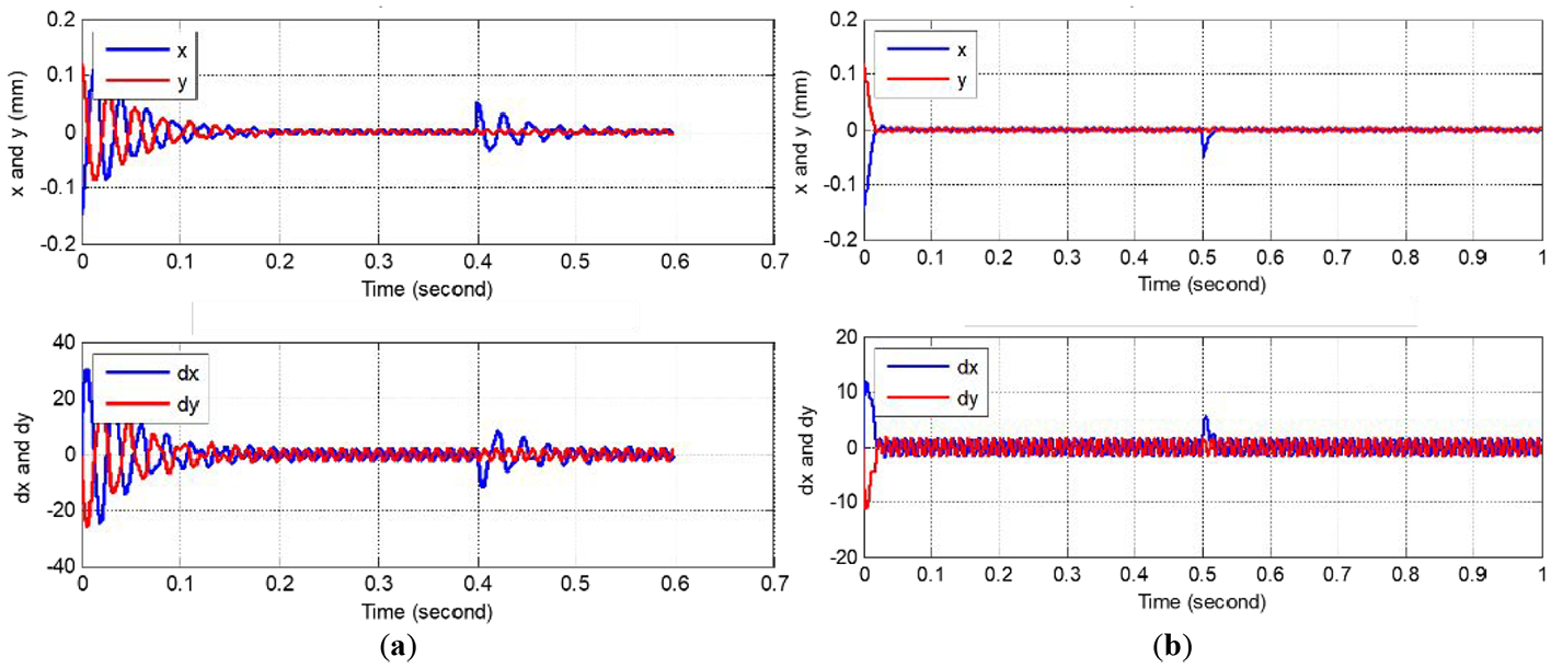
Referring to (7), there are coupling terms among dynamic equations of the hybrid MSFW rotor in different DOFs, so the disturbance acting on the suspension trace in Y axis also affects the dynamic displacements in X axis. The optimal control based on SFEL model is designed to minimize the coupling among two controllable DOFs of the hybrid MSFW rotor. The decoupling ability of the optimal control based on SFEL model and PID control based on TL model are compared when an impulse-type disturbance is imposed on suspension trace in X axis of the hybrid MSFW rotor at 5000 rpm. As illustrated in Figure 16, the dynamic displacement in X axis is obviously affected by the disturbance in Y axis, and both of two control models could stabilize dynamic displacements of the hybrid MSFW rotor. For the PID control based on TL model, the displacement runout along X axis is 340 μm, the settling time back to the equilibrium position is 45 ms. The displacement runout along X axis is declined to 40 μm and the settling time is shortened to 28 ms by applying the optimal control based on SFEL model. Therefore, this result is consistent with simulation result that the optimal control based on SFEL model has better decoupling ability and anti-disturbance ability than the PID control based on TL model.

(a) Decoupling ability of optimal control based on SFEL model. (b) Decoupling ability of PID control based on TL model.
Conclusion
In this article, the nonlinear dynamic model of the hybrid MSFW rotor with the permanent magnet biased AMB and the PMB is developed, and then there are coupling terms in two controllable DOFs. Furthermore, an optimal control strategy based on SFEL model is designed to improve the decoupling ability in two controllable DOFs and enhance the anti-disturbance ability of the hybrid MSFW rotor. As listed in Table 2, the simulation and experimental results prove that the optimal control based on SEFL model has better performance on decoupling and anti-disturbance when an impulse-style disturbance is imposed on the hybrid MSFW rotor at rated speed. Therefore, this control method is potential to be applied in control engineering of the hybrid MSFW used in attitude control of a middle-sized satellite.
Comparison between SFEL model and TL model.

Footnotes
Declaration of conflicting interests
The author(s) declared no potential conflicts of interest with respect to the research, authorship, and/or publication of this article.
Funding
The author(s) received no financial support for the research, authorship, and/or publication of this article.