
Abstract
Current power networks face considerable issues due to a continuous decrease in inertia and increased sensitivity to load/generation fluctuations. The main cause of these problems is the enhanced penetration capabilities of renewable energy sources. An unbalanced load with high power output greatly affects the frequency behavior of electrical grids. Several load-frequency control mechanisms are commonly employed to tackle these problems. Accordingly, the purpose of this work is to present a novel optimal load frequency control methodology for dual-area-linked power systems that contain a variety of conventional (i.e. thermal generator) and renewable (i.e. solar photovoltaic plant) power sources. A revolutionary hybrid regulator, the one plus proportional integral double-integral derivative with a proportional fractional derivative with fractional filter (1 + PIID-PDμFλ), has been designed. Its goal is to lessen frequency drifts brought on by any known load disturbance. The optimal gains of the 1 + PIID-PDμFλ controller are finely adjusted using the mother optimization algorithm, an up-to-date population-based metaheuristic optimization technique that simulates the procedure of birthing and growth. The mother optimization algorithm has demonstrated its superior performance compared to other brand-new optimization methods, including tuna swarm optimization and sea horse optimization. The effectiveness of the proposed mother optimization algorithm-based 1 + PIID-PDμFλ regulator is assessed by comparing its performance with other cascaded regulators in existing literature, such as TIDF-PIDμD, FOPI-PIDA, and PID-TID, which stand for tilt integral derivative with filter-proportional integral derivative fractional derivative with filter, proportional integral-proportional integral derivative acceleration, and proportional integral derivative-tilted integral derivative, respectively. Various scenarios involving fluctuations in load (step, multi-step, and random), solar radiation changes, and system parameter modifications are used to demonstrate the controller's effectiveness in handling disturbances. The simulation results, presented using MATLAB/SIMULINK, show that the proposed controller outperforms other existing controllers in terms of its dynamic response to system disturbances, namely it achieved a substantial reduction in frequency overshoot (94.66%, 48.49%, 68.75%), undershoot (94.66%, 26.75%, 67.25%), and settling time (78.57%, 90.81%, 75.0%) as measured by the frequency deviation in Area 1, respectively. Similar improvements were observed in frequency deviation in Area 2 and deviation in power exchange between system areas.
Keywords
Introduction
Background
Modern power systems, characterized by a diverse mix of conventional and renewable energy sources (RESs), are evolving rapidly. The integration of RESs such as wind and solar power, while offering significant environmental and economic benefits, introduces new challenges to system stability and security. The economic benefits of integrating RESs like wind and solar into newly developed power systems are substantial, as they help decrease reliance on oil, coal, and gas for traditional power generation. This shift is crucial, as burning fossil fuels contributes to carbon dioxide emissions, leading to global warming and worsening ozone depletion. While the introduction of RESs lowers operating costs and reduces pollution from conventional power plants, these sources also lack system inertia, which can compromise stability and lead to greater frequency fluctuations.1,2 Consequently, alongside the ongoing challenge of aligning supply with demand, the integration of RESs introduces additional complexities that threaten the stability and security of the power grid. 3 To address these challenges and ensure the seamless integration of RESs, advanced control techniques are required. These techniques must be capable of effectively mitigating frequency deviations, maintaining power balance, and enhancing the overall system resilience. By effectively managing system frequency, LFC plays a crucial role in ensuring the reliable and efficient operation of modern power systems.
Literature review
For load frequency control (LFC), numerous controllers have been proposed, as described in references.4–6 These controllers use a variety of methods, including integer-order, predictive, fuzzy logic, neural network, and fractional-order (FO) systems, as well as more advanced control designs. Additionally, the literature discusses various LFC systems that combine tilt, derivative, proportional, integral, and filtered derivative components. Researchers have focused on the conventional PID controller due to its simplicity and cost-effectiveness. However, this controller struggles to adapt its settings through trial and error when faced with system nonlinearities and disturbances. The optimization of PID controller settings has thus been the focus of a great deal of work. As mentioned in references,7,8 optimization techniques have been applied to enhance the design of PID controllers for LFC. In contrast, FO controllers have become more popular due to their flexibility and additional degrees of freedom. One type of FO controller that has been employed to solve LFC issues is the tilted integral derivative (TID) controller. TID controllers offer advantages such as easier tuning, improved disturbance rejection, and reduced impact on the plant. As a result, TID controllers have been proposed as alternatives for LFC issues in multiple studies.9–11 Additionally, references12,13 introduce a composite controller that integrates TID and FOPID controllers, taking advantage of the benefits of both approaches, such as easier tuning, improved disturbance rejection, and minimal impact on the system. In their analysis of power networks, 14 integrated the settings of the proportional-integral controller and the tilted derivative controller with filter. 15 Introduced a FOPTID+1 controller for Automatic Generation Control (AGC) in multi-source power systems, optimized using the global neighborhood algorithm (GNA). Its performance was evaluated under both linear and nonlinear conditions, with capacitive energy storage (CES) further enhancing system stability during load disturbances. 16 introduced an enhanced FO frequency controller utilizing a design optimization process. This controller has two cascaded control loops, utilizing a one-plus-proportional derivative (1 + PD) in the outer loop and a FO proportional integral derivative (FOPID) in the inner loop. This controller has demonstrated its efficacy in a hybrid dual-area power grid by exhibiting a rapid response time with reduced overshoot and undershoot peaks, as well as the capacity to mitigate both high- and low-frequency disturbances. Furthermore, the controller parameters are optimized with the Manta Ray Foraging Optimization (MRFO) methodology.
The combined approach described in reference. 17 utilized a refined genetic algorithm (GA) and particle swarm optimization to create a controller intended to maintain stable frequency in power networks.
Recently, the cascaded controller design has risen in popularity over traditional designs because of its effectiveness and improved performance. In order to improve frequency stability in power systems, a variety of cascaded controller types have been employed.18–21 Additionally, recent research in LFC has explored the approach of integrating two controllers.22,23 A fractional order cascade controller, including a fractional order proportional-integral controller cascaded with a fractional order tilt-derivative controller (FOPI-TDμ), is presented as the secondary frequency regulator in reference. 24 The proposed FOPI-TDμ controller exhibits more flexibility and adaptability compared to integer order controllers, hence enhancing the efficiency of the control system. The tunable parameters of the suggested regulator are optimized using the Kidney Algorithm. A virtual inertia-equipped energy storage system is utilized to enhance system inertia. The suggested controller's efficiency is evaluated against PID, TID, and FOPID controllers within a single area microgrid under various disturbances and operational situations. 10 presented a novel integrated three degree of freedom proportional integral derivative (3DOF-PID) and tilted-integral (TI) regulators to improve system performance, robustness, and frequency response in a power grid. The enhanced efficacy of the proposed 3DOF-PID-TI has been validated through a comparative analysis with three other controller designs (FOPID, PDPID2, and 2DOF-PID) for the multi-source shipboard microgrid system. The study also examined the temporary delays caused by the communication connections between the sensor and the regulator. The Triangulation Topology Aggregation Optimizer, a novel meta-heuristic method, was utilized for setting the controllers’ gains.
To regulate frequency in power networks with two separate regions, researchers have combined FO proportional-integral-derivative controllers and fuzzy logic controllers, as described in reference. 25 In reference, 26 a hybrid optimization method combining the gravitational search strategy and the firefly method was introduced to optimize the settings of the regulator for a two-area hydrothermal power grid. 27 optimized the gains of a fuzzy PID controller, which included a filter for the derivative action, using the Bees Algorithm (BA). This control method was applied to a multi-region interconnected power grid. In reference, 28 a new type of fuzzy PID controller called a type two fuzzy PID (T2-FPID) regulator was implemented in a multi-area power grid. The controller's performance was evaluated under various operating conditions, including load disturbances, generation rate constraints, and communication time delays. The parameters of this controller were optimized using the Water Cycle Approach (WCA). 29 introduced a Fuzzy Tilted Fractional Order Integral Derivative with Fractional Filter (FTFOIDFF) as a load frequency regulator. The FTFOIDFF regulator integrates the advantages of tilt, fuzzy logic, FOPID, and fractional filter regulators. Moreover, the Prairie Dog Optimizer (PDO), a revolutionary metaheuristic optimization method, effectively calibrates the proposed controller parameters and the shapes of the fuzzy logic membership functions in the dual-region hybrid electrical system examined in the study. The system model includes physical limitations, like communication time delays and generation rate restrictions. A unified power flow controller is installed on the tie-line, and superconducting magnetic energy storage devices are proposed for both regions, alongside electric vehicles. Reference 30 explored using an arithmetic optimization approach to fine-tune a fuzzy PID regulator, taking into account how high-voltage direct current lines can help solve the problems related to the AC links.
Research gap and motivation
LFC is a critical function in power systems, responsible for maintaining system frequency and power balance, ensuring reliable operation during disturbances.31,32 Traditionally, LFC has relied on conventional power plants, such as thermal and hydropower plants, which possess inherent inertia to regulate frequency, utilizing two control loops: primary and secondary for LFC. However, the rapid adoption of RESs has been driven by the need to reduce air pollution and address economic challenges related to fuel costs. As a result, renewable generation systems need to be adapted to support LFC efforts. 33 Among these renewable sources, photovoltaic (PV) systems require particular focus for their potential contribution to LFC. To address the challenges to power system stability due to the intermittent nature of PV systems and lack of inherent inertia, innovative control strategies are necessary to enable PV systems to actively participate in LFC. Although existing research has identified effective approaches for LFC in power systems, the specific algorithms suitable for PV systems are still relatively limited. Notably, solar PV systems are distinguished by their environmentally friendly nature, widespread availability, and abundance, warranting further research to enhance their role in LFC. Large PV installations can significantly aid in frequency control during sunny periods when equipped with suitable control strategies.
A mathematical model for PV systems aimed at improving LFC has been presented in references.34,35 The authors of reference 36 proposed the Firefly Algorithm and GA to optimize the settings of a traditional controller for a PV plant in a two-area power system. Furthermore, studies in references37,38 have investigated the use of bio-inspired optimization algorithms and modified hill climbing techniques for similar purposes.
Key contributions
This study introduces a new hybrid controller, referred to as (1 + PIID-PD ✓ It employs a robust 1 + PIID-PD ✓ It proposes a novel and effective optimization method, the MOA, to optimize the parameters of the proposed 1 + PIID-PD ✓ Finally, it tests the controller's effectiveness and stability in the two-area PV-based interconnected power system under various disturbances, including load fluctuations (step, multi-step, and random), changes in solar radiation, and alterations in system parameters.
Organization of paper
The paper's remaining sections are organized as follows: The PV plant, thermal plant, and hybrid power system under study are all modeled in section “LFC system modeling.” The MOA and the 1 + PIID-PD
LFC system modeling
Frequency management in hybrid interconnected systems is becoming more important and difficult as the world moves away from traditional energy sources and toward green ones. Using green energy in power grids can cause problems with frequency control loops because they lower the system's inertia, which can make it less stable and cause frequency changes to happen more often. The system has been developed to minimize frequency deviations using the suggested 1 + PIID-PDμFλ controller for frequency regulation in a hybrid power network that incorporates both renewable (i.e. PV) and conventional (i.e. thermal) sources. The area control error (ACE) represents the measured output value for the LFC loop. The system analyzed in our study has been modeled using R2023b MATLAB Simulink on a computer equipped with an AMD Ryzen 7 3700U CPU operating at 2.3 GHz and 20GB of RAM. The following subsections present a comprehensive overview of the modeling approach.
Photovoltaic plant
A PV power plant, a large-scale assembly of interconnected solar cells, is a critical component of modern power grids. Unlike smaller residential or industrial PV systems, these plants are designed to inject significant amounts of electricity into the main power network. By virtue of their size and direct grid connection, PV plants play a vital role in providing ancillary services, such as frequency regulation, which are essential for grid stability. A PV plant is constructed by combining multiple solar cells into panels through series and parallel configurations to increase power output. To develop a comprehensive model of a PV system, it is necessary to begin at the fundamental level of a single solar cell. A solar cell can be represented as a p-n diode with a current source and a resistor. The current generated by the cell is directly influenced by solar irradiance and is also affected by ambient temperature. The circuit diagram of a solar cell is depicted in Figure 1. A comprehensive mathematical model of a PV plant is fully illustrated in references.34–38

Equivalent circuit diagram of a solar cell. 11
The performance of PV systems is inherently influenced by factors such as solar irradiance and ambient temperature. To accurately model the dynamic behavior of PV systems for LFC studies, a simplified transfer function model is commonly employed. This model captures the collective behavior of key components, including solar panels, maximum power point tracking systems, inverters, and output filters. As illustrated in Figure 2, the transfer function model described in references34–37 represents the relationship between changes in solar irradiance and temperature and the corresponding variations in PV power output. By introducing step changes in these input variables, the dynamic response of the PV system can be simulated, providing valuable insights into its impact on system frequency stability.
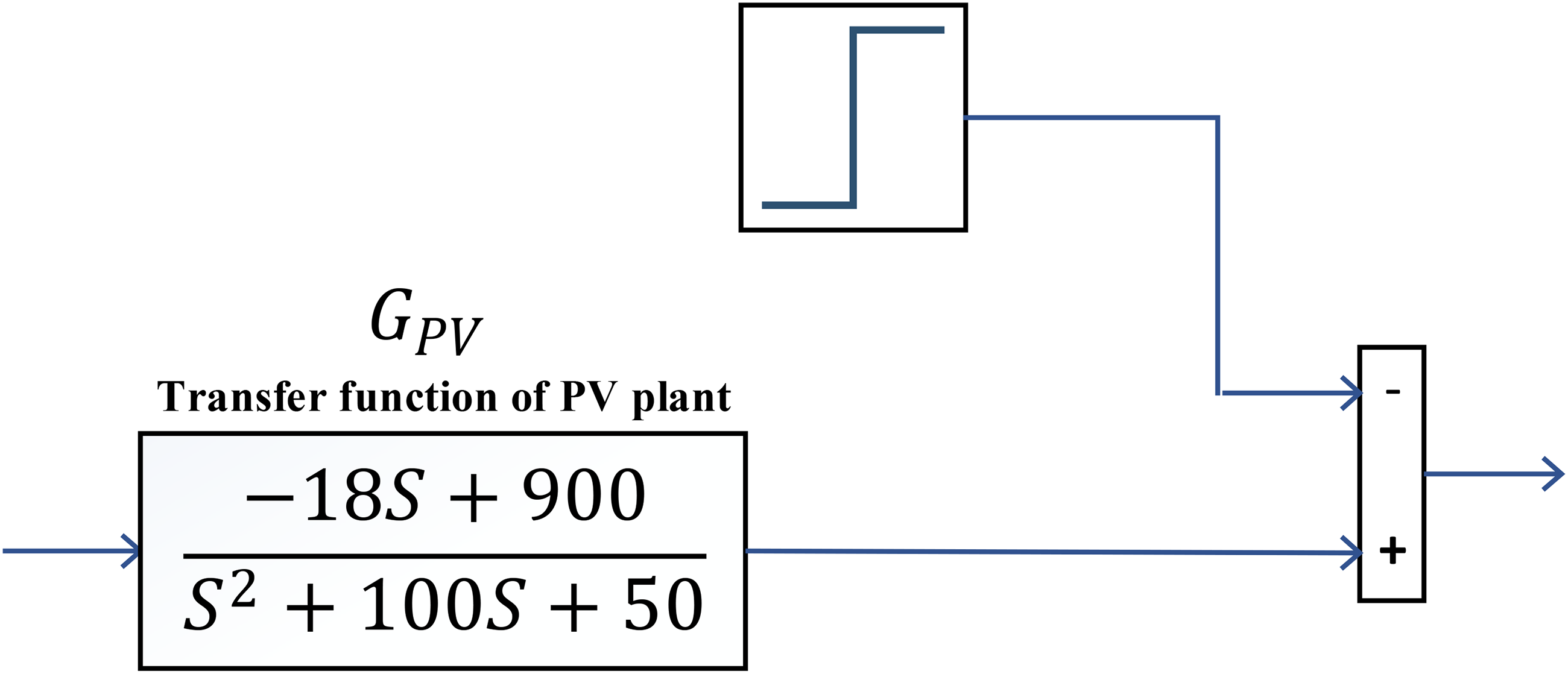
Transfer function model of the photovoltaic (PV) system. 38
Thermal power plant
To accurately simulate a thermal plant within the context of LFC, four primary components must be modeled: the generator itself, the steam turbine, the governor, and the reheater. 44 Figure 3 presents a transfer function model encompassing these components.

Transfer function model of the thermal power plant.
Thermal power plants incorporate two control loops to regulate frequency. The initial control loop, centered around the governor, provides an effective response to sudden frequency changes. While the primary control loop is effective in addressing short-term frequency deviations, it may not be able to completely eliminate persistent frequency errors. To address this, a secondary control loop is introduced, which utilizes the ACE signal as a corrective input. The ACE signal is a composite measure of the tie-line power deviation and frequency deviation, weighted by the area bias factor. By monitoring the ACE signal, the secondary control loop can identify and correct long-term frequency errors, ensuring the overall stability and reliability of the power system.
Mathematically, the ACE signal can be expressed as follows:

Herein,
Two-area hybrid power system
Figure 4 illustrates the Interconnected PV-thermal power system being investigated. As illustrated, the studied power system consists of two interconnected areas, each containing a distinct power generation source: a PV plant and a thermal power plant. Due to the independent controllers employed for each generation unit, each unit constitutes a separate control area. Detailed system parameters can be found in reference. 36 Power system frequency stability is inextricably tied to the delicate balance between power generation and load demand. Any deviation from this equilibrium can lead to frequency fluctuations that may compromise system reliability and security. In this system, load fluctuations, caused by the dynamic nature of load centers throughout the day, are considered a disturbance primarily affecting the thermal plant area. In addition to load fluctuations, variations in solar radiation, which affect the power output of the PV plant, are considered as another disturbance within the hybrid two-area power system. Figure 4 also shows the decentralized controllers. As depicted, separate control systems are used for the PV plant and the thermal plant, operating independently within their respective areas. These controllers receive data specific to their generation units and regulate output accordingly. The next section offers a more thorough examination of the decentralized control approach.

Interconnected PV-thermal power system understudy.
Control strategy and problem formulation
This section discusses the design of the cascaded 1 + PIID-PDμFλ controller, with parameters meticulously optimized using the recently introduced MOA to tackle the LFC problem. Research suggests that traditional integer controllers exhibit limitations in managing system uncertainties. Consequently, the proposed controller has excelled by including the flexibility of fractional order (FO) parameters, represented by PDμFλ, into the employed classical controller (i.e. 1 + PIID). The subsequent subsections include thorough details regarding the MOA and its application in tuning the parameters of the proposed 1 + PIID-PDμFλ controller, along with the configuration of the proposed controller.
Mother optimization algorithm
Inspiration and idea
The foundation of a child's education is undeniably the family, with the mother playing a pivotal role in their development. Mothers impart their life experiences and knowledge to their children, fostering the growth of their children's capabilities. The core of the mother–child relationship involves three key interactions: education, guidance, and nurturing. Inspired by these maternal behaviors, the MOA employs mathematical modeling to simulate and optimize problem-solving processes.
Mathematical representation of MOA
The MOA is a population-based optimization technique that iteratively improves a set of potential solutions to solve optimization problems. This group, or population, is composed of multiple solutions represented as data points within the problem's solution space. The population of candidate solutions is mathematically structured as a matrix, as defined by equation (2).
39
To initiate the optimization process, an initial population is generated using equation (3).
39
Each member of this population contributes to finding the best solution by exploring different areas of the problem space.


The equations represent the population matrix (
In MOA, each individual within the population represents a potential solution to the optimization problem at hand. To assess the performance of each solution, to evaluate how well each solution performs, it's necessary to calculate the objective function using the values assigned to the decision variables within that solution. This process results in a vector of objective function values, as depicted in equation (4).

Here, the vector containing the objective function values is denoted as F, and Fi denotes the objective function value for the ith candidate solution. The success of each potential solution is measured by its objective function value. The performance of each candidate solution is evaluated by its corresponding objective function value. By comparing these values, the algorithm identifies the best and worst-performing solutions within the population. Throughout the iterative process, the best solution is continuously tracked and updated as the algorithm progresses. Ultimately, the best solution found at the end of the process is considered the optimal solution to the optimization problem.
The MOA is designed to refine these potential solutions in three stages, mirroring the process of a mother raising a child. These stages will be detailed in the following section.
Phase 1: phase of education or exploration. The initial phase of the MOA, termed “Education,” mirrors the process of educating children. The goal is to broaden the search area for potential solutions by substantially modifying the existing solutions. The algorithm designates the best solution as the “mother” and models her influence on the other solutions in order to model the education process. This process involves updating the position of each solution using equation (5). If a new position results in an improved solution, as determined by the objective function, it replaces the old position, as shown in equation (6).
39


Here,
Phase 2: phase of advice or exploration. A crucial aspect of parenting is guiding children away from negative behaviors. This principle is incorporated into the MOA's second phase. This phase encourages exploration of the solution space by introducing substantial modifications to the population members. In MOA, solutions with poorer objective function values are identified as undesirable. These “bad” solutions are compiled into a set, (


The array of “bad behaviors” for the ith population member is denoted by
Phase 3: phase of exploitation and upbringing. Similar to how mothers nurture their children's growth, the “Upbringing” phase of MOA focuses on refining existing solutions through small adjustments. This phase enhances the algorithm's ability in local search and exploitation of the search space. To mimic child development, new potential solutions are generated based on equation (10). If these new solutions outperform their predecessors, they replace the original solutions equation (11).


Repetition process, and MOA flowchart. The MOA algorithm iteratively improves its potential solutions by cycling through the three distinct phases: education, advice, and upbringing. This process continues until a predetermined number of iterations is reached. Throughout this process, the algorithm maintains a record of the best solution found thus far. Once completed, the algorithm returns the best answer as the final result. A visual representation of the MOA process is provided in a flowchart (Figure 5).

Flowchart of MOA. 39
Structure of the controller
The proposed 1 + PIID-PD


Combined regulator control diagram.
In this analysis of the two-area power system understudy, both regions utilized the 1 + PIID-PDμFλ controller. The traditional PID controller has gained popularity among researchers due to its simple structure and efficient operation. The PIID controller is similar to the conventional PID controller but includes an additional second-order integral term. The 1 + PIID-PDμFλ controller was selected for this study as it combines the qualities of both linear controllers and fractional calculus by introducing FO derivatives and integrals into the PID structure, the 1 + PIID-PDμFλ controller gains several advantages including:
FO controllers can often achieve better performance than their integer-order counterparts, such as faster settling time, reduced overshoot, and enhanced robustness to disturbances and uncertainties. FO derivatives and integrals provide additional degrees of freedom in controller design, allowing for more precise tuning and adaptation to specific system dynamics.
The transfer functions for the 1 + PIID and PD

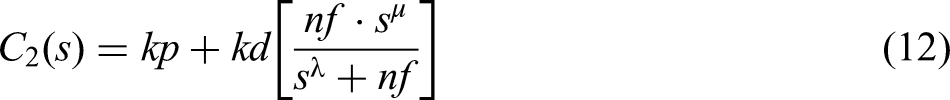
where (

The suggested 1 + PIID-PD
The MOA algorithm will be employed to determine the optimal parameter values for the 1 + PIID-PDμFλ controller by minimizing the fitness function (FF). The optimization process aims to minimize the integral time square error (ITSE), a performance metric that effectively reduces settling time and suppresses large oscillations.
43


Simulation results and analysis
This section assesses the performance of the two-area hybrid power system, under a variety of operating conditions. These conditions include diverse load disturbances (step, random, and multi-step), the integration of RESs, and variations in system parameters. The proposed 1+ PIID-PD
Assessing the effectiveness of MOA
In this section the effectiveness of the MOA is evaluated within the context of LFC studies. The performance and efficiency of the proposed MOA optimization technique are compared to other optimization methods in literature, including TSO 40 and SHO. 41 The primary objective of this comparison is to assess the ability of each optimization technique to optimize controller settings and improve the frequency stability of the two-area power system under study. The first area is subjected to 10% step load disturbance (SLD), the maximum number of iterations and population size is set to 100 and 30, respectively.
Consequently, Table 1 presents a summary of the optimal settings for the 1 + PIID-PD
Optimum settings of the proposed 1+PIID-PD
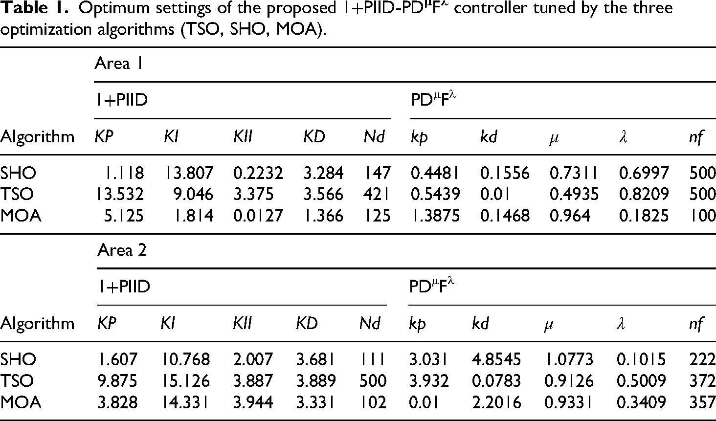
Figure 8 presents a comparison of the convergence curves for the three optimization algorithms: MOA, SHO, and TSO. It is evident that MOA exhibits superior convergence performance compared to both SHO and TSO. Figure 9 shows the dynamic response of the system in terms of (a) frequency deviation in Area-1 (ΔF1), (b) frequency deviation in Area-2 (ΔF2), and (c) tie-line power deviation (ΔPtie). It can be concluded that the proposed controller, tuned using the MOA algorithm, outperforms the SHO and TSO algorithms in terms of minimizing undershoot, overshoot, and settling time. The 1 + PIID-PD

The convergence curves for (MOA, SHO, TSO) optimization techniques.

Dynamic power system response: (a) ΔF1, (b) ΔF2, and (c) ΔPtie.
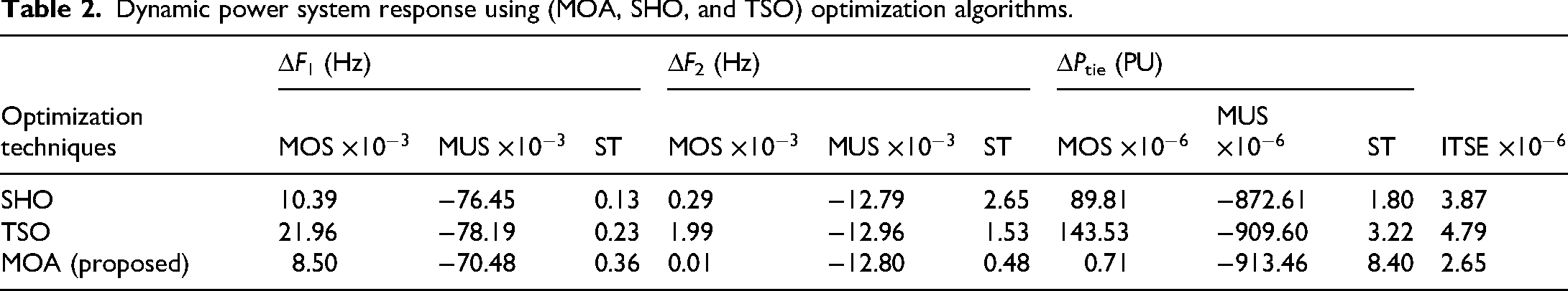
Table 2 provides a summary of the various controllers’ overall performance in terms of Maximum Overshoot (MOS), Maximum Undershoot (MUS), and Settling Time (ST) for the three shown system responses (i.e. ΔF1, ΔF2, and ΔPtie). Table 2 clearly indicates that MOA outperforms the other two methods, TSO and SHO, particularly in terms of MOS values across all system responses. For instance, the improvement percentage of MOA relative to TSO is 99.5% and relative to SHO is 96.6%, as measured by ΔF2.
Dynamic power system response using (MOA, SHO, and TSO) optimization algorithms.
Robustness analysis of the suggested 1 + PIID-PDμFλ controller
To validate the effectiveness of the proposed controller in enhancing the performance of the analyzed multi-source power system, a series of simulations were conducted using the MATLAB/Simulink environment. The simulation setup involved various scenarios, including different load disturbances and renewable energy integration. The simulation results are presented in the following subsections:
Scenario I: Assessment of the system's dynamic response to diverse load disturbances.
Scenario II: Assessment of the system's dynamic response to fluctuations in solar radiation. Scenario III: Evaluation of the system's sensitivity to changes in system parameters (Sensitivity Analysis).
Scenario I: assessment of the system's dynamic response to diverse load disturbances
This scenario involved subjecting the power system to a variety of load disturbances, including SLD, multi-step load disturbances (MSLD), and random load disturbances (RLD). All disturbances were introduced to the first area. This scenario is further divided into three subsections.
Section A: assessment of power system performance in response to 10% SLD. This subsection evaluates the performance of the power system in response to a 10% SLD applied to the first area. The focus is on assessing the system's ability to maintain stability and regulate frequency under this specific disturbance condition. In the power system, SLD can be represented by disconnecting specific generators, leading to power outages due to the complete shutdown of all generators at the power stations. Following the demonstration of MOA's superiority in section “Assessing the effectiveness of MOA,” MOA has been employed to optimize several present controllers, including FOPI-PIDA, 4 PID-TID, 43 TIDF-PIDμD, 42 and the proposed 1 + PIID-PDμFλ controller. The optimum controllers’ settings, displayed in Table 3, achieved in this scenario have been employed in the following scenarios. The performance efficiency of the proposed 1 + PIID-PDμFλ controller, optimized by the MOA, has been compared to that of other controllers to demonstrate the exceptional capabilities of the recommended regulator.
Optimal controller parameters (scenario I).

Figure 10 clearly shows that the suggested controller integration greatly improves the system's dynamic performance when compared to other control schemes in the literature. The suggested MOA-based 1 + PIID-PDμFλ controller reduces undershoot, overshoot, and settling time better than the other three control techniques.

Dynamic response of the power system to a step load disturbance (SLD) presented in scenario I, section A: (a) ΔF1, (b) ΔF2, and (c) ΔPtie.
Table 4 summarizes the key dynamics of system performance in this situation while employing the four comparable controllers. According to Table 4, the 1 + PIID-PDμFλ controller, optimized via the MOA algorithm, demonstrates the minimal overshoot (
Dynamic response of the power system to a step load disturbance (scenario I, section A).

Section B: assessment of Power System Performance in Response to MSLD. This subsection examines the system's response to a MSLD, which simulates realistic load variations in the two-area power system. Figure 11 illustrates the MSLD signal, which mimics sudden load changes or a sequence of generator outages. To assess the efficacy of the MOA-optimized 1 + PIID-PDμFλ controller, the first area was subjected to a series of load changes, and the outcomes were compared to various control strategies, including PID-TID, FOPI-PIDA, and TIDF-PIDμD controllers, all optimized using the MOA algorithm. Figure 12 display the dynamic system responses represented by (a) ΔF1, (b) ΔF2, and (c) ΔPtie, while Table 5 contains the dynamic response statistics for the understudy power system under the impact of MSLD. Conversely, the suggested 1 + PIID-PD

MSLD profile for scenario I, section B.

Dynamic response of the power system to a multi-step load disturbance (MSLD) presented in scenario I, section B: (a) ΔF1, (b) ΔF2, and (c) ΔPtie.
Dynamic response of the power system to a multi-step load disturbance (scenario I, section B).

Section C: assessment of the Power System Performance in Response to Random Load Disturbances (RLD). This subsection assesses the effectiveness of the proposed 1 + PIID-PD

RLD profile for scenario I, section C.

Dynamic response of the power system to Random Load Disturbance (RLD) introduced in scenario I, section C: (a) ΔF1, (b) ΔF2, and (c) ΔPtie.
Dynamic response of the power system to random load disturbance (scenario I, section C).

Scenario II: assessment of the system's dynamic response to fluctuations in solar radiation
This scenario evaluates the power system's performance under different solar irradiance conditions, reflecting the impact of solar power generation variability on grid stability. The scenario is divided into two subsections: the first examines the system's response to a step reduction in solar irradiance, while the second assesses its performance under 24-h Gaussian curve to mimic actual irradiance data.
Section A: assessment of the System's Dynamic Response to Step Change in Radiation. In this scenario, a 0.2 p.u step change is introduced to the solar radiation of the PV plant, resulting in a 0.2 p.u reduction in power generation from the PV plant. Figure 15 illustrates the deviations in frequency and tie-line power over a 30-s period. The suggested 1 + PIID-PD
Dynamic response of the power system in response to a step change in solar radiation introduced in scenario II, section A: (a) ΔF1, (b) ΔF2, and (c) ΔPtie.
Dynamic system response characteristics in scenario II, section A.

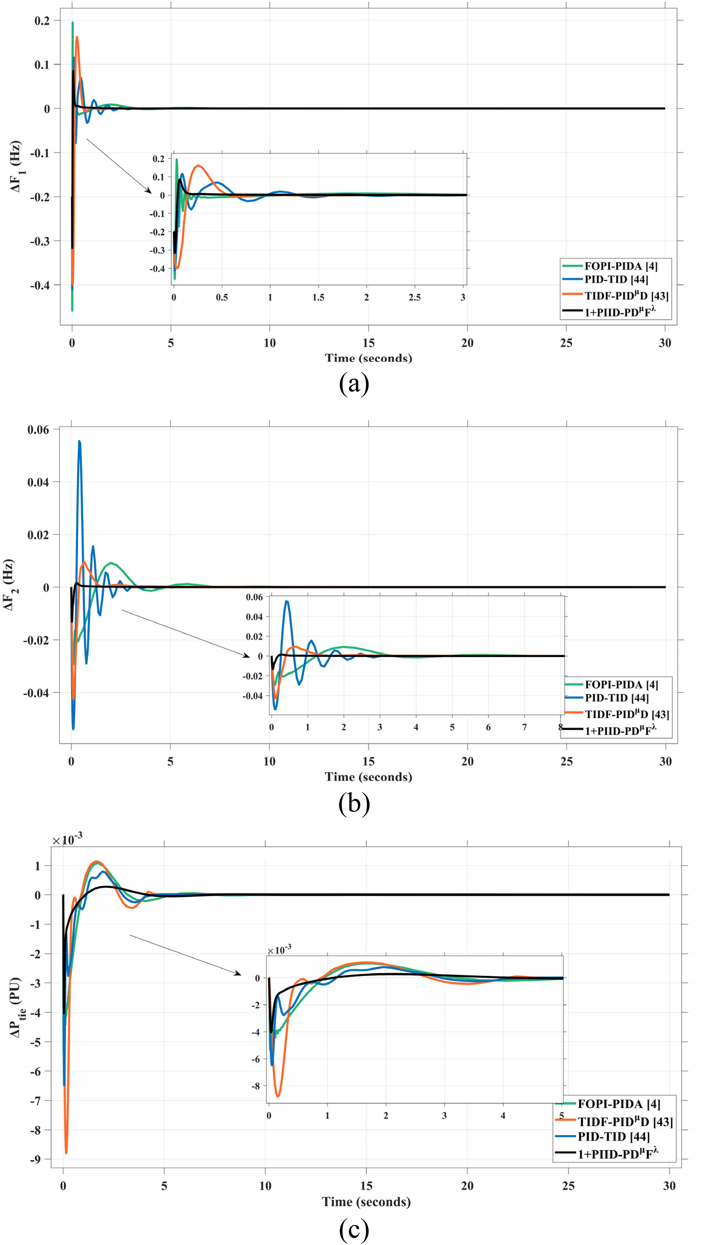
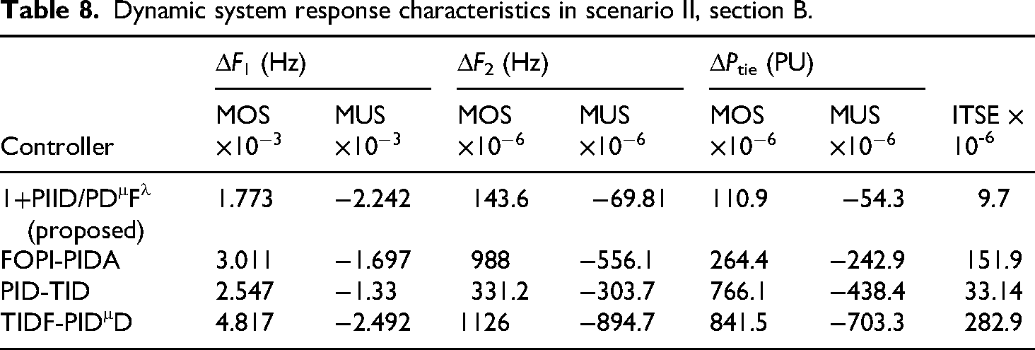
Section B: assessment of the system's dynamic response to realistic solar irradiance variations. In this scenario, the dynamic response of the power system is evaluated under realistic solar irradiance conditions, modeled using a 24-h Gaussian curve based on actual irradiance data. Figure 16 displays the solar irradiance signal profile. The solar generation profile reflects the natural variability of solar power output, which is influenced by factors such as time of day, cloud cover, and atmospheric conditions. The Gaussian curve represents a smooth transition from low to high irradiance during daylight hours, peaking at midday, and gradually decreasing towards sunset. This approach provides a more accurate representation of real-world solar power generation compared to simplified step changes. The proposed 1 + PIID-PDμFλ controller is tested under these realistic conditions to assess its ability to manage the inherent variability of solar power generation. The results, illustrated in Figure 17, demonstrate the controller's effectiveness in maintaining system stability and minimizing frequency deviations. The dynamic performance of the system under this realistic solar irradiance scenario is summarized in Table 8. From Table 8, one can clearly observe that the 1 + PIID-PDμFλ controller exhibits superior performance, specifically with ΔF2 response, which has a significantly reduced MOS (

Realistic solar irradiance profile for scenario II, section B.

Dynamic response of the power system in response to realistic solar irradiance introduced in scenario II, section B: (a) ΔF1, (b) ΔF2, and (c) ΔPtie.
Dynamic system response characteristics in scenario II, section B.
Scenario III: sensitivity analysis
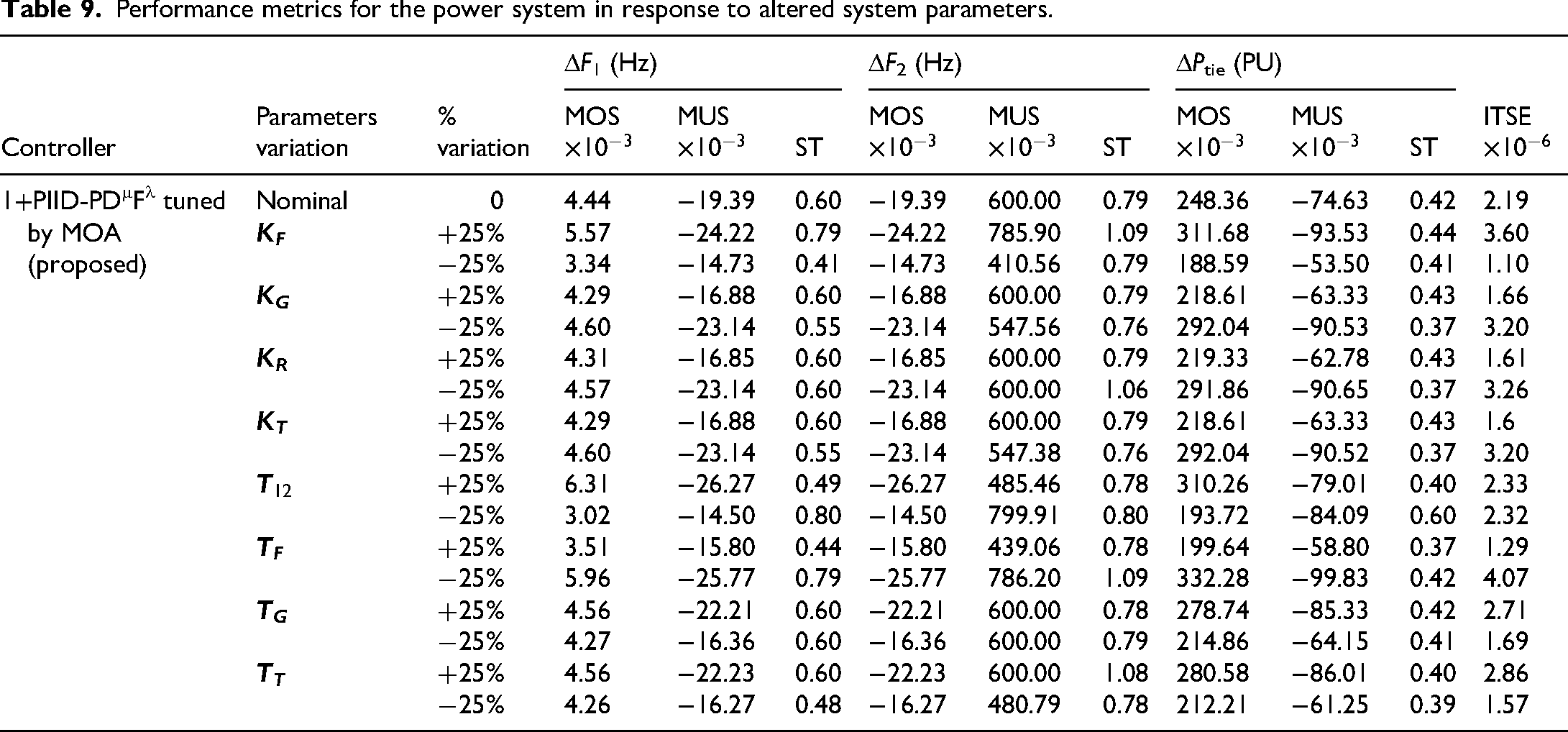
Sensitivity analysis assesses a system's ability to maintain its performance and stability in the face of variations in its parameters within a predefined range. This section evaluates the robustness of the power system by systematically varying key system parameters including
Performance metrics for the power system in response to altered system parameters.
In conclusion, in order to further validate the stability of the system that was analysed, taking into consideration the suggested 1 + PIID-PDμFλ control technique, a frequency response study has been conducted, which is depicted in the form of Bode plots, as seen in Figure 18. It is important to take note of the fact that the system is stable in a closed loop and has a large gain margin of 24 dB. This demonstrates that the system's stability has increased as a result of the control approach that has been provided.

Bode plot of the proposed 1 + PIID-PDμFλ control method.
Conclusion and future work
Modern power systems face significant challenges due to declining inertia and increased sensitivity to load and generation fluctuations, primarily caused by the growing integration of RESs. To address these issues, this paper proposed a novel 1 + PIID-PDμFλ controller designed to enhance frequency stability in hybrid power systems. The controller was evaluated in a system comprised of a thermal plant and PV plant. The suggested controller was implemented with TSO, SHO, and MOA algorithms to fine-tune its performance. The MOA algorithm was shown to provide improved performance with a faster response time. The effectiveness of the 1 + PIID-PDμFλ controller optimized using the MOA algorithm, was evaluated against the PID-TID, FOPI-PIDA, and TIDF-PIDμD controllers, which were also optimized using the MOA algorithm. Several scenarios were devised to examine the performance of the 1 + PIID-PDμFλ controller in regulating frequency and tie-line power in a two-area hybrid power system. The controller's effectiveness was evaluated under various scenarios, including step load changes, random load changes, and step changes in solar radiation. In each scenario, the controller demonstrated superior performance in regulating frequency and tie-line power deviations compared to the PID-TID, FOPI-PIDA, and TIDF-PIDμD MOA optimized controllers. The proposed hybrid 1 + PIID-PDμFλ controller demonstrated significant improvements in frequency stability control compared to PID-TID, FOPI-PIDA, and TIDF-PIDμD controllers. Notably, it achieved a substantial reduction in frequency overshoot (94.66%, 48.49%, 68.75%), undershoot (94.66%, 26.75%, 67.25%), and settling time (78.57%, 90.81%, 75.0%) as measured by ΔF1 respectively, similar improvements were observed in ΔF2 and ΔPtie. These results highlight its effectiveness in mitigating disturbances and maintaining system stability under dynamic conditions. A sensitivity analysis further validated the controller's robustness and adaptability across a wide range of system conditions. However, this controller may present certain challenges, including increased computational demands compared to simpler alternatives, difficulties in tuning due to the numerous parameters, and the possibility of not always surpassing the performance of “smart” controllers like fuzzy logic systems in all situations. To address these potential drawbacks, we can implement several mitigation strategies. These include utilizing faster processors for improved computational efficiency, employing advanced tuning algorithms to optimize parameter selection, and exploring hybrid approaches that combine the strengths of this controller with other control strategies, such as using fuzzy logic to refine the tuning of the 1 + PIID-PDμFλ controller parameters.
Future research should address the following areas: communication delays, expansion to multi-area systems, inclusion of additional renewables, and utilization of real-time simulators such as OPAL-RT or dSpace. By addressing these areas, future studies can further validate the controller's effectiveness and explore its potential applications in complex power systems.
Footnotes
Funding
The author(s) received no financial support for the research, authorship, and/or publication of this article.
Conflicting interests
The author(s) declared no potential conflicts of interest with respect to the research, authorship, and/or publication of this article.