
Abstract
The near-space solar-powered unmanned aerial vehicle has broad prospects in application owing to its high altitude long-endurance performance. Launching solar-powered unmanned aerial vehicle into the near-space with balloon-borne approach has advantages over the traditional sliding take-off methods, in that it is able to quickly and safely cross the turbulent zone. In this article, we investigate the control technology of balloon-borne launching for the solar-powered unmanned aerial vehicles. First, the motion of the launching process is divided into longitudinal and lateral-directional motion, with the longitudinal process and its equation addressed in detail. We then analyze the flight state and restriction conditions that the unmanned aerial vehicle should meet during the process. Second, the target variables and constraints are selected to formulate the optimization problem. The control variable parameterization method is applied to find the optimal pitch angle in the releasing-and-pulling process. More explicitly, a three-channel attitude stabilization controller is designed, in which the longitudinal channel takes the optimal pitch angle as the pitch instruction, the transverse channel carries out the zero control of the inclination angle, and the course channel takes the stabilization control, respectively. Numerical simulation results show that our proposed control design is capable of accelerating the solar-powered unmanned aerial vehicles from the vertical state and pulling them up to the horizontal cruising flight state, with the flight angle of attack, the maximum speed, and the maximum axial acceleration in the pulling process all within the designed range.
Keywords
Introduction
The near-space solar-powered unmanned aerial vehicles (SP-UAVs) harvest solar energy throughout the day, storing energy inside the energy storage batteries (such as lithium sulfur battery) and using the stored energy for night cruising. Having the advantages of high altitude long-endurance (HALE) performance, being less affected by the tropospheric weather, and multiple mission payloads, the SP-UAVs will play an increasingly important role in plenty of fields. 1 For civil use, the SP-UAVs are employed in geological resource surveys, weather forecasting, environmental warnings, signal relaying base station, and so on. In the military realm, the SP-UAVs can be developed for communication relays, reconnaissance, and early warning platform in near-space, which makes it possible to avoid the majority of attacks and signal interference, thus ensuring the effectiveness and accuracy of reconnaissance. Owing to its superiority, it is predictable that the SP-UAV platforms will have a very broad research prospect in the aviation field.
While there are many advantages, the SP-UAVs are also facing design difficulties. To improve the aerodynamic efficiency of the aircraft and to lay out large areas of solar panels, the SP-UAVs need to adopt the wing structure with a large aspect ratio, which have the characteristics of light weight, large wingspan size, and poor wind resistance. This poses challenges to the launching technology and payload capacity of the aircraft. Currently, most SP-UAV launchings adopt the sliding take-off method, which requires large thrust and takes a long time (Taking the climbing rate of 1 m/s as an example, it takes 6.95 h to climb to an altitude of 25 km) to complete the flight from ground sliding to the cruising altitude. Besides, in the climbing process, SP-UAVs need to pass through the high-wind and jet-stream area. In order to guarantee the structural strength and stiffness of the UAVs, designers have to consider additional structural weight, which sacrifices the payload capacity. Therefore, it is of great significance to scientifically design and optimize the launching technology, structural design, and energy technology of the SP-UAVs. Efforts concerning the above techniques have been carried out by many researchers.
In this article, focusing on launching technology of near-space SP-UAVs, we innovatively propose to lift the SP-UAV to the near-space by a high-altitude balloon and complete the releasing process of the UAV by vertical launching. 2 Then, the UAV turns to an accelerated pull-up and leveling flight, and the whole process is shown in Figure 1. We further analyze and design the technical controls for the launching and pulling process. Specifically, at the time of launching, the UAV head is facing downward and will accelerate under the action of gravity. When the speed reaches a certain value, the motors of SP-UAV start automatically to make the aircraft gradually turn upward and head up. After the UAV flies in the horizontal state, the launching process is completed, and it enters the cruising flight stage. A key point here is that the motor drive should be started in time during the launching and pulling, to provide enough pull to avoid a stall. In the meantime, for the sake of ensuring the safe flight of the UAV, the angle of attack needs to be controlled within the allowable range during the entire launching stage. In addition, in order to guarantee the structural safety of the UAV, the normal load of UAV should be controlled within the safe range.

(a) Schematic diagram for the whole process of the balloon-borne SP-UAV. (b) Balloon-lifting and level-flying process of the SP-UAV in near-space.
For the sake of solving the problem in flight state transition, we borrow some relevant technologies from current literatures. Aiming at the path planning problem of UAV from one specific state to another, the authors of Liang et al. 3 proposed a path planning algorithm based on discrete-time system optimal control. They modeled the UAV relying on the optimal control theory for the discrete-time system and then completed the transformation of the path planning problem under the constraint contention. For an optimal control problem, the steepest descent method is exploited to solve the optimal control problem and to obtain the required flight path. The authors in Montagnier and Bovet 4 focused on the control requirements of aerial launching of UAV, and based on the angular rate, they designed an attitude pull-up control law and an air cruise control law. Specifically, fuzzy clustering partition and scheduling theory were introduced into the control law designing process. The typical linear model of the whole envelope is calculated by the Gustafson–Kessel fuzzy clustering algorithm. By designing the cruise control law through the root locus method, a good control quality is obtained in the vicinity of leveling. In addition, the gain-scheduling mechanism relying on the Takagi–Sugeno fuzzy model is designed by combining the membership function. All those efforts mentioned above laid the foundation for the development of SP-UAV technologies.
Aiming at solving the SP-UAV control problem in the launching and lifting process, we introduce the control variable parameterization (CVP) method based on the optimal control theory to obtain the optimal pitch angle command. This method is a new control calculation approach proposed by Liang et al. 3 to cope with the accuracy requirements of the fixed-point airdrop. It optimizes not only the control quantity of the system but also the time switching point of the control variable. Compared with the intelligent optimization algorithms, such as the particle swarm optimization, the CVP method has a faster computing speed. Compared with the pseudo-spectral method, the CVP maintains the characteristics of the dynamic optimal control problem and separates the model dispersion from the numerical optimization; therefore, it is capable of weighing the relationship between the computational complexity and the discrete precision of the dynamic system.
The remainder of this article is organized as follows. We commence by formulating the system model and the optimization problem in section “System model and problem formulation.” Then, aiming at the optimal path of the process on the pulling and pulling-control operations, we employ the CVP method to obtain the optimal pitch angle command in section “Optimal solution for the control problem.” Specifically, based on the optimal pitch angle, we design the angle controller for the longitudinal channel. Finally, our simulations and numerical results are shown in section “Numerical results and performance analysis,” with the pitch angle controller verified through small model UAVs.
System model and problem formulation
System model and restrictions
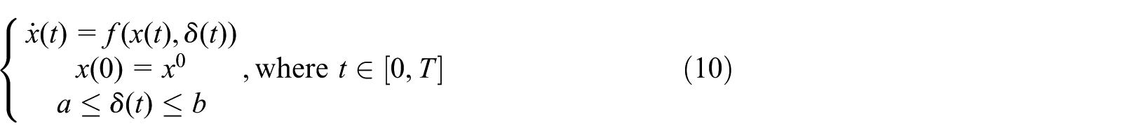
For the longitudinal process of UAV flight, the following reasonable assumptions can be made in order to simplify the analysis without affecting the simulation accuracy: 5
The UAV is rigid without considering its structure and elastic deformation. (Aeroelastic analysis of flexible large wingspan SP-UAVs will be considered as future work.)
The airframe is longitudinally symmetrical, that is, the aerodynamic shape and mass distribution are symmetrical, while the center of gravity for the airframe is unchanged, and the gyroscopic moment effect of the rotating parts inside the airframe is omitted.
The earth’s rotation and its curvature is disregarded, that is, treating the ground as a plane and assuming that the acceleration of gravity does not change with altitude.
In the benchmark movement, the symmetric plane is in the plumb position, where the roll angle is zero. Meanwhile, the motion plane overlaps with the vertical symmetric plane of the UAV, where the sideslip angle is zero.
This model does not consider the impact of the wind.
The kinematic equations of SP-UAV with six degrees-of-freedom (DOF) are established under the above assumptions. The motion of UAV in the space includes three DOF for the moving equations of barycenter and three DOF rotating equations around the barycenter. In addition, six equations are used to describe the change of the UAV’s position and attitude in space, and three geometric equations are used to describe the relationship between angles. 6 The ground coordinate system is established with the projection direction of the plane’s forward flight speed on the horizontal plane as the X-axis, as shown in Figure 2.
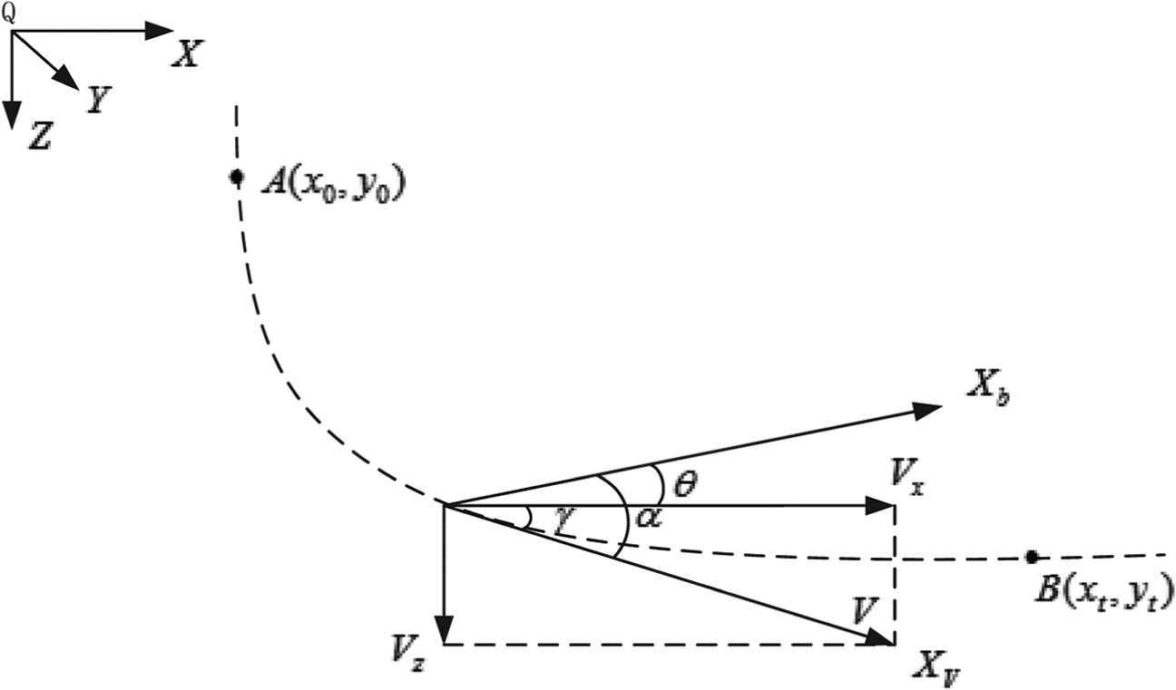
The longitudinal motion of SP-UAV.
Based on the above assumptions, it can be concluded that the longitudinal aerodynamic force and the derivative of aerodynamic moment to the lateral parameters in its base motion state equal to zero. The lateral aerodynamic force and the derivative of aerodynamic moment to the longitudinal parameters under the reference motion also equal to zero. Therefore, we may draw the conclusion that in the longitudinal motion disturbance, the longitudinal aerodynamic force and moment are only related to the longitudinal motion parameters. Based on this, the UAV moving equations can be decomposed into two independent groups: the longitudinal moving equations and the transverse moving equations. In this article, the longitudinal motion process is analyzed in detail, while the lateral-directional motion process is only studied in terms of controller design and response analysis.
The longitudinal motion equations of the SP-UAV can be simplified as
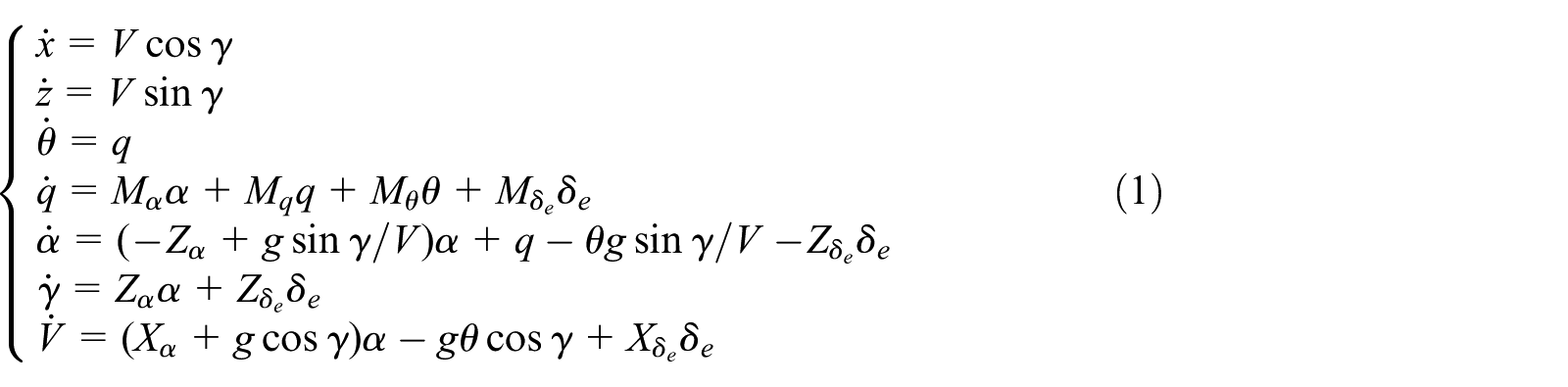
where the definitions for the parameters are listed in Table 1. The longitudinal motion of the UAV is unsteady motion, and its moving equation is variable coefficient differential equations. The solving process of a differential equation with variable coefficients usually adopts the coefficient freezing method. The principle is to transform the linear differential equation with variable coefficients into a linear differential equation with constant coefficients under certain conditions.
Parameter interpretation of longitudinal motion equations.

The launching process of the balloon-borne SP-UAV needs to cope with the following constraints:
The initial launching speed is 0, and at the end of the launching process, the UAV is cruising flight at a speed of V;
The initial pitch angle is denoted by
Limitations of the servo system. The control rudder effect is no greater than the maximum rudder offset value;
Requirements for the fuselage structure strength of the UAV in the launching process, that is, the maximum load during the launching process is less than or equal to the maximum design load allowed by the UAV fuselage structure.
Optimization problem formulation
To solve the optimal target pitch angle of the balloon-launched SP-UAV, the coordinate system transformation and the variable dimensionalization are required. We define
Through the transformation and dimensionalization processing, the mathematical model of the system can be formulated as
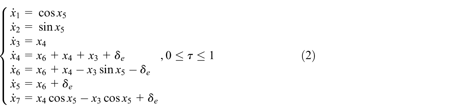
where

with the final constriction is

According to the initial conditions, the optimization problem for launching the SP-UAVs can be described as designing the optimal control law

The explanation of the objective function can be stated as follows. First, we analyze the first term of the objective function, that is, the normal load limit. After the UAV was separated from the balloon carrier, due to the limitation of the structural strength of the UAV’s fuselage structure, the normal load of the UAV during the launching-and-pulling process must be within the allowable range, with the normal load
Figure 3 shows the flight path of the UAV after the launching. We then analyze the flight phase according to equation (5). For the first item of the objective function, it is assumed that the speed of the UAV is

with

The physical meaning of R is the radius of the circle corresponding to the real-time track in the stage of launching and pulling process, with O being the center of the circle, as shown in Figure 3. At this time slot, the allowable radius of the UAV for the launching-and-pulling process is

States of the launching time slot.
The second term of the objective function is zero at the terminal pitch angle, which is
The third term of the objective function is to ensure a smooth transition of the UAV during the whole turning process, without stalling, destabilizing, and counter-direction forces. In this case, the angle of attack is required to be within the range of the UAV’s normal flight (
Throughout the process, each state can be treated as an instantaneous equilibrium point. Then, according to the equation

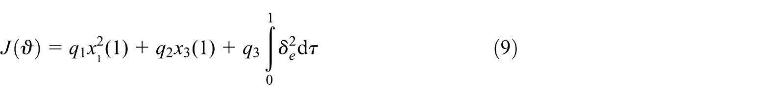
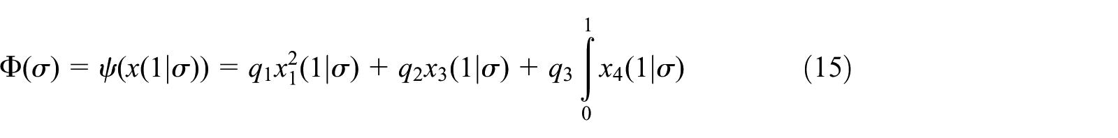
Then, the final objective optimization function can be expressed as minimizing 7
Optimal solution for the control problem
The above optimization problem is a typical optimal control problem, which can make the following transformation of the objective function into a standard form.
8
Let
where
Then, state equations of the UAV can be transformed into

The above optimal problem can be set as a new optimization problem, and then, we could utilize the CVP method to solve this problem.5,6 First, the time

The control variable parameterization method.
Then, it has

where

and

By substituting the discrete control variables in equation (9), we can obtain a new objective function
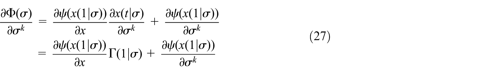
Through the above transformation, the original optimal objective function is transformed into a standard parameter-selecting optimization problem, which can be solved by the sequential quadratic programming (SQP) method. In order to facilitate the sequential quadratic optimization method to find the optimal value, the gradient information of the objective function with respect to the control quantity parameters needs to be calculated. The gradient of the objective function to the control quantity

which can be further expressed as

where

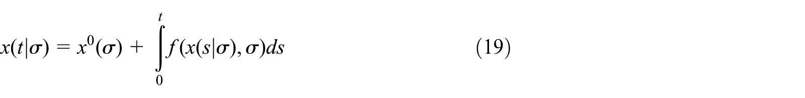
According to equation (1), the form of the solution to the state variable
Let

and

where l represents the number of the equally divided time intervals.
For

For the case of

For

Taking the derivative of equation (24) with respect to time, we can obtain

Then, we have

From equation (26), we could have the solution to
Then, the optimal pitch angle
Numerical results and performance analysis
According to the optimal solution designed in section “Optimal solution for the control problem,” the longitudinal direction is controlled by the pitch angle command, and the horizontal channel mainly carries out the zero control of the inclination angle in the launching and pulling-up stage, that is, the inclination angle is kept to be zero in the launching and pulling-up process. The course channel can be stabilized only by increasing damping, with its course can be any course angle after releasing and pulling-up. 11 The three-channel controller is designed for simulation analysis of the launching and lifting process of the SP-UAVs, 12 including the pitch angle response curve, the roll angle response curve, the yaw angle response curve, the flight angle of attack response curve, the load response curve, the height variation range, and the speed variation range.
Based on the above designed three-channel controller, we carry out our simulations in the following environment, see Tables 2 and 3. Figure 5 shows the curves of height–velocity, in which the left boundary is restricted by the stalling speed, while the right boundary is restricted by
Simulation environment and parameter settings.
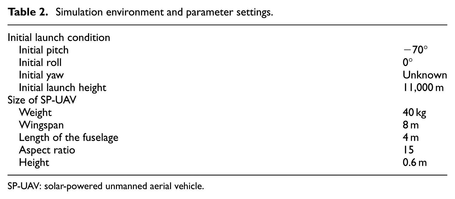
SP-UAV: solar-powered unmanned aerial vehicle.
The flight envelope of the SP-UAV.

SP-UAV: solar-powered unmanned aerial vehicle; TAS: True AirSpeed.

Flight envelope of the SP-UAV.
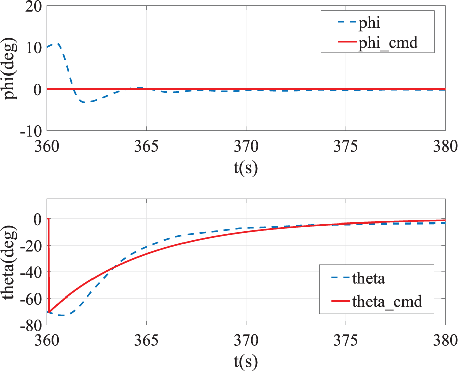
Roll and pitch commands and the tracking responses.

Yaw and attack of angle responses.

Height and true airspeed responses.
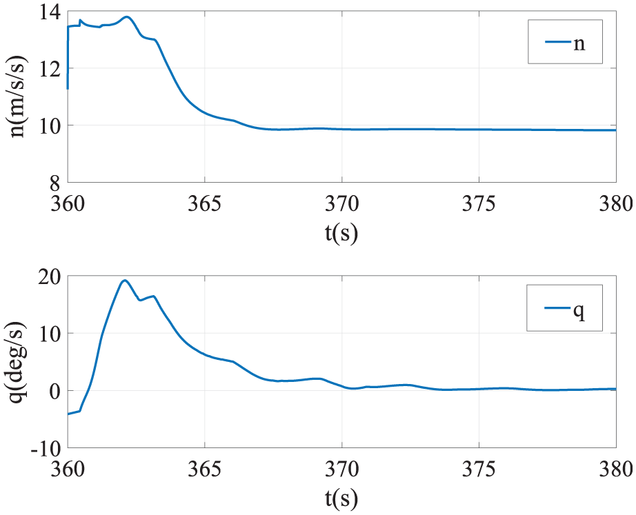
Normal load and pitch rate responses.
Figure 6 shows that in the process of launching and pulling-up, the roll angle (labeled as phi) is controlled to be −1°, while the pitch angle (labeled as theta) change instruction is stable, completing the instruction from −70° to the transition of −1° in 20 s. The pitch angle tracks fast, accurately, with little overshoot.
Figure 7 shows the changes of the course angle (labeled as psi) and the angle of attack (labeled as alpha). During the process of launching and pulling-up, the course angle is the initial course angle at the time of dropping, while it remains the original course angle during the pulling-up process. The angle of attack change curve shows that in the process of launching and pulling-up stage, the minimum angle of attack for the flight is −6°, and the maximum angle of attack flight is far less than its upper bound, within the range of allowable design.
In Figure 8, the changes of the height curve and the true airspeed (labeled as Vair) show that the flight height changes 100 m, and the maximum speed does not exceed 30 m/s during the launching and pulling-up process, meeting the requirements of the normal load for the SP-UAV.
In addition, the results of Figure 9 show that the normal load is less than 15 m/s2 and the maximum pitch rate appears at 2.1 s, while the normal load is 13.8 m/s2, which is safe for the plane structure.
The simulation results indicate that the controller designed by the CVP method is capable of pulling the solar UAV from the vertical zero initial velocity state to the horizontal cruise flight state, and the end speed of the launching and pulling-up stage is within the allowable range, with the flight angle of attack also within the allowable range of the design.
Conclusion
This article analyzes and designs the control scheme for the launching of a balloon-launched SP-UAV in near-space and conducts the mathematical modeling of the motion state for the UAV in the launching and pulling-up stage. An optimization method based on the parameterization of control variables is adopted to obtain the optimal pitch angle, which is further used as the longitudinal channel to control the desired pitch angle. In the meantime, the control design of transverse channel zero control and the course channel stability enhancement is adopted to meet the control requirements of balloon-launched SP-UAV. Numerical simulation tests show that the SP-UAV is capable of completing the transition from vertical to horizontal cruising flight in a relatively short time, with the flight angle of attack, the maximum speed, and the maximum normal load all within the allowable range during the pulling process, which verifies the feasibility of the launching mode by the balloon. For future research studies, one direction that worth studying is to further optimize and verify the launching and pulling-up control method and to carry out flight test verification.
Footnotes
Declaration of conflicting interests
The author(s) declared no potential conflicts of interest with respect to the research, authorship, and/or publication of this article.
Funding
The author(s) disclosed receipt of the following financial support for the research, authorship, and/or publication of this article: This paper is partially supported by the Scientific Experiment System in Near Space, Chinese Academy of Sciences, No. XDA17020401, and by the National Natural Science Foundation of China, No. 61901448 and No. 61871401, and Anhui Provincial Natural Science Foundation, 1708085MF139.