
Abstract
Polycrystalline diamond compact bits have been widely used in the Oil and Gas drilling industry, despite the fact that they may introduce undesired vibration into the drilling process, for example, stick-slip and bit bounce, which accelerate the failure rate and lead to higher drilling costs. First, we develop an innovative ridge-ladder-shaped polycrystalline diamond compact cutter, which has ridge-shaped cutting faces and multiple cutting edges with stepped distribution, in the hope of reducing vibration and improving drilling speed. Then, the scrape tests of ridge-ladder-shaped and general polycrystalline diamond compact cutters are carried out in a laboratory, indicating that the cutting, lateral, and longitudinal forces on ridge-ladder-shaped polycrystalline diamond compact cutters are smaller and with minor fluctuations. Due to different rock-breaking mechanisms, ridge-ladder-shaped polycrystalline diamond compact cutters have higher cutting efficiency compared to general polycrystalline diamond compact cutters, which is also verified experimentally. Finally, the drilling characteristics of a new polycrystalline diamond compact bit fitted with some ridge-ladder-shaped polycrystalline diamond compact cutters are compared to those of a general polycrystalline diamond compact bit by means of finite element simulation. The results show that introducing ridge-ladder-shaped polycrystalline diamond compact cutters can not only reduce the stick-slip vibration, bit bounce, and backward rotation of drill bits effectively, but also improve their rate of penetration.
Keywords
Introduction
Polycrystalline diamond compact (PDC) bit is the most common drilling tool, which interacts with rocks directly to create a passage from the ground to the bottom hole for oil and gas exploration. Statistically, PDC bits have been used for more than 90% total drilling length all over the world because of their high rock-breaking efficiency. 1 However, the service of a PDC bit is limited by the low impact resistance of its cutters. 2 When facing a difficult drilling formation, harmful vibrations appear, such as stick-slip and bit bounce, which have been identified as the main causes for PDC bit damage (see Figure 1) and low drilling speed, 3 increasing the drilling costs significantly. One of the effective measures to overcome these problems is the optimization of the bit design, especially the structure of a PDC cutter, which usually has a cylindrical shape. Some efforts and acquired results in this field will be briefly discussed next.
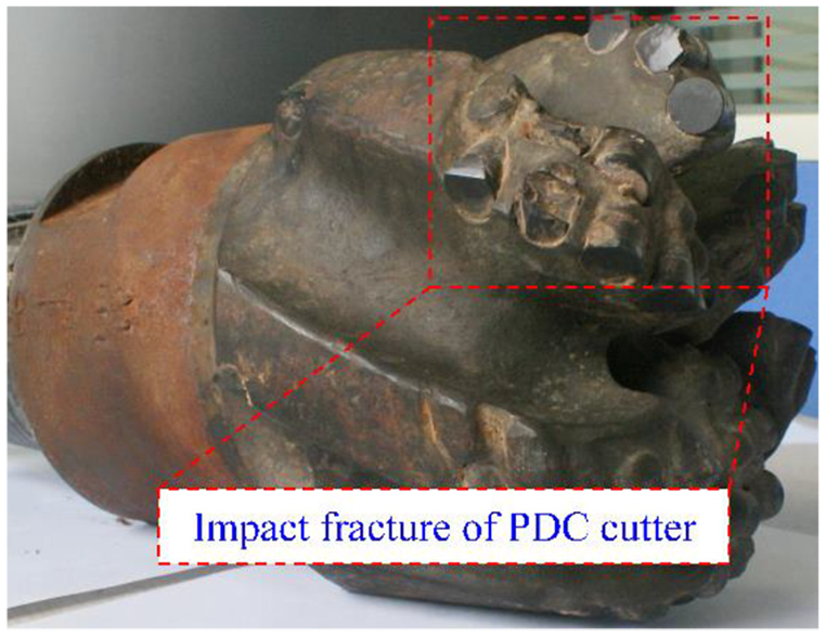
PDC bit damage caused by its undesired vibrations.
DiGiovanni et al. 4 proposed a non-planar face PDC cutter with shallow recessed features, which provided lower mechanical specific energy (MSE) and a higher drilling speed, compared to a general PDC bit under the same conditions. Schlumberger developed the ONYX 360 rolling PDC cutter which helped to reduce the wear and frictional heat issues of general PDC cutters, 5 prolonging the service life of a drill bit and improving its drilling speed. Rodriguez et al. 6 and Pak et al. 7 mentioned a hybrid-type bit fitted with both the general and conical PDC cutters. In the drilling process, the conical PDC cutter applies a concentrated point load to break rocks by plowing, and then the general PDC cutter creates a more efficient and durable shearing action. Crane et al. 8 introduced a PDC cutter with an elongated ridge which fractures and shears the rock at the same time, improving the rock-breaking efficiency of drill bits. Al-Ajmi et al. 9 developed a PDC cutter with a unique cutting structure to increase the stress concentration acting on the rock, offering more efficient cutting action than the general PDC cutter. As can be seen from this review, there is a lot of interest in the structural improvement of a drill bit, especially in the field of innovative design of PDC cutters, while most of the existing research aims to improve rock-breaking efficiency and optimize static mechanical characteristics of a full drill bit. However, research on adopting innovative PDC cutters to reduce the vibration is rarely reported in the scientific community.
This article introduces an innovative ridge-ladder-shaped (RLS) PDC cutter, which has ridge-shaped cutting faces and multiple cutting edges with stepped distribution, as shown in Figure 2. In principle, this new structure improves the stress concentration on rocks and lowers MSE, which would alleviate peeling large chunks of rocks effectively and instantaneous impact actions, reducing vibration and improving the rate of penetration (ROP). In order to verify this hypothesis, RLS PDC cutters and general PDC cutters are manufactured by using the 3D printing technique, followed by scrape tests carried out in a laboratory. Meanwhile, the rock-breaking mechanisms for both cutters are analyzed and compared with each other. In addition, the dynamic drilling behaviors of the general PDC bit and the new PDC bit fitted with some RLS PDC cutters are compared with each other by using finite element analysis.

The structure of RLS PDC cutter.
Scrape experiment of a single PDC cutter
In order to evaluate the cutting mechanical properties of RLS PDC cutters, a series of laboratory tests are carried out and compared with those of general PDC cutters. First, both types of PDC cutters, with a radius of 7.5 mm, are manufactured using a 3D printing technique and C45E4 steel, as shown in Figure 3. Then, the cutters are installed onto a specialized experimental rig designed to scrape the rock, while measuring the cutting, lateral, and longitudinal forces acting on the cutter. The directions of those forces are shown in Figure 4.

Experimental samples of two types of PDC cutters.
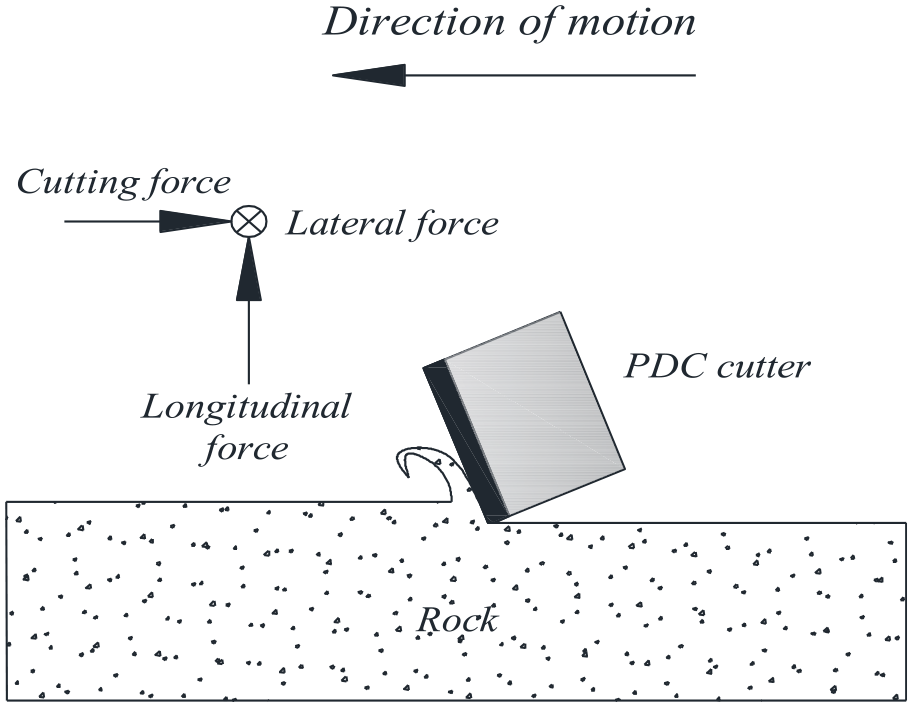
A schematic defining the directions of the typical forces on a PDC cutter.
Experimental rig and principles
The experimental rig shown in Figure 5 is designed to simulate the straight scraping of a PDC cutter, where the PDC cutter is soldered to the tooth holder connected to the load cell. The shaper machine drives the PDC cutter and scrapes the rock, measuring three orthogonal forces defined in Figure 4. The resulting three-phase current signals are collected by the data acquisition system (DAQ) and displayed in the Labview system. Ultimately, the forces acting on the PDC cutter are derived according to the calibrated relationship with the current signals.

A schematic (left) and photograph (right) of the experimental rig. Main components of the system include shaper, load cell, PDC cutter, rock sample, DAQ, and Labview system.
Experimental design
A key goal of the experiments is to compare the cutting mechanical properties of RLS PDC cutters with those of general PDC cutters. Therefore, both types are driven to scrape the rock with the same parameters, including the front rake of 15 degrees and the cutting depth of 3 mm. Under this condition, all the three cutting edges of RLS PDC cutters can participate in the scraping rock. Meanwhile, sandstone rock samples are utilized to avoid PDC cutter damage. Furthermore, in order to eliminate accidental errors, three PDC cutter samples in each category are selected and each PDC cutter sample scrapes the rock sample two times. Then, the six sets of the measured cutting, lateral, and longitudinal forces acting on each type of a PDC cutter are averaged to represent its cutting mechanical properties.
Experimental results
In Figure 6, an example family of time histories for the scrape experiments of RLS and general PDC cutters is presented. It can be seen that the cutting, lateral, and longitudinal forces acting on these two types of PDC cutters are always fluctuating. We selected the experimental results under the stable state (from step 200 to step 400) to calculate the average values and the root mean square (RMS) values of the three forces, which are listed in Table 1. It is important to state that step is a time scale related to the sampling frequency of DAQ.

A sample of the recorded experimental time histories of the forces acting on two types of PDC cutters, where step is a time measurement. (a) The cutting force; (b) the longitudinal force; and (c) the lateral force.
The average and RMS values of the forces acting on RLS and general PDC cutters.

RMS: root mean square; PDC: polycrystalline diamond compact; RLS: ridge-ladder shaped.
Through the comparison, it can be seen that the cutting, lateral, and longitudinal forces acting on RLS PDC cutters are less and have minor fluctuations compared to general PDC cutters, which indicates that the former has better cutting mechanical properties. Therefore, the unexpected vibration, for example, stick-slip and bit bounce, may be effectively mitigated by employing RLS PDC cutters, improving drilling speed and service life of a drill bit. Interestingly, the lateral forces acting on these two types of PDC cutters are at least 1 order of magnitude lower than the cutting and longitudinal forces, so that the lateral dynamical behaviors of any a full drill bit are ignored in subsequent research.
Rock-breaking mechanism analysis
According to the experimental conditions given in Section 2, both general and RLS PDC cutters are imposed to move with constant horizontal velocity

Sketch of a sharp general PDC cutter scraping a rock on (a) longitudinal cross-section 1 and (b) lateral cross-section.
It is assumed that

where
According to the geometrical relationships shown in Figure 7, the work area of a general PDC cutter on its cutting face can be given by the shaded area of Figure 8, in which

For a RLS PDC cutter, its ridge-shaped cutting faces and cutting edges with stepped distribution do not change the cylindrical shape of the cutter. Therefore, under the same radius, front rake, and depth of cut, RLS PDC cutters will generate a notch of the same cross-section area as the general PDC cutter, which means that

where

Cutting face of the general PDC cutter, where the shaded area is its work area.
The experimental results given in Section 2 indicate that RLS PDC cutters have better cutting mechanical properties than general PDC cutters, which is due to the former’s special structure. As shown in Figure 9(a), the cutting edges with stepped distribution can decompose a total depth of cut

Sketch of a sharp RLS PDC cutter scraping rock on (a) longitudinal cross-section and (b) lateral cross-section.
In order to verify the previous statement, the values of
Effect of RLS PDC cutters on drilling performance
In order to obtain the performance of RLS PDC cutters under drilling conditions, the drilling behaviors of a new PDC bit fitted with some RLS PDC cutters are simulated using the finite element analysis method and are compared with those of a general PDC bit. The geometric models of the new and general PDC bits are illustrated in Figure 10(a) and (b), respectively, and their only difference is demonstrated only in their main PDC cutters, which are marked by the blue and red dotted ovals, respectively.

Geometric models of two kinds of PDC bits used in simulation. (a) New PDC bit and (b) general PDC bit.
Finite element models
In this section, the finite element models of these two kinds of PDC bits drilling rocks are established by using ABAQUS software, as shown in Figure 11. Any finite element model includes three parts: reduced scale drill-string, drill bit, and rock. The reduced scale drill-string is composed of rotary table, flexible shaft, and bottom hole assembly (BHA), which are discretized using eight-node hexahedron reduced elements (C3D8R). The same element type is used for discretization of the rock. In addition, the four-node 3-D bilinear rigid quadrilateral unit (R3D4) is employed to mesh two types of PDC bits, which are modeled as discrete rigid bodies.

Finite element models of the new and general PDC bits drilling rocks.
Nonlinearities of a full drill bit breaking rocks
A full drill bit breaking a rock is a complicated process and includes three main nonlinearity types, 12 for example, (i) the geometric nonlinearity caused by the large rotation and large drilling footage of a drill bit, (ii) the material nonlinearity caused by the large plastic strain to the occurrence of failure and even elimination of rock units, and (iii) the contact nonlinearity excited by the dynamic contact between the drill bit and rock, which is due to the combined action of the first two. In order to better understand the rock-breaking behaviors of a full drill bit, all the factors leading to nonlinearity should be mathematically expressed.
Dynamic model of the drill bit–rock interaction
Based on the finite element method, we set the occupying space domain of a contact system at any time

where

where
Rock constitutive relation
The true stress–strain behavior of rock materials has obvious nonlinearities, which make numerical solution and simulation difficult. In order to balance calculation accuracy and cost, the Drucker–Prager strength criterion, which treats deviatoric stress as the primary cause of rock damage and can reflect the influence of volume stress on rock strength, is usually used to establish the constitutive model of the rock approximately,14,15 especially in research for rock breaking of a full drill bit reported in this article. According to this criterion, the intermediate principal stress has an influence on rock damage, which is indicated by the normal stress

where

in which
For compression hardening,

For tensile hardening,

For shear hardening,
Rock damage criterion
It is known from damage mechanics that rock destruction is not a state but a process. Figure 12 shows a characteristic stress–strain curve of a rock, which indicates that there are three main stages from starting bearing load (point a) to complete damage (point d) of a rock, including a linear elastic stage (a–b), a plastic yield stage (b–c), and a damage evolution stage (c–d). In this figure,

The stress–strain curve with rock damage evolution.
In Figure 12, the damage factor

where
After comprehensive consideration, the plastic strain

Boundary conditions and loading
The configuration of the FE model indicating boundary conditions and loads is shown in Figure 13, which is established on the basis of previous efforts.
19
It can be seen that the lower surface of the rock is fully fixed. Meanwhile, the lateral motions of the rotary table and PDC bit are restricted and their rotations around both

Configuration diagram of boundary conditions and loads, in which
Results and discussion
The angular velocity curves of the general and new PDC bits are shown in Figure 14. It can be seen that both kinds of PDC bits exhibit stick-slip vibration of different degrees, with repeated alternation of stick and slip phases. In the stick phase, the angular velocities of both PDC bits are equal to 0. Once they get into the slip phases, their angular velocities can be accelerated to several times higher than rotary table speed

Angular velocity time history curves of the general and new PDC bits, where the black dotted line represents the angular velocity of 0 rad/s.

Interestingly, the backward rotation of the general PDC bit can be observed during its drilling process, which manifests as the rotational velocity less than 0, but this is not observed for the new PDC bit, as illustrated in Figure 14. For the general PDC bit, its backward rotation tends to cause a reversed reaction torque from the rock, which is represented as a torque greater than 0 (in the driving direction), as shown in Figure 15. For a single PDC cutter, a reversed cutting force

Reaction torque acting on the general and new PDC bits from a rock, where the black dotted line represents the torque of 0 kN.m.

Force diagram of a PDC cutter during backward rotation.
In addition, particular attention is given to the axial motions of both kinds of PDC bits. As can be seen from Figure 17(a), both the general and new PDC bits experience bit bounce of different degrees in the drilling process, which is characterized by the negative ROP for a short time interval. However, the bounce of the general PDC bit is more severe than that of the new PDC bit. In addition, the average ROPs of the general PDC bit and the new PDC bit are 6.428 and 6.487 mm/s, respectively, and their RMS values are 13.614 and 8.145 mm/s, respectively. Therefore, it can be said that the use of RLS PDC cutters can not only reduce the axial vibration of a full drill bit, but also improve its axial drilling speed, which is clearly demonstrated by the fact that the new PDC bit has a deeper drilling depth, as shown in Figure 17(b).

Time history responses corresponding to the axial motions of the general and new PDC bits, where the black dotted line represents the drilling speed of 0 mm/s. (a) ROP and (b) footage.
Based on the above results of finite element analysis, it can be concluded that introducing RLS PDC cutters will effectively mitigate the undesired dynamic behaviors, such as stick-slip and bit bounce, which should help to prolong the service life of a drill bit and increase the efficiency of rock breaking. As a positive result, the drilling speed will have a noticeable improvement. Once again, it is important to emphasize that the primary purpose of this article was to propose a new PDC cutter structure to improve drilling performance (for example, vibration reduction and drilling speed improvement) and preliminarily demonstrating whether it reaches the expected goals or not. Therefore, this study is not involved in the processing technology of the new PDC cutter and its comprehensive influence on economic benefit, which will be further discussed in the future research.
Conclusion
We propose a RLS PDC cutter which has ridge-shaped cutting faces and multiple cutting edges with stepped distribution. This innovative cutting structure improves stress concentration acting on a rock and lowers MSE. Therefore, we hope to improve cutting efficiency and reduce instantaneous impact actions by adopting this new PDC cutter, reducing vibration, and improving the ROP.
RLS and general PDC cutters are manufactured by using the 3D printing technique and their scrape tests are carried out in a laboratory. The test results indicate that the cutting, lateral, and longitudinal forces acting on a RLS PDC cutter are smaller with less fluctuations compared to those acting on a general PDC cutter. Therefore, it can be concluded that a RLS PDC cutter has better cutting mechanical properties. In addition, it can also be concluded from test results that a RLS PDC cutter has higher cutting efficiency because of its particular rock breaking mechanism.
The drilling behavior characteristics of a new PDC bit fitted with some RLS PDC cutters are compared to those of a general PDC bit by means of finite element simulation. Simulation results show that introducing RLS cutters can reduce the stick-slip vibration, bit bounce, and backward rotation of a drill bit effectively, improving subsequently the ROP.
Footnotes
Declaration of conflicting interests
The author(s) declared no potential conflicts of interest with respect to the research, authorship, and/or publication of this article.
Funding
The author(s) disclosed receipt of the following financial support for the research, authorship, and/or publication of this article: This study was financially supported by the Sichuan Science and Technology Program (No. 2019YJ0536) and the National Natural Science Foundation of China (No. 51904263).