
Abstract
Carbon fiber–reinforced carbon matrix composites have been widely used for the manufacturing of thermostructural parts for several industries such as the aerospace and automotive. Drilling is an extremely common method used in the machining of carbon fiber–reinforced carbon matrix composites before assembly. However, their non-homogeneous, anisotropic, and brittle nature make difficult to guarantee the hole quality in drilling. Some severe drilling defects, such as burrs, delamination, and tear, usually occur. In this regard, it is necessary to accurately predict the thrust force in drilling of carbon fiber–reinforced carbon matrix composites. Therefore, in this article, based on the cutting theory of fiber-reinforced polymer composites, an alternative thrust force prediction model for drilling of bidirectional carbon fiber–reinforced carbon matrix composites is proposed. The cutting force of the cutting lips is established by dividing the cutting deformation zone into three regions according to the machined material structure based on the Zhang’s model in cutting of fiber-reinforced polymer. The periodic variation of fiber orientation is considered in detail. The experimental results show that the relative deviations of the predicted and experimental values of the thrust force are less than 14.36%.
Introduction
Carbon fiber–reinforced carbon matrix (C/C) composites are the only hyper high-temperature materials that can maintain mechanical properties at room temperature over 2000°C. 1 They present some excellent properties, such as low thermal expansion coefficient, high heat resistance, high specific stiffness, and high resistance to corrosion. Due to these special features, they have been widely applied in a great number of fields for several decades, especially in the aeronautic, aerospace, sports, and automotive industries. 2 The preform of bidirectional C/C composites is commonly formed with bidirectional fibers. The chemical vapor infiltration technique is applied to generate the carbon matrix in the preform.
In conventional manufacturing, drilling with a twist drill bit is one of the most commonly used methods in the machining of holes required for the composite assembly, accounting for about 40% of all removed materials. However, their non-homogeneous and brittle nature make difficult to guarantee the hole quality in drilling of C/C composites. The most commonly defects are burrs, delamination, and tear in drilling of C/C composites. In order to overcome these problems, it is very necessary to develop suitable methods to gain appropriate cutting parameters in drilling of C/C composites.
It is well known that the cutting force is the most important factor in reducing drilling defects of composites. There are extensive literatures about the influence of cutting force (thrust force) in drilling of composites. In 1990, Ho-Cheng and Dharan 3 first studied the concept of critical thrust force in drilling of composite laminates. Chen 4 found that it was possible that drilling method suppressing delamination could be gained by selecting suitable tool geometries and drilling parameters in drilling of carbon fiber–reinforced polymer (FRP) composites. Tsao 5 reported that the delamination induced by the thrust force in drilling at the exit of hole could be avoided if the thrust force could be controlled below a critical thrust force. Rubio et al. 6 investigated that high speed machining could reduce defects during drilling of glass FRPs by experiments. Kerrigan and Scaife 7 found that dry drilling could reduce torque and make more holes than drilling with any cutting fluid in the cutting tests of carbon FRPs. Shan et al. 8 reported that rotary ultrasonic drilling could improve the hole quality compared with high speed drilling and conventional twist drilling methods in the drilling tests of C/C composites within their selected cutting parameter range.
There have been a large amount of efforts developing prediction models of cutting force and investigating the cutting mechanism of drilling. One of the models for the prediction of cutting force in drilling of composites is the empirical equation model using test data. Langella et al. 9 proposed a mathematical prediction model for thrust force and torque in drilling of composites. The coefficients in their model must be recalculated by a simple linear relation equation once the tool geometries or materials were changed. To analyze the influences of cutting parameters on delamination factor, Karnik et al. 10 established an artificial neural network prediction model with point angle of twist drill bit, feed rate, and spindle speed as the input parameters. They reported that high speed machining was helpful to control the delamination during drilling. By assuming that the distributions of cutting force along the chisel edge and the cutting lips of a drill bit is continuous, Wang and Zhang 11 presented a cutting force prediction model incorporating tool geometries and cutting process parameters. In their model, the cutting lips and the chisel edge were taken as oblique cutting and orthogonal cutting, separately. Zhang et al. 12 presented an analytical mechanical model for drilling of carbon FRPs based on composites mechanics, linear elastic fracture equations, and classical bending thin plate theory.
Cutting simulation has become a very effective method to optimize tool geometries and cutting parameters for controlling hole quality and analyzing the evolution of tool wear. 13 Taking the workpiece as an equivalent homogeneous anisotropic material, He et al. 14 constructed a three-dimensional (3D) macro finite element (FE) model for drilling of carbon FRPs using the ABAQUS software tool. Usui et al. 15 proposed a FE method using a large deformation, nonlinear Lagrange equation with an explicit integration for orthogonal cutting and drilling of unidirectional carbon FRPs. Based on the Shokrieh–Lessard’s model 16 and the Hashin’s failure criteria, Shan et al. 17 presented a damage initiation model and a 3D progressive failure model in the FE simulation for drilling of 2.5 dimensional (2.5D) C/C composites.
In summary, although the empirical modeling method has a certain practical value, it requires a experiments and data accumulation. Once the cutting parameters, tools, or process equipment are changed, the prediction accuracy of the empirical formula will definitely decrease, and the test and data accumulation have to be repeated. Compared with the costly empirical modeling method, as an alternative method, the FE method can offer a visible of cutting process and is a reliable method for defects prediction. 18 However, its calculation process is complicated and time-consuming. And the simulations for composites drilling are mostly concentrated on composite laminates (such as carbon FRPs), but few studies on C/C composites.
In this article, an improved mechanistic prediction model of thrust force in drilling of bidirectional C/C composites using a carbide twist drill bit is proposed. The effects of fiber orientation and cutting parameters are considered in this model. Experimental cutting tests are carried out and results are compared with the predicted results to verify the validity of the proposed model.
Modeling of thrust force
Generally, in the modeling of the thrust force for a twist drill bit, the chisel edge and the cutting lips of the twist drill bit are always analyzed as two distinct separate zones, then summing them up to obtain the total thrust force.
The influence of cutting temperature is not included in the model. Bidirectional C/C composites are anisotropic and can be regarded as a brittle material without plastic formation during the drilling process according to the literature reviews. The variation of the friction between the tool, chip, and workpiece during the drilling process is neglected. The filled chopped carbon fiber felts between fiber plies of bidirectional C/C composites are considered to have the same properties as carbon matrix.
Cutting force on chisel edge
Many years ago, Kachanov 19 and Langella et al. 9 reported that a small region all-round the center point of a drill bit does not cut, but only extrude the material, which is then cut off by the main cutting lips. Hence, the chisel edge is commonly regarded as orthogonal cutting with negative rake angle by many researchers.4,11,20–22 However, to be precise, it is not enough to describe the cutting force trend of chisel edge satisfactorily.
During drilling process, the chisel edge is pushed into the workpiece primarily like a wedge, and then the cutting lips begin to cut materials. Figure 1 shows the relevant geometries and cutting force components in the section plane of the chisel edge. According to the theory of contact mechanics, 23 the average stress κ generated when a rigid wedge is push into a workpiece could be expressed as


Geometrical relationship of chisel edge.
where dP is the elemental load acting on the rigid wedge, dP=dFc, and dFc is the elemental force of the chisel edge. τs is the maximum yield stress value of the workpiece material in pure shear. ψs is the sector angle of the slip line field of the extruded material, 2a is the contact length of the chisel edge, and dr is the elemental axial length perpendicular to the section plane, as shown in Figure 1. On the one hand, the wedge angle γw of the chisel edge could be calculated by Johnson 23 as

On the other hand, the wedge angle γw of the chisel edge could be calculated by

where p is the half of the twist drill bit point angle, and ψ is the chisel edge angle as shown in Figure 1.
In the beginning, the cutting lips of the twist drill bit would not start cutting the workpiece until the chisel edge has penetrated into the workpiece to a cutting depth g equal to fr/2 (two cutting lips). fr is the feed rate per revolution of the twist drill bit. Then the contact length 2a can be expressed by

As shown in Figure 1, the resultant cutting force dFc acting on the chisel edge can be decomposed to the cutting force dFcv along the thrust direction and the cutting force dFch along the velocity (νc), then

where γd is the total cutting speed angle and can be calculated by Wang and Zhang 24
Then

Then according to equations (1) and (6), the total cutting force acting on the chisel edge is

Cutting force on cutting lip
Mechanics model of cutting lip
Bidirectional C/C composites are made by alternating 0° and 90° unidirectional carbon fiber plies as shown in Figure 2(a). According to Zhang et al., 25 the mechanics model at a certain point p can be treated as three cutting deformation regions, namely, chipping, pressing, and bouncing regions, separately.

Mechanics model of cutting lips: (a) structure of bidirectional C/C composites and (b) illustration of the chip formation at pint P. 25
Region 1
The first cutting deformation region is a chip formation zone. Due to the structure characteristics of bidirectional C/C composites, the shear strength of carbon fiber is much larger than carbon matrix. Because of the poor bonding performance of the carbon fiber and the carbon matrix of C/C composites, the interlaminar shear strength becomes very low, resulting a near step-like shear plane formed in drilling 26 as shown in Figure 2(b).
As shown in Figure 3, the cutting force F of the drill bit acting on the chip can be resolved into two components. One is the pressure force Fn against the chip, and the other is the friction force Ff. The reaction force F′ of the workpiece acting on the chip can be resolved into the pressure force Fn and the shear force Fs. The shear force Fs can be resolved into Fs1 and Fs2 components. The cutting force Fs1 is perpendicular to the fiber orientation. The cutting force Fs2 is parallel to the fiber orientation. F and F′ are equal with each other in magnitude and in opposite directions.
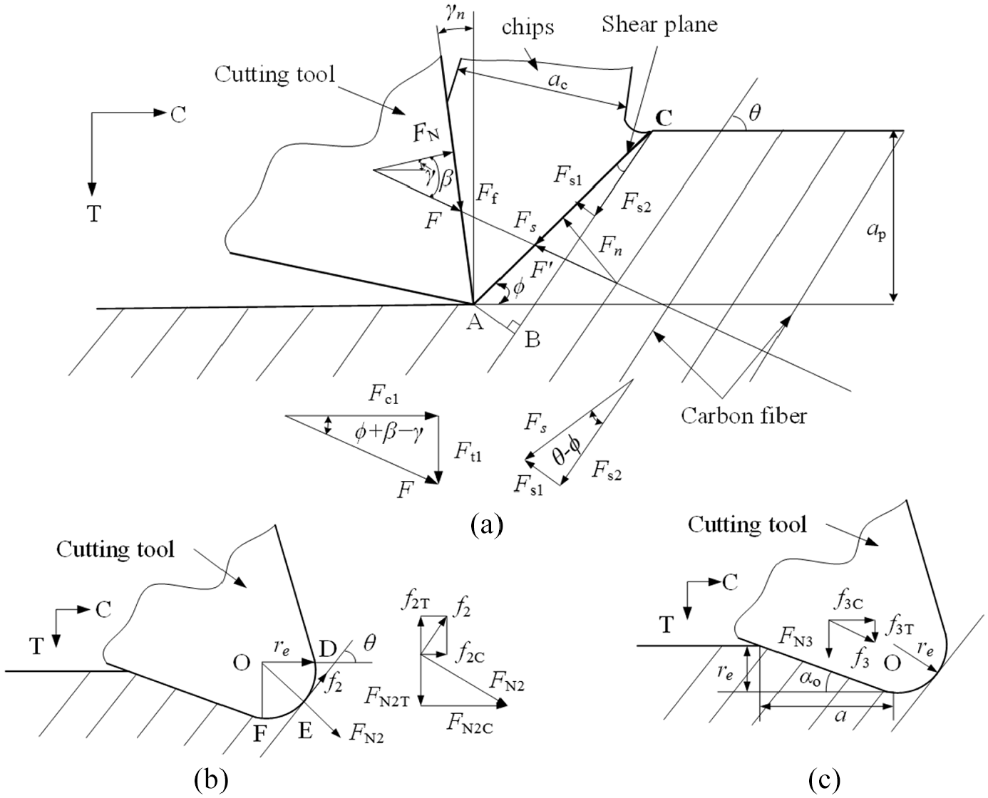
Illustration of the three deformation regions at point P: (a) cutting forces in region 1, (b) cutting forces in region 2, and (c) cutting forces in region 3.
As shown in Figure 3(a), the elemental length dl is a small segment on the main cutting lip. The elemental shear forces dFs1 and dFs2 in the section plane perpendicular to the main cutting lip can be expressed as 25

where τ1 and τ2 are the shear strength of carbon fiber and carbon matrix, respectively, θ is the fiber orientation angle, ϕ is the shear angle, and ap is the cutting depth.
Then, the elemental shear force dFs can be given as

According to the geometrical relationship in Figure 3(a)

where β is the friction angle on the rake face of the tool, and γn is the rake angle of the tool.
Then the tangential force FC1 and the feed force FT1 can be given as 25

The shear angle ϕ can be expressed by

where rc=ap/ac, ac is the chip thickness. In light of the brittle nature of C/C composites, rc= 1 in this article.
Then

Region 2
A simplified diagram of region 2 is shown in Figure 3(b). According to contact mechanics, 23 the tool nose can be treated as a cylinder rolling on a plane, and the acting load dFN2 can be expressed as

where re is the radius of the tool nose, and E2 is the effective elastic modulus of the workpiece material in the second deformation zone and can be given by

where E and ν are the elastic modulus and Poisson’s ratio of the bidirectional C/C composite, respectively.
Due to the elastic deformation of the second cutting deformation zone, the effective pressure force

As shown in Figure 3(b), the friction force f2 can be obtained by

where μ is the friction coefficient of the bidirectional C/C composite.
Thus, the tangential and feed elemental cutting forces, dFC2 and dFT2, in region 2 can be expressed by equation (18)
25
in terms of the effective pressure force

Region 3
The third cutting deformation region is a rebound zone. It is caused by the interaction of the clearance face of the tool and the machined surface of the workpiece. In order to simplify the calculation, it is assumed that the bouncing back height is equal to re.
According to contact mechanics, 23 the pressure force FN3 can be calculated by

where a is the contact length between the clearance face of the tool and the machined surface, α0 is the clearance angle of the tool. E3 is the effective elastic modulus of the workpiece material in the third deformation zone. E3 is set to KE times of E, and KE is set to 0.35 in this article.
The frictional force f3 between the workpiece and the tool shown in Figure 3(c) can be decomposed into two components f3C and f3T in the horizontal direction and the vertical direction, respectively. Hence, the elemental cutting forces dFC3 and dFT3 in horizontal and vertical directions in the third deformation zone can be expressed as

The total cutting forces, dFC and dFT, can be expressed as 25

Fiber orientation angle
As shown in Figure 4, it is assumed that the 0° fiber ply is parallel to MN, and the 90° fiber ply is perpendicular to MN. Point H is an arbitrary point on the cutting lip in the cross section of a twist drill bit. The fiber orientation angle θ is defined to be the angle between the 0° fiber ply and the cutting speed direction of point H. At the beginning, it is assumed that the fiber orientation angle θ of point H is θ0 at time t0. At time t, the point H moves to H′, and the fiber orientation angle of point H comes to be θ(t). Hence, for the 0° fiber ply, the rotation angle θ(t) can be expressed by

For the 90° fiber ply, the fiber orientation angle θ′(t) can be gained by


Illustration of fiber orientation angle.
Total thrust force
As shown in Figure 5, there is an inclination angle i between the normal direction of the cutting lip and the cutting speed, which can be expressed as

where α is the angle between the cutting speed v and its x direction component, which is related to the radius r of point Q, and can be obtained by

where w is the half of the drill bit web thickness.
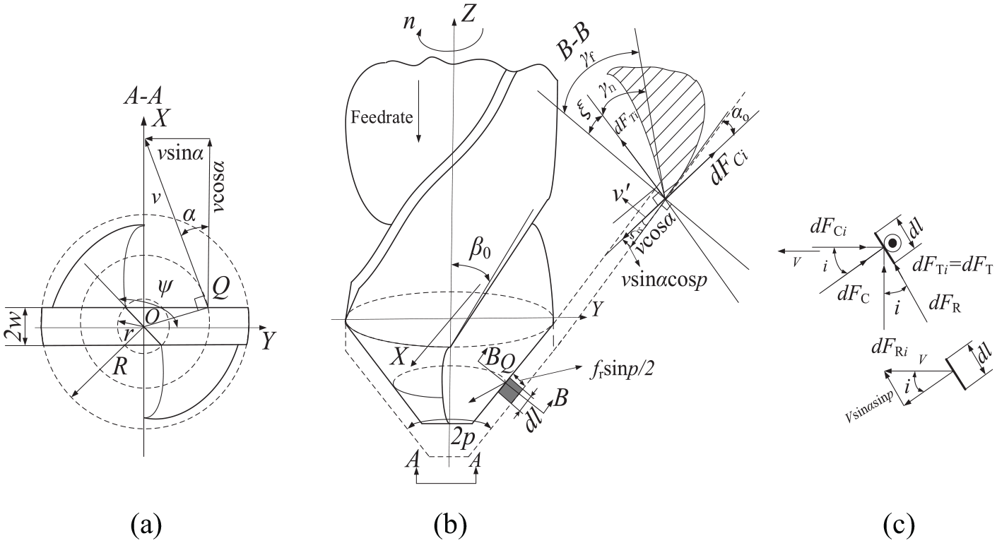
Geometry model of a twist drill bit. (a) Bottom view; (b) front view; and (c) diagram of force decompositon.
In the normal plane perpendicular to the cutting lip at point Q in Figure 5, the projection vector of cutting speed v in the normal plane can be resolved into two components: the component perpendicular to the cutting lip and the component parallel to vx. The angle ξ between the two velocity components can be calculated by

According to the geometrical relationship in Figure 5, the normal rake angle γn can be expressed as

where γf is the reference rake angle, which can be calculated according to the calculation formula proposed by Armarego 27

where δ is the local helix angle of point Q.
Assuming that the helix angle of the drill bit is δ0, the local helix angle δ of point Q can be calculated by

The length l of cutting lip can be obtained as

where d is the chisel edge length, then

Then dFR can be expressed as

where η is the chip flow angle.
According to Stabler, 28 the chip flow angle η can be approximately equal to the inclination angle i. According to the geometrical relationship in Figure 5 and Altintas 29

Then

Then the total cutting force Flip of the two cutting lips can be expressed by

The total thrust force, FZ, are the summation of the cutting forces of the cutting lips and the chisel edge, that is

According to Altintas, 29 shear angle, average friction angle, average friction factor, shear strength of C/C composites, and other values can be obtained by orthogonal cutting tests.
Similarly, the total torque is the summation of the torque of the cutting lips and the chisel edge. The calculation method of torque can be found in Wang and Zhang, 11 which is not discussed in this article.
Experimental procedure
To validate the developed model, a group of cutting experiments is conducted. The experimental equipment is a JOHNFORD-VMC850 four-axis control numerical control (CNC) machine tool with a FANUC-OI-MB NC unit. Its maximum spindle speed is 8000 r/min and its maximum power is 22 kW. The workpiece, which is cut from a part, is a bidirectional C/C composite thin plate composed of about seven plies and with thickness equal to 6 mm, as shown in Figure 6. First, the preform of the part is prepared by laminating unidirectional carbon fiber plies one over another in a 90° cross and filling chopped carbon fiber felts between adjacent plies. Then, the chemical vapor infiltration technique is used to generate the carbon matrix in the preform.

Bidirectional C/C composite thin plate.
Four conventional two-lip cemented carbide twist drill bits of 6 mm in diameter with a 118.8° angle are used, which is shown in Figure 7. The cutting force signal acquisition system consists of a Kistler 9255B type three-component dynamic dynamometer, a Kistler 5080A multi-channel charge amplifier, a Dewesoft DEWE3010 data collector, and DEWESoftX software. The experimental setup is shown in Figure 8. Because the cutting forces in three directions of X, Y, and Z can be acquired by the three-component dynamic dynamometer, the cutting force measured in the Z-direction is exactly the thrust force. However, because of the limitation of the equipment conditions, the torque cannot be directly measured in these experiments by the three-component dynamic dynamometer. Hence, the torque is not compared with the prediction value in this article.

Conventional two-lip carbide twist drill bits.
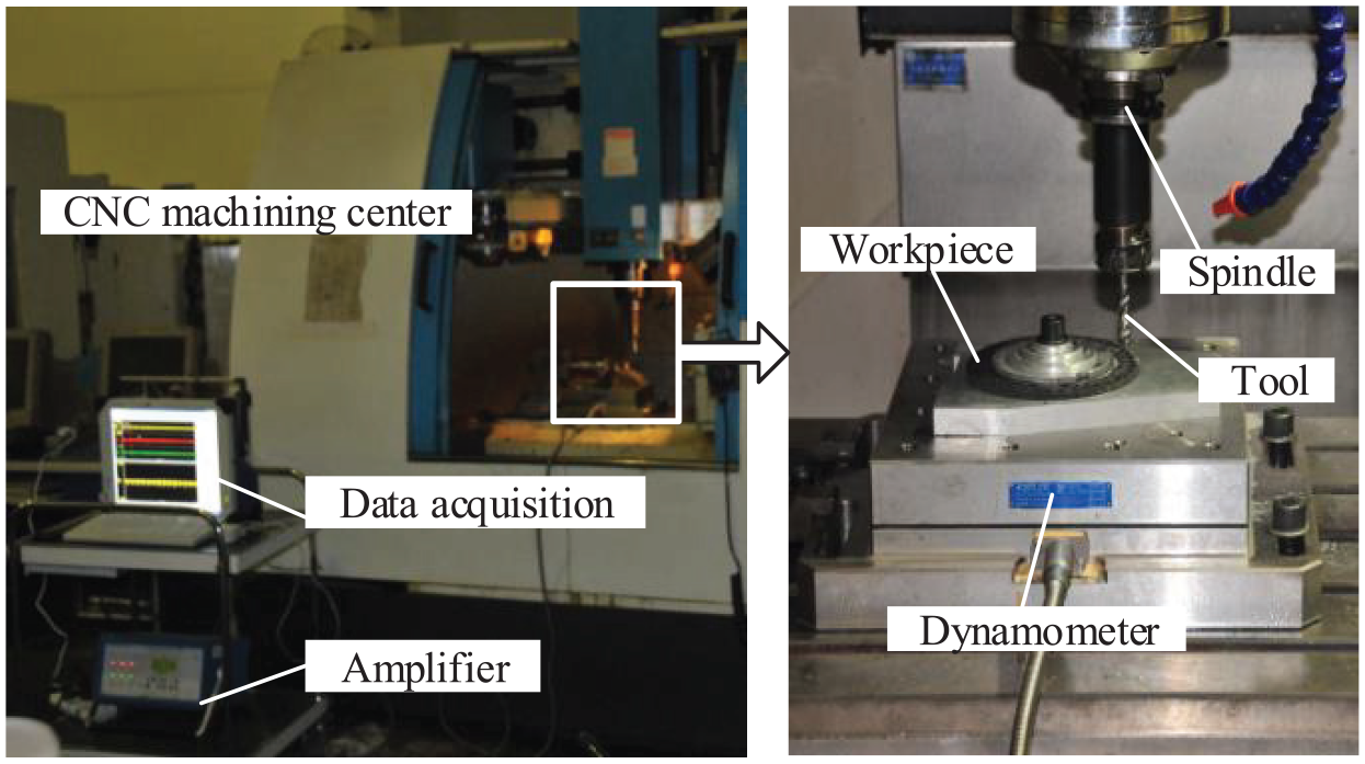
Experimental setup for drilling of the bidirectional C/C composite workpiece.
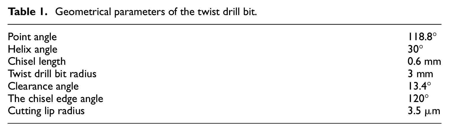
The geometrical parameters of the twist drill bit and the material properties of the workpiece are shown in Tables 1 and 2, respectively. The cutting parameters used in the experiments are shown in Table 3. The experiments are conducted using a single factor method without coolant. The average thrust force obtained from three repeated experiments is adopted as the experimental result. Hence, each twist drill bit is used 12 times at the same spindle speed for four different feed rates.
Geometrical parameters of the twist drill bit.
Material properties of the workpiece.

Cutting parameters used in the experiments.

Results and analysis
Figure 9 shows the measured thrust force signals under the cutting parameters of n= 1000 r/min and vf= 150 mm/min. The drill bit begins to cut at time B. In the beginning, as the twist drill bit advances, the thrust force increases quickly. From time B to C, the thrust force is mainly caused by the chisel edge of the drill bit. From time C to D, the chisel edge has immersed into the workpiece and the cutting lips of the drill bit begin to cut. From time D to E, the thrust force increases slightly, mainly because the friction force between the tool and the workpiece increases a bit with the increasing of cutting depth. From time E to F, the thrust force quickly drops to near zero with the twist drill bit coming out of the workpiece.
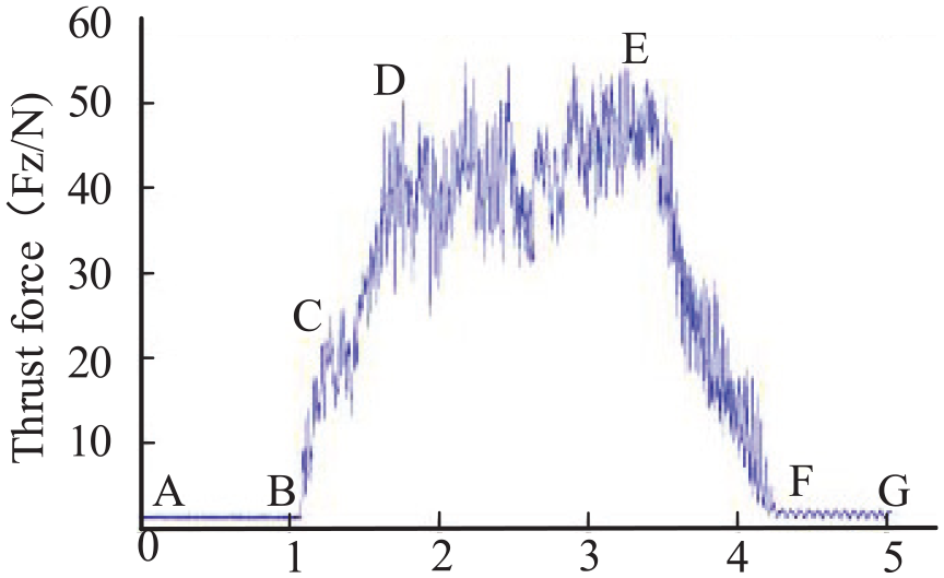
Measured thrust force signals (n= 1000 r/min, vf= 150 mm/min).
The experimental and predicted values of the thrust force are compared in Table 4. It can be seen from it that the maximum relative deviation of the thrust force is about 14.36%, and the minimum value is about 1.67%.
Experimental and predicted values of the thrust force.

Figure 10 shows the variation trends of the experimental values of the thrust force versus spindle speed. It can be seen that the experimental values of the thrust force fall gradually with the rising of spindle speed from 1000 to 4000 r/min. These trends are similar for different feed rates from 60 to 150 mm/min. Figure 11 shows the variation trends of the experimental values of the thrust force versus feed rate. It can be seen that the experimental values of the thrust force rise approximately linearly with the rising of feed rate. These trends are also similar for different spindle speeds from 1000 to 4000 r/min. Moreover, the rising trends of the thrust force gradually slow down as the spindle speed increases. As the feed rate increases from 60 to 150 mm/min, the thrust force rises approximately 85% when n= 1000 r/min; however, the thrust force only rises about 40% when n= 3000 r/min.

Experimental values of the thrust force versus spindle speed.

Experimental values of the thrust force versus feed rate.
Figure 12 shows the comparison of the experimental and predicted values of the thrust force for different spindle speeds as the feed rate increases from 60 to 150 mm/min. The predicted values show a good agreement with the experimental results especially when n= 2000 and 3000 r/min.

Comparison of the predicted and experimental values of the thrust force for different spindle speeds: (a) n= 1000 r/min, (b) n= 2000 r/min, (c) n= 3000 r/min, and (d) n= 4000 r/min.
Figure 13 shows the comparison of the experimental and predicted values of the thrust force for different feed rates as the spindle speed rises from 1000 to 3000 r/min. The predicted values show a good agreement with the experimental results especially when vf= 60 and 90 mm/min. Therefore, the thrust force can be reduced by increasing spindle speed and decreasing feed rate in the selected cutting parameter range. In order to reduce the defects in drilling of C/C composites, higher spindle speeds and lower feed rates should be selected in low speed machining.

Comparison of the predicted and experimental values of the thrust force for different feed rate: (a) vf= 60 mm/min, (b) vf = 90 mm/min, (c) vf = 120 mm/min, and (d) vf=150 mm/min.
Conclusion
The prediction of thrust force is very important for controlling the defects of composites in drilling process. An analytical mechanical model for predicting the thrust force is presented in drilling of bidirectional C/C composites. The cutting force of the cutting lips is established by dividing the cutting deformation zones into three regions based on the Zhang’s model in cutting of FRPs. The cutting force on chisel edge is established according to the theory of contact mechanics and orthogonal cutting. The function of fiber orientation at different drilling times is developed considering its periodic change. The total thrust force is the summation of the cutting forces of the cutting lips and the chisel edge. The model is verified by a series of experiments. The experimental results show that the maximum deviation of the predicted and experimental values of the thrust force is about 14.36%, and the minimum deviation is about 1.67%. Hence, it indicates that the proposed model can be used to predict the thrust force in drilling of bidirectional C/C composites when the requirements are not high. Moreover, to reduce the defects in drilling of bidirectional C/C composites, higher spindle speed and lower feed rate should be selected because the thrust force can be reduced by increasing spindle speed and decreasing feed rate in low-speed machining.
Footnotes
Appendix 1
Declaration of conflicting interests
The author(s) declared no potential conflicts of interest with respect to the research, authorship, and/or publication of this article.
Funding
The author(s) disclosed receipt of the following financial support for the research, authorship, and/or publication of this article: This work was co-supported by the National Natural Science Foundation of China (No. 51875473), the Seed Foundation of Innovation and Creation for Graduate Students in Northwestern Polytechnical University (No. ZZ2019013), the Natural Science Foundation of Shaanxi province of China (No. 2017JM5027), and the Fundamental Research Funds for the Central Universities of China (No. 3102017gx06007).