
Abstract
Downhole severe vibration of reamers while drilling is a critical bottleneck restricting drilling safety and efficiency. Existing studies often neglect the coupled effects of cutter dynamic wear on vibration and lack systematic quantitative analysis of the vibration suppression mechanisms of centralizers, resulting in a lack of reliable basis for anti-vibration design. This study innovatively establishes a dynamic model of the “equivalent upper drill string assembly + BHA” that incorporates cutter wear, and systematically reveals the synergistic vibration suppression mechanism of centralizer position, number, and outer diameter. The findings indicate that centralizer position serves as the foundation for vibration suppression: positioning it directly below the reamer provides optimal constraint, reducing the centroid offset area by 92.5%. Increasing the number of centralizers enhances vibration control, with a three-centralizer configuration reducing axial and torsional vibrations by 64.4% and 66.9%, respectively. Moreover, enlarging the centralizer outer diameter further amplifies the suppression effect: increasing the outer diameter from 204 to 214 mm results in additional reductions of 55.4% in axial and 31.6% in torsional vibrations. The proposed “position–number–outer diameter” synergistic design principle provides theoretical support and quantitative guidelines for vibration control in reamers while drilling, offering significant value for improving the reliability of drilling engineering.
Keywords
Introduction
As global energy demand continues to grow, energy consumption in major consuming countries such as China increased by 185% from 1970 to 2012, accounting for 62% of the world's total consumption. 1 China's oil consumption increased by 800% between 1978 and 2023. 2 With oil and gas production from shallow and medium-deep reservoirs in eastern China having passed its peak, the focus of future exploration and development is shifting to deep reservoirs in western China.3–6 During deep well drilling, issues such as borehole shrinkage frequently occur, significantly increasing operational difficulty and cost. The reaming-while-drilling (RWD) technology, which enlarges the open-hole section while drilling,7–10 helps reduce trip times and improve borehole quality, making it a key technology for deep well development. However, in practice, RWD often induces severe vibrations, which not only compromise wellbore quality but also lead to premature tool failure, severely constraining drilling efficiency.
Hou et al. 11 established a full-scale drill string system simulation model, analyzing transient vibrations using a combined approach of beam elements and solid elements. Zhang et al. 12 designed a double-row cutter, three-blade reamer bit and conducted full-scale drilling experiments, measuring the weight on bit (WOB) and torque of both the pilot bit and the reamer. Zhang et al. 13 proposed models for effective cutting area and radius based on mechanical specific energy (MSE), establishing a calculation framework for WOB and torque distribution ratios. Hou et al. 14 designed a diameter-adjustable reamer equipped with a measurement sub and performed full-scale rock-breaking tests. Zhu et al. 15 developed a nonlinear dynamic finite element model for the reamer-rock interaction based on the Drucker-Prager criterion, conducting a comparative analysis of vibration characteristics in interbedded soft-hard formations versus homogeneous formations. Sandor et al. 16 formulated a two-degree-of-freedom (2-DOF) non-smooth dynamic model based on the Christoforou-Yigit model, employing smoothing functions to handle friction and contact discontinuities. Mao et al. 17 developed a fully coupled model integrating drill string dynamics and digital drilling simulation of the bit, utilizing the finite element method (FEM) to discretize the rock and simulate the cutting process. Huang et al. 18 established a four-degree-of-freedom (4-DOF) piecewise smooth torsional model to simulate the impact of stick-slip vibration (SSV) in drilling systems on bit failure. Ren et al. 19 employed a 2-DOF lumped parameter model to analyze bit-rock interaction and coupled vibration mechanisms. Al Mohammed et al. 20 developed a coupled vibration finite element model to simulate the cutting action of the bit and reamer during RWD operations. Mohammed et al. 21 established a coupled vibration model demonstrating cutter aggressiveness parameters as primary vibration drivers.
In summary, conventional dynamic models for rotary reaming operations are fundamentally limited by their oversight of the critical coupling effect between tool wear and dynamic loading. To overcome this limitation, this study introduces a primary innovation: the development of a high-fidelity, full-bottom-hole-assembly (BHA) dynamic model that explicitly incorporates this wear-load coupling interaction. Furthermore, a significant research gap persists in the literature regarding the systematic analysis of stabilizers as a viable vibration mitigation strategy. Addressing these twin voids, the present research leverages the proposed model to achieve two principal objectives: firstly, to elucidate the vibration suppression mechanisms of stabilizers under authentic, wear-progressive conditions, and secondly, to quantitatively assess the influence of key stabilizer parameters—namely, number, placement, and outer diameter—on vibration attenuation. The outcomes of this work are anticipated to furnish a robust theoretical foundation and practical design guidelines for optimizing stabilizer configurations to achieve superior vibration control.
Analysis model
The workflow for the dynamic analysis of a reamer and drill bit is illustrated in Figure 1.

Workflow of the drilling dynamics analysis model.
Equivalent upper bottom hole assembly (EUA)
The EUA represents all drill string components within the vertical or near-vertical section between the top drive system and the BHA. Its function is the storage and transmission of energy. Its dynamic model is represented by a governing equation equivalent to a system comprising three key elements: a torsional spring element, a damping element, and a rotational inertia element. For analysis, only the number of connection points needs to be determined. The system then connects the top drive and the BHA via the EUA governing equation. Figure 2 illustrates the force analysis model of the EUA. Equation (1) presents the EUA dynamic equation.


EUA force analysis model.
Reamer model
When constructing the force modeling for the reamer blade, the cutters and gage inserts on the blade are fitted as equivalent cutters and an equivalent gage pad, respectively. Based on the displacement and velocity variations of the cutting structure along the wellbore trajectory during actual drilling operations, and incorporating formation properties, the axial rock-breaking forces acting on the cutters are modeled using the IMPACT function within the multi-body dynamics software Adams 2020. The gage contact forces are modeled using the STEP function (equations (2)–(5)). Figure 3 shows the established reamer body model.


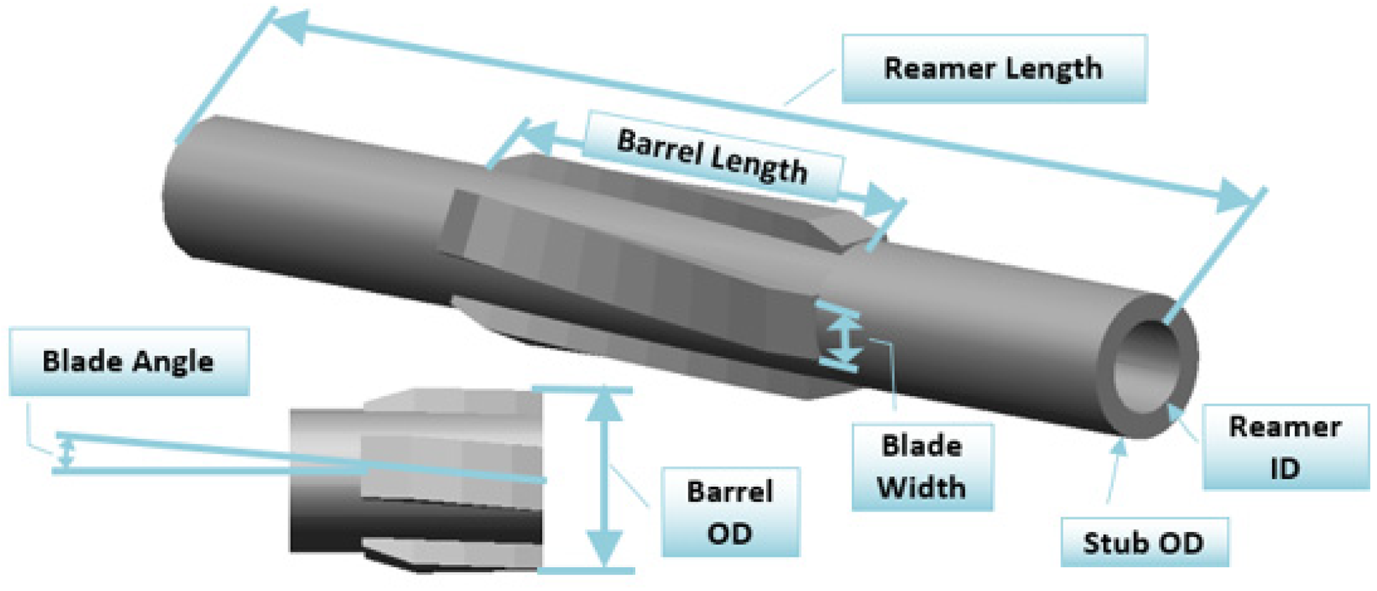
Reamer body model.


During reamer rock-breaking operations, the forces acting on the blades exhibit significant fluctuations. These fluctuations intensify substantially with reamer wear development. To simulate this oscillatory behavior, a fluctuating load function—which varies with the reamer rotation angle—is superimposed on equations (2)–(5), as given in equation (6).

WOB model
The WOB input is introduced into the hook load function via the STEP function (equation (7)). The hook load function (equation (8)) is defined as the summation of the WOB-based STEP function and the integral of the hook load differential function (equation (9)). Simultaneously, the hook load acts as the external load applied to the EUA dynamic model. The lower end of the EUA is coupled to the BHA through a spring-damper system.


ROP model
During rock-breaking operations, an axial load acts between the wellbore wall and the near-bit reamer. Simultaneously, spring and damping forces exist between the wellbore wall and the formation. Therefore, the ROP is simulated using a nonlinear spring-damper function. Based on Newton's second law of motion, the BHA dynamics governing equation is established.

Validity of the analysis model
Laboratory experiment
To validate the developed analytical model, laboratory experiments were conducted using a drill bit test rig. The test assembly consisted of a bit + instrumented sub + near-bit reamer + instrumented sub + drill collar. A homogeneous cement rock sample with a length of 800 mm was employed as the simulated formation. Testing parameters included a 10 kN WOB and 40 rpm rotational speed. The experimental setup is shown in Figure 4.

Laboratory experiment.
Figure 5 presents the analytical model validation results, with data from the stable drilling interval (400–600 mm) selected for comparative analysis. Experimental measurements yielded an average WOB of 8.45 kN with 8.44 kN RMS, while the model predicted 8.57 kN average WOB and 8.58 kN RMS. Both mean WOB error and WOB RMS error were 1.5%. For torque, experimental values were 339.35 N·m (average) and 339.66 N·m (RMS), versus model predictions of 348.54 N·m (average) and 348.21 N·m (RMS), resulting in 2.6% errors for both mean torque and torque RMS. Laboratory validation thereby confirms the model's effectiveness.
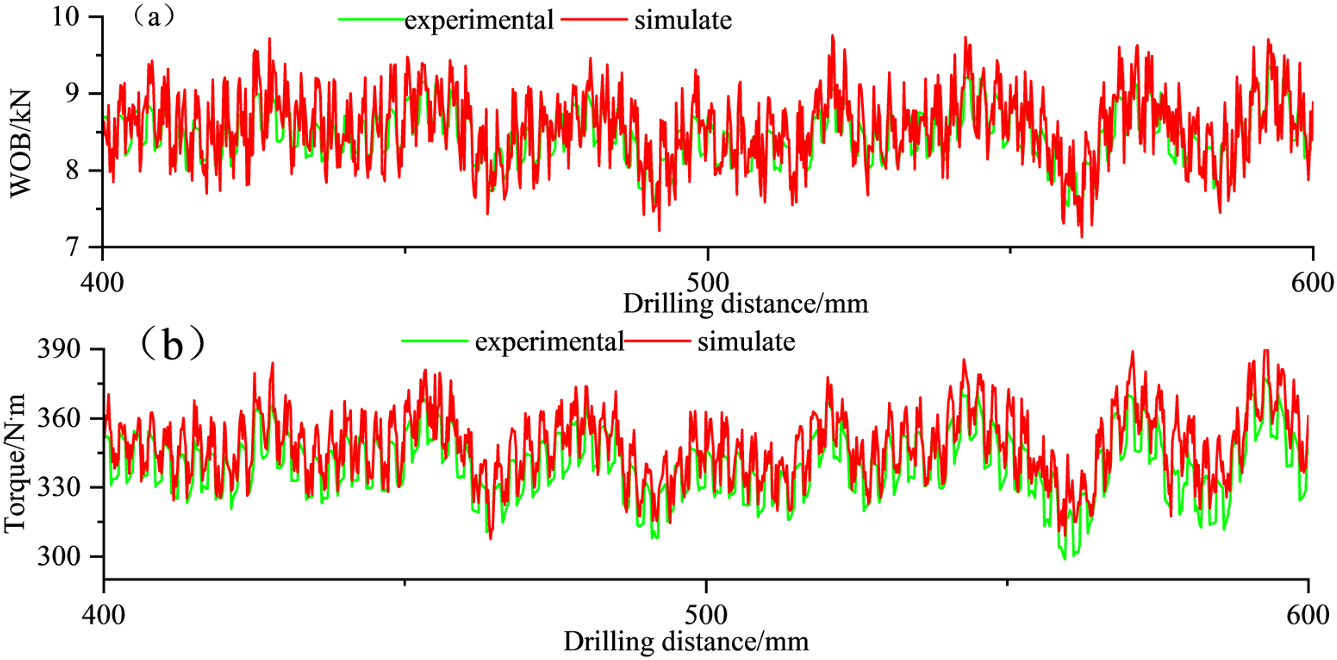
Analysis of model validation results: (a) WOB comparison and (b) Torque comparison.
Field experiment
Comparative analysis was performed using vibration data from a reaming operation in a well of Dagang Oilfield. The BHA comprised: pilot bit + double female sub + stabilizer + crossover sub + float valve + crossover sub + reamer + instrumented sub + 42 joints of heavy-weight drill pipe + 372 joints of drill pipe. Figure 6 illustrates the established BHA model, while Figure 7 presents a quantitative comparison between simulated and field-measured results.

Field experiment: (a) wellbore trajectory, (b) experimental reamer, and (c) BHA.
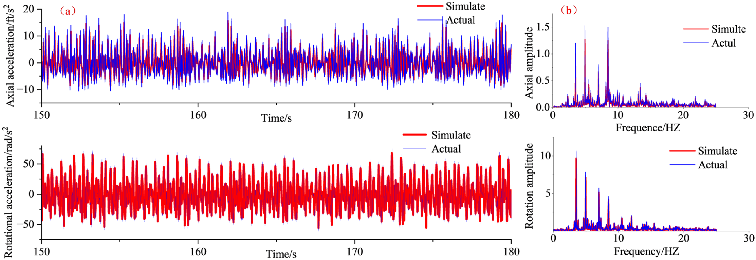
Comparison between simulated data and measured data: (a) time-domain plot and (b) frequency-domain plot.
The time-domain plot in Figure 7(a) shows that while there are discrepancies in the RMS values of the vibrational accelerations—specifically, 17% for the axial component (simulated: 0.126 g, measured: 0.152 g) and 9% for the torsional component (simulated: 23.860 rad/s2, measured: 26.247 rad/s2)—the dynamic response characteristics are highly consistent. The frequency-domain plot in Figure 7(b) demonstrates a high degree of consistency between the simulated and measured curves at major resonant peaks, notably around 4 and 8 Hz within the 0–10 Hz primary frequency band. This agreement effectively validates the model's accuracy in predicting the system's natural frequencies and confirms that the model accurately captures the system's dynamic characteristics.
These discrepancies are primarily attributed to two factors: (1) The model is designed to capture low-frequency global vibrations, whereas the measured signals contain high-frequency components induced by downhole tool joints, collisions, etc., which inflate the measured RMS values; (2) The nonlinear damping at the drill string-borehole wall/drilling fluid interface is difficult to quantify precisely, leading to deviations in amplitude prediction. Given the high complexity of downhole dynamic systems, the 9% error in torsional vibration is within an acceptable engineering range, and although the 17% axial error is larger, the model successfully captures its core dynamic characteristics. Therefore, the model is validated as effective and reliable for capturing the essential physics, providing a solid quantitative basis for evaluating the vibration suppression performance of stabilizers.
Analysis of vibration suppression effectiveness through stabilizer configuration optimization
Position of stabilizer
Figure 8 illustrates the stabilizer positioning configurations. Computational analysis of vibration responses (Figure 9) reveals significant differences among three scenarios: Scenario 1 exhibits the largest fluctuation range in axial acceleration (−1.5 to 4.5 ft/s2), while Scenarios 2 and 3 demonstrate distinct stabilization characteristics. Quantitatively, Scenario 2 achieves the minimum axial acceleration amplitude (0.0192 g) and RMS value (0.0059 g), representing 53.2% and 53.0% reductions compared to Scenario 1 (0.0126 g RMS) and Scenario 3 (0.0140 g RMS), respectively. For rotational acceleration, Scenario 2 similarly yields the lowest amplitude (36.108 rad/s2) and RMS value (14.264 rad/s2). Frequency-domain analysis demonstrates the critical influence of the stabilizer's axial installation position on the system's dynamics. Marked by pronounced resonance peaks near 8, 10, and 18 Hz, the axial amplitude spectra for the three configurations show significant variations in peak magnitude. Specifically, Scenario 1 produces the highest peak at 8 Hz, while Scenario 3 exhibits the minimum response throughout the 0–30 Hz band, underscoring its effective vibration suppression capability. Analysis of mass-center trajectories in the XY-plane (evaluated by 2D spatial dispersion) shows: Scenario 1 (red-solid line): Maximum distribution span (X: [−0.10, 0.10] ft; Y: [−0.08, 0.08] ft), Scenario 2 (blue-dashed line): Highest concentration in core zone (X: [−0.03, 0.03] ft; Y: [−0.02, 0.02] ft), Scenario 3 (green dash-dotted line): Intermediate distribution. Critically, Scenario 2 reduces trajectory dispersion area by 92.5% relative to Scenario 1 (calculated from rectangular domains), confirming its superior vibration suppression capability and dynamic stability.

Comparison between simulated data and measured data.

The influence of the position change of the stabilizer on vibration: (a) time-domain plot, (b) frequency-domain plot, and (c) centroid displacement.
Number of stabilizers
To investigate the influence of stabilizer number on reamer vibration intensity during near-bit reaming operations, five distinct BHAs were engineered (Figure 10). This experimental design enables systematic validation of vibration attenuation mechanisms governed by stabilizer count.
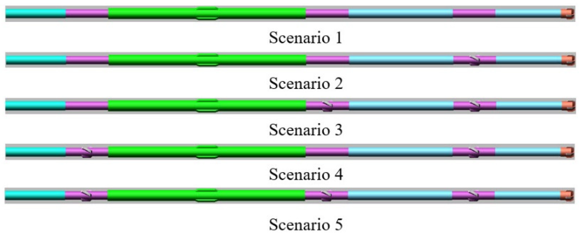
Number plan for stabilizers.
Dynamic analysis of five stabilizer configurations revealed significant variations in reamer vibration characteristics (Figure 11). Scenario 5 demonstrated the minimum vibration amplitudes, with RMS axial and rotational accelerations of 0.0085 g and 10.075 rad/s2, respectively. In contrast, Scenario 1 exhibited maximum vibration severity (0.0239 g axial, 30.416 rad/s2 rotational). Scenarios 2–4 displayed intermediate vibration levels. These results confirm that stabilizer number effectively modulates vibrational energy transfer. Frequency-domain analysis demonstrates the pronounced effect of stabilizer quantity on the system's vibrational response. Characterized by a dominant resonance peak within the 5–10 Hz range across all configurations, the results show that adding stabilizers significantly modifies the system dynamics. The dual-centralizer setup yields optimal suppression of the primary peak, achieving a 40% reduction in axial amplitude versus the centralizer-free baseline. A secondary harmonic near 8 Hz for the triple-centralizer case implies nonlinear behavior, whereas the quadruple-stabilizer configuration effectively confines energy in the 15–20 Hz band, highlighting its role in high-frequency attenuation. Thus, strategic selection of stabilizer count allows for tailored resonance control, with dual stabilizers targeting the fundamental mode and quadruple stabilizers extending the suppression bandwidth. Further assessment of mass-center trajectories quantified position-dependent stability impacts. Scenarios 1 and 2 showed concentrated trajectories within the upper-left quadrant (range: ±0.12 ft), exhibiting complex helical patterns with comparable displacement magnitudes. Comparative analysis revealed: Scenario 3 achieved optimal proximity to the coordinate origin, Scenario 4 formed large-scale circular distributions, while Scenario 5 developed distinct directional persistence within Scenario 4’s annular domain. Crucially, Scenario 3 exhibited the highest trajectory compactness, demonstrating superior capacity for constraining mass-center deviation and enhancing system stability.

The influence of the number change of the stabilizer on vibration: (a) time-domain plot, (b) frequency-domain plot, and (c) centroid displacement.
Stabilizer outside diameter
Figure 12(a) presents the vibration data of the hole opener corresponding to varying stabilizer outer diameters (ODs). The RMS value of axial acceleration decreased from 0.195 g at 204 mm OD to 0.087 g at 214 mm OD (a 55.4% reduction). Similarly, the RMS value of rotational acceleration decreased from 28.365 to 19.396 rad/s2 (a 31.6% reduction). Notably, when the OD exceeds 212 mm, the reduction magnitude for accelerations in all directions narrows to less than 5%, indicating the existence of an optimal OD threshold.

The influence of the OD change of the stabilizer on vibration: (a) time-domain plot and (b) frequency-domain plot.
Figure 12(b) clearly demonstrates the significant influence of the centralizer OD on the system's vibrational characteristics. In the axial amplitude spectrum, all curves exhibit distinct resonance peaks near 8, 10, and 18 Hz, indicating that these frequencies represent critical natural frequencies of the system. Specifically, the configuration with an OD of 208 mm produces the highest axial amplitude peak at 8 Hz, while the OD 214 mm configuration consistently exhibits the lowest resonant response across the primary frequency band observed (0–20 Hz), highlighting its superior vibration suppression capability. In the rotational amplitude spectrum, although the overall amplitude magnitude is relatively small, the OD 208 mm configuration similarly induces the most prominent peak near 8 Hz. This further confirms that smaller ODs may be more sensitive to excitations at specific frequencies, leading to amplified vibrations. In summary, increasing the centralizer OD effectively attenuates multiple resonance peaks by enhancing system stiffness and damping, providing a clear direction for optimizing dynamic performance and suppressing harmful vibrations.
Discussion
Figure 9 presents the analysis results concerning the influence of a single stabilizer's installation position on vibration, confirming that the stabilizer location is a critical parameter for suppressing the reamer's vibrations. Scenario 2 achieved the optimal performance by providing the most effective local rigid constraint and isolating the vibration coupling path. Specifically, Scenario 1 (above the drill bit) renders the reamer a low-stiffness cantilever beam, leading to large-amplitude vibrations. Scenario 3 (above the reamer) improves the stiffness to some extent, but the support below remains relatively weak. In contrast, Scenario 2 provides rigid support directly at the reamer's load-bearing source, forming a short-beam model analogous to a “fixed-pinned” boundary condition. This configuration minimizes the effective vibrational length of the system and significantly enhances radial stiffness. According to beam vibration theory, stiffness is inversely proportional to amplitude, which explains why Scenario 2 results in the centroid trajectory in the XY plane being highly concentrated within the core region, suppressing the centroid offset area by 92.5% compared to Scenario 1. Furthermore, reamer vibration is inherently a nonlinear coupling of lateral, axial, and torsional vibrations. In Scenario 1, lateral vibrations propagate freely and intensely excite axial fluctuations through geometric nonlinear effects (such as bending moment-induced variations in axial force), resulting in the largest range of axial acceleration fluctuation (−1.5∼4.5 ft/s2). The key advantage of Scenario 2 lies in the fact that the stabilizer below acts as a dynamic vibration isolation pivot. It not only restricts the transmission of vibrations to the upper drill string but, more critically, significantly suppresses the dynamic disturbance of the reamer's lateral oscillation on the WOB, thereby blocking the primary coupling pathway between lateral and axial vibrations.
Figure 11, which presents the analysis of stabilizer number effects on vibration, reveals that the mechanism by which an increasing number of stabilizers suppresses reamer vibration is not a simple linear superposition but is achieved by reconstructing the system's constraint network and force transmission path. The analysis indicates that the core role of increasing the number is to progressively alter the system's dynamic behavior, shifting it from “flexural beam” vibration towards “rigid body” vibration. The primary function of a single stabilizer (Scenario #2) is to establish a foundational constraint, transforming the system from an unconstrained “cantilever beam” model to a “fixed-pinned” model. This initially enhances stiffness and creates a vibration barrier, yet its direct stabilizing effect on the reamer itself remains limited. The effectiveness of two stabilizers is highly dependent on their placement, highlighting the synergy between number and position: Scenario #3 (one below the reamer and one above the bit) creates a locally rigid segment by employing two constraints, effectively “encapsulating” the reamer. This configuration minimizes the effective vibration length and reconstructs the force transmission path, enabling lateral forces generated by the reamer to be directly transferred to the borehole wall. Consequently, it efficiently blocks the primary coupling between lateral and axial vibrations, resulting in optimal centroid stability. In contrast, Scenario #4 (one above the reamer and one above the bit) demonstrates the consequence of suboptimal placement. While it increases the stiffness of the upper drill string, it fails to form an “encapsulating” constraint around the reamer. This leaves a flexible section below it, where vibrational energy can accumulate, leading to large-scale whirling motion. The triple-stabilizer configuration (Scenario #5), building upon an optimized layout, achieves global over-constraint, pushing the system stiffness to its maximum. This results in the globally lowest vibration amplitudes. The unique centroid trajectory observed in Scenario #5 indicates that its effect surpasses mere stiffness enhancement; it significantly alters the system's vibrational modes by “squeezing” the primary vibrational energy into higher-frequency modes that are more readily attenuated, thereby achieving an upgrade from amplitude suppression to modal control.
The data presented in Figure 12, showing pronounced vibration suppression with increased stabilizer OD, stems from a fundamental reshaping of the drill string system's dynamics. The decrease in radial clearance associated with increasing the OD from 204 to 214 mm initiates key synergistic mechanisms: The primary mechanism is a marked increase in system stiffness due to a transition from a statically determinate to a statically indeterminate configuration. A small-OD stabilizer allows a large clearance, causing the BHA to approximate a low-stiffness, statically determinate cantilever beam prone to large-amplitude vibrations under excitation. In contrast, a larger OD establishes effective contact with the borehole wall, introducing an additional constraint that creates a statically indeterminate structure. This significantly boosts lateral bending stiffness, raising the system's natural frequencies and shifting its dynamic response away from the predominant low-frequency excitation band to prevent resonance. A second critical mechanism is the establishment of a potent energy dissipation path via frictional damping. The enlarged contact area generates substantial Coulomb friction damping, positioning the stabilizer as an “energy sink” along the vibration transmission path. As vibrational waves encounter this high-damping interface, their amplitude is sharply attenuated through conversion to heat. This mechanism directly accounts for the substantial reductions in axial (55.4%) and torsional (31.6%) acceleration RMS values. The superior suppression of axial vibrations results from the direct constraint imposed on axial elastic wave propagation. Additionally, forced centralization enhances dynamic stability by suppressing whirl. Based on rotor dynamics theory, the added stable support raises the stability threshold, curbing this self-excited vibration source at its root.
This study aligns with the conclusions of References11,12 regarding the effectiveness of stabilizers in suppressing vibrations of reamers while drilling. However, there are fundamental methodological differences. References11,12 primarily rely on static or quasi-static local analyses conducted in Abaqus, which are limited in capturing the dynamic interactions of the drill string as a holistic downhole system and do not account for the influence of reamer wear under actual operating conditions. This work differs in two ways: first, by comparing vibration responses without stabilizers and under various stabilizer configurations, it systematically elucidates the vibration suppression mechanism and optimizes the placement strategy; second, it innovatively incorporates reamer wear as a fixed operational condition within the analytical framework, thereby enhancing the model's alignment with real-world scenarios and significantly improving the practical applicability of the findings. Consequently, this work advances the analysis of this issue from idealized local static simulations to a practical stage that integrates full-scale drill string dynamics with critical wear factors.
This study elucidates the synergistic mechanism by which the position, number, and OD of stabilizers suppress reamer vibrations, providing clear guidance for bottom-hole assembly (BHA) design. The core principles are defined as follows: position is the foundation, number is the upgrade, and OD is the amplifier. The optimal configuration should prioritize placing a stabilizer directly below the reamer to achieve “local rigidization,” effectively decoupling lateral-axial vibrations. Increasing the number of stabilizers extends this effect from localized “enveloping” stability to global “over-constrained” modal control, shifting vibrational energy into higher-frequency modes that are more readily attenuated. Meanwhile, increasing the stabilizer OD amplifies the damping effect by enhancing radial constraint and introducing Coulomb friction damping. For field application, a tiered optimization strategy is proposed: the “dual-stabilizer” configuration (above and below the reamer) balances cost and effectiveness for routine operations, while a “tri-stabilizer global rigidization” design is recommended in complex formations to mitigate extreme vibration risks. Consistently selecting large-OD, wear-resistant stabilizers is crucial to ensure sustained constraint and damping performance. This mechanism-driven design paradigm can significantly enhance drilling safety and efficiency.
Conclusion
This study developed and validated a multibody dynamics model for a reamer-while-drilling system based on an “EUA + BHA” approach. Its core innovation and contribution lie in establishing an analytical framework that incorporates the wear state of cutting teeth as a key variable, overcoming the limitations of traditional static mechanical analysis. Using a weighted factor equivalent method for the cutting teeth, the model enables the quantitative assessment of the macroscopic impact of wear on drill string vibrations. Furthermore, it reveals the synergistic vibration suppression mechanism of the stabilizer configuration, summarized as “position sets the foundation, number enhances control, and OD increases damping,” providing a crucial theoretical basis for optimizing vibration suppression strategies in engineering practice. It should be noted that this study primarily focuses on establishing and validating the feasibility of this analytical framework. The main conclusions obtained are as follows:
This study identified that the stabilizer position is the primary factor for vibration suppression, with the optimal layout (directly below the reamer) significantly reducing the centroid offset area by 92.5%. The research demonstrated that increasing the number of stabilizers is the core means to enhance vibration suppression effectiveness. Adopting a three-stabilizer configuration reduced axial and torsional vibrations by 64.4% and 66.9%, respectively. With dual stabilizers optimally suppressing the fundamental resonance and quadruple centralizers effectively broadening the attenuation bandwidth. The study verified that the stabilizer outer diameter serves as an important supplement for optimizing vibration suppression performance. Increasing the outer diameter from 204 to 214 mm resulted in further reductions of 55.4% in axial vibration and 31.6% in torsional vibration. The 214 mm configuration demonstrating superior vibration suppression across the frequency spectrum through enhanced system stiffness, whereas smaller diameters (e.g. 208 mm) tend to amplify vibrations at specific resonant frequencies.
The “Position-Number-Outer Diameter” synergistic vibration suppression design principle developed herein provides systematic theoretical support and quantitative operational guidance for vibration control in RWD tools, holding significant value for enhancing the safety and reliability of drilling engineering.
Scope
The wear coefficients used in the model are based on generalized assumptions, and the research does not yet systematically elucidate the full-cycle dynamic evolution from new blades to complete wear, representing a limitation of this work. Consequently, future research will focus on quantitatively investigating the influence of different wear states on vibrational behavior. Plans include conducting rock fragmentation experiments to meticulously study the interaction between various cutter shapes, rock types, and wear stages. This will ultimately extend the current analytical framework into a precise model capable of predicting the dynamic behavior of the drilling tool throughout its entire operational life.
Footnotes
Nomenclature
Author contributions
Fusheng Yu contributed to conceptualization, methodology, software, validation, and writing–original draft. Yuchun Kuang and Bin Li contributed to resources and data curation. All authors participated in the writing–review and editing and approved the final version.
Funding
The authors disclosed receipt of the following financial support for the research, authorship, and/or publication of this article: We acknowledge financial support from the National Major Science and Technology Project of China (2016ZX05038), Scientific Research Fund Project of the National Engineering Research Center for Oil and Gas Drilling and Completion Technology (F2023239), and Science and Technology Development Project of China National Petroleum Corporation (2022ZG06).
Declaration of conflicting interests
The authors declared no potential conflicts of interest with respect to the research, authorship, and/or publication of this article.
Data availability
The datasets used and analyzed during the current study are available from the corresponding author on reasonable request.