
Abstract
The grid-connected inverter is the key to ensure stable, reliable, safe, and efficient operation of the power generation system; the quality of the grid-connected output current waveform directly affects the performance of the entire power generation system. To improve the anti-interference performance and reduce the output current harmonic content of the grid-connected inverter, an improved control strategy that combined repetitive control (RC) and auto disturbance rejection control (ADRC) is designed in this paper. Firstly, decoupled the ADRC to realize the individual adaptation between tracking performance parameters and anti-interference performance parameters of the controller, through which the difficulty of adjusting parameters is reduced. Secondly, the control approach is devised by adding RC to ADRC. To demonstrate the effectiveness of the proposed method in this paper, detailed experimental studies are conducted using proportional integral control, traditional ADRC, and the proposed method under normal power grids, weak power grids, and periodic disturbances. And dynamic performance simulation experiment is done to verify the dynamic performance of the self-disturbance rejection controller before and after the addition of RC links. The results indicated the effectiveness and feasibility of the proposed method. Finally, after simulation, the steady state and dynamic performance are conducted on a hardware testing platform. The impacts of the obtained results indicate the effectiveness and feasibility of the control algorithm proposed, the ability to suppress intermediate frequency disturbances is improved, the bandwidth of the auto disturbance rejection controller is expanded, and the harmonic content of the output current is depressed.
Keywords
Introduction
Nowadays, the “dual carbon” green development goal proposed in China 2020 has received attention from various sectors at home and abroad. However, in the context of global energy scarcity, achieving the “dual carbon” goal is a transformative goal for the development of new energy.1,2 According to the national grid connection standards GB/T14549 and IEEE1547,3,4 the total harmonic distortion (THD) of electrical energy injected into the power grid must be less than 5%. However, because of the existence of nonlinear factors such as the dead time effect, switching tube conduction voltage drop, and grid voltage fluctuations in grid-connected inverter systems, it is difficult for inverters to maintain good performance; thus, the research on inverters is of great significance.5,6
At present, the main control strategies for grid-connected inverters include proportional integral (PI) control, proportional resonance (PR) control and repetitive control (RC). The PI controller has the advantages of simple design and easy parameter adjustment. So it is widely used in practical engineering.7–9 Although the PI controller can provide good performance in DC control applications and be able to achieve zero error tracking. But the tracking and control effects of communication signals are not ideal.10,11 Zhang et al. 12 adopted a feedback strategy for the grid-side current employing the PI and resonant controller to mitigate the harmonics of the grid-side current and improve the quality of the output power of the grid-connected LCL-filtered inverter, but this strategy can only improve the quality of grid-side current under non-ideal grid conditions. Ahmed et al. 13 used a simple PI controller-based approach to propose a method for improving the small signal dynamic response of a grid-connected SOFC plant where the controller parameters are adjusted by the DE algorithm. Aouchiche 14 adjusted the gain values of PI regulators in order to enhance the grid-connected system dynamic behavior, but it didn’t compare the performance of the FOPI and PI controllers. Elnady and Alshabi 15 suggested an adaptive PI controller, which has robust performance at different loading conditions, but is complex in its design procedure. Moeti and Asadi 16 proposed an adaptive PI current controller for a two-stage grid-connected photovoltaic inverter, which has the advantage of providing low grid current THD and desirable dynamic response, but it requires an accurate model of the system.
By setting the fundamental frequency point, the PR controller has sufficient gain at the fundamental frequency point while the gains at other points remain unchanged, thus achieving accurate and error-free tracking of the fundamental wave of the AC signal.17–20 But the control frequency band of the PR controller is narrow and it can only achieve sufficient gain at a fixed frequency. 11 Negi et al. 21 used the PR controller to realize an improved damping strategy that has enough stability margin, but requires an accurate model of the system and high online computational requirements. Yanarates and Zhou 22 designed a novel PR controller to resolve the drawbacks of conventional PI controllers in terms of phase management. Xie et al. 23 applied the PR controller to achieve a fixed switching frequency and mitigate steady-state error; however, it is not practical to implement by either analog or digital signal processors. Qiu et al. 24 and Sou et al. 25 adopted the improved quasi-PR controller, this control method can only achieve zero static error tracking for a single-frequency signal.
Haneyoshi T et al. applied an RC strategy based on the internal model principle to inverters. 26 RC has the advantages of strong robustness and high steady-state accuracy. At the same time, it not only achieves zero static error tracking in inverters but also eliminates disturbances. However, the RC control has poor dynamic performance when using a single RC due to the delay link in the internal model.27–29 Guo et al. 30 utilized a current controller which combined repetitive controller with PI controller, the proposed method can eliminate the effects of harmonics and reduce the net current harmonics. Zhang et al. 31 utilized the control strategy of parallel connecting RC control and PI, in which the RC control was used to suppress harmonics in the system and the PI control was used to realize fast dynamic performance. Mao 32 designed a compound control strategy for LCL to improve the compensation effect of harmonic current.
In order to solve the problem of grid-connected current control, a grid-connected current control strategy that combines auto disturbance rejection control (ADRC) and RC control was proposed in this paper. The designed method expands the bandwidth of the self-disruption rejection control and also has better dynamic performance; moreover, the anti-interference ability of grid-connected inverters can be effectively improved, and the output current harmonic content can be reduced. In addition, periodic disturbances can be effectively suppressed.
The remaining structures of the article are arranged as follows: The theoretical basis for the design of grid-connected inverters is analyzed in Section Related Work. The design methods are proposed in Section Methods. Section Experiment methodology and results presented the simulation and experimentation. The experimental conclusions and future research are presented in Section Conclusion.
Related work
Analysis of the structure and working principle of grid-connected inverters
The topology structure of a single-phase LCL grid-connected inverter is shown in Figure 1. Udc is the DC bus voltage, S1∼S4 is the switching,

Topology structure of a single-phase LCL grid-connected inverter.
To facilitate the analysis of the working principle of the LCL grid-connected inverter, the following assumptions need to be made:
The switching devices in the circuit are all ideal devices; the voltage drop and switching time during IGBT conduction are negligible. The circuit characteristics are ideal; there are no parasitic circuits, distributed inductance, or capacitors. The DC side voltage is in a stable state.
In the modulation method of the SPWM wave, the unipolar frequency doubling method is selected to control the turn on and off of the switch tube. The modulation principle is shown in Figure 2. Where

Unipolar frequency doubling modulation.
Analysis of LCL filter characteristics
The equivalent circuit diagram of the inverter is shown in Figure 3.

Equivalent circuit diagram of the inverter.
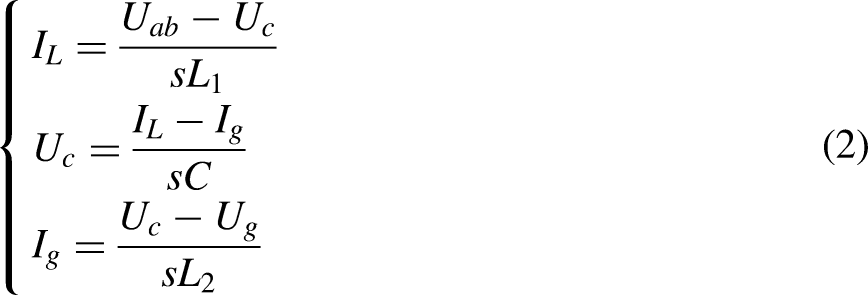
According to Kirchhoff's current law, the equation of the filter can be written as follows:
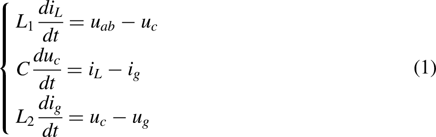
By applying the Laplace transform to the above equation, it can be obtained that:

Control block diagram of an LCL grid-connected inverter.
According to Figure 4, the transfer function from the output side voltage


If the capacitance C is equal to 0, the LCL-type filter will become an L-type filter, and the transfer function is as follows:

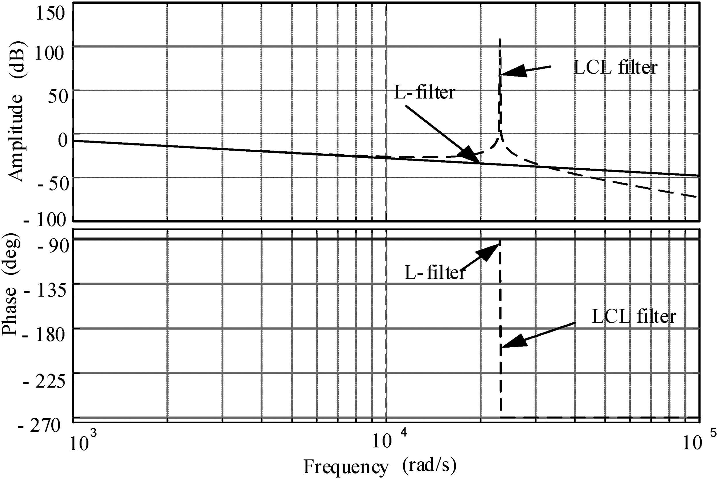
Bode diagram of LCL filter and L filter.
If we only consider damping from the perspective of parallel resistors at both ends of the capacitor, they will have the best damping effect. However, from the circuit perspective, the voltage at both ends of the damping resistor is the grid voltage, which can cause significant power loss on the resistor. So, comprehensive power loss, filtering characteristics, damping characteristics, and control methods. This article adopts the method of connecting resistors in series at both ends of the capacitor, as shown in Figure 6. This method has low power loss, a simple structure and is widely used in industry.

Capacitor C series resistance.
According to Figure 6, it can be inferred that the transfer function from output voltage

Analysis and design of an active disturbance rejection control strategy
The core idea of active disturbance rejection control technology is to simplify complex systems into integral series systems and treat all parts outside the integral series system as total disturbances; then, through expansion, the observer performs real-time estimation and compensates for the total disturbance. Due to the complexity of nonlinear structures and the difficulty of parameter tuning in practical applications, it is difficult to achieve in engineering. At the beginning of this century, Dr Gao Zhiqiang proposed linear auto disturbance rejection control (LADRC), which is based on the concept of frequency scale and improves and simplifies nonlinear auto disturbance rejection technology, the transition process of tracking differentiators is omitted, feedback error control rate is associated with extended observer and frequency bandwidth, the control structure is simpler, and the control performance is also better. Compared with the PI controller, LADRC has stronger suppression capabilities for high-frequency noise and low-frequency disturbances, and it can avoid overshoot of step signals.33,34 Therefore, it is widely used in industrial control scenarios such as aircraft control, ship control, and motor control.
Linear expansion observer
The linear expansion observer (LESO) is capable of real-time estimation and compensation of the total disturbance of the system. When the extended observer can accurately estimate disturbances, the system is compensated as a series integral type and achieves control over expected indicators through simple control rates.
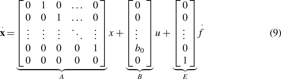
For n-order controlled objects:


With the goal of building an integral series system, f is added to the extended observer to form a new state for estimation and compensation. If

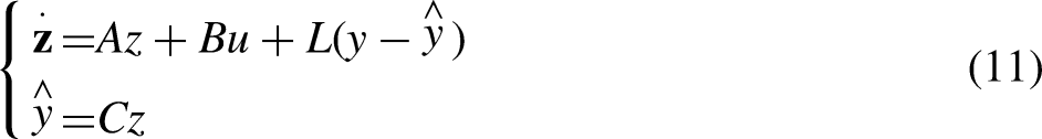
Disturbance compensation
LESO estimates the total disturbance and implements compensation. Finally, the system is calibrated as an integral series system to enhance its stability. The system disturbance compensation is as follows:

Substitute Equation (12) into Equation (8):

From Equation (13), it can be seen that if the disturbance of the system is observable, the system can be approximated as an integral series type. Namely, a structure composed of an integrator and a series of connected dynamic systems, this representation is very useful for designing controllers to resist the influence of disturbances.
Linear error control rate
When the system structure is an integral series type, superior control effects can be achieved with a simple linear error controller. The linear error control rate can be presented as follows:

Where r is the given reference value, and
For the n-order control system, the structural block diagram of linear auto disturbance control is shown in Figure 7.

Block diagram of n-order automatic disturbance rejection control.
Design of an active disturbance rejection controller for grid-connected inverters
According to the analysis in Section 2.3, the transfer function of the grid current to the output voltage of the inverter is as follows:


Bode diagram of the transfer function.
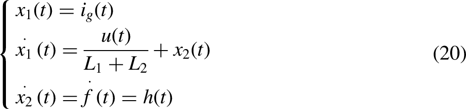
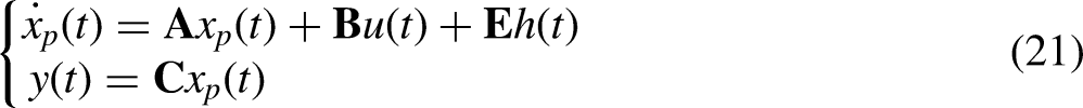
The transfer function from the grid-connected inverter's input current to the inverter side voltage after order reduction processing is as follows Equation (12). According to the above equation, the differential of the incoming and outgoing network currents is derived as follows:


Let


ADRC control block diagram of the LCL grid-connected inverter. ADRC: auto disturbance rejection control.
In order to make the expanded state observer estimate the total disturbance accurately and compensate for the total disturbance in real time, the observer bandwidth
Methods
Improved optimization design of auto disturbance rejection control
Analysis of the coupling problem of the active disturbance rejection controller
When auto disturbance rejection controllers are applied, if the tracking performance of the controller is only related to the control rate, and the anti-interference performance is only related to the extended observer, then the structural design of the auto disturbance rejection controller will be simple, and the parameter adjustment will be easy. But there is a coupling problem between the anti-interference performance and tracking performance parameters of LADRC. The parameter coupling problem of the controller will be explained through the following formula derivation.
For first-order auto disturbance rejection, the relationship between the estimated value of the system state variable u and the control variable and the system output
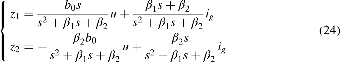
Bring the first equation of the above equation into the LSEF expression Equation (22) of the LCL grid-connected inverter, the expression for the output quantity


Block diagram of ADRC. ADRC: auto disturbance rejection control.
Where:


Design of decoupling linear auto disturbance rejection controller
To solve the problem of parameter coupling between the tracking performance and disturbance rejection performance of the auto disturbance rejection controller by compensating for the disturbance of the controller and changing the feed-forward channel to achieve decoupling of the extended observer, the decoupling active disturbance rejection control structure diagram is shown in Figure 11. After decoupling, the controller has stronger anti-interference performance against low-frequency and DC disturbances.

Decoupling ADRC structure diagram. ADRC: auto disturbance rejection control.
The decoupled extended state observer is as follows:


Analysis of decoupling LADRC immunity performanceAccording to the analysis in the previous section, the disturbance transfer function after decoupling the auto disturbance rejection controller is as follows:


Frequency domain characteristic diagram of the decoupling ADRC disturbance term. ADRC: auto disturbance rejection control.
When the system signal is a step signal, the anti-interference ability of the decoupled ADRC can be obtained from Equation (35); the steady-state error of the system disturbance output is as follows:

Design of RC structure
For a stable closed-loop system, if a repetitive controller is directly added to the control loop, theoretically, zero static error tracking can be achieved, but this control model will add N poles on the unit circle to the system. According to the Nyquist criterion, the open-loop system will be in a critical stable oscillation state, as long as there is a slight change in the system model parameters, the poles of the closed-loop system will fall outside the unit circle, causing the instability in the system. Therefore, when designing RC algorithms, it is usually necessary to make some changes to the ideal intima, using
The improved intima transfer function is as follows:


System diagram of RC. RC: repetitive control.
Where

Design of RC-ADRC for grid-connected inverters
To suppress non-periodic and periodic disturbances in grid-connected current, this paper adopted RC-ADRC. This method differs from traditional ADRC in the following two aspects: first, the expansion observer used in ADRC is a decoupled expansion observer, which is capable of decoupling the tracking performance and anti-interference performance of auto disturbance rejection; second, RC parallels the error control rate of self-disturbance rejection, which expands the bandwidth of the ADRC rate and can effectively suppress intermediate frequency disturbances. The extended observer of the decoupled controller can not only suppress constant disturbances but also compensate for the effects of parameter perturbations on the grid-connected inverter. The control structure diagram is shown in Figure 14.
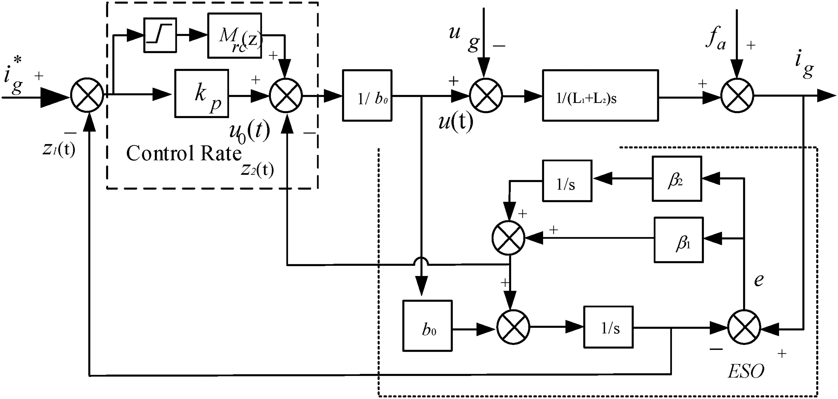
RC-ADRC control structure diagram. ADRC: auto disturbance rejection control; RC: repetitive control.
Because RC is generally designed in the discrete domain, the duty cycle of PWM interrupt updates in the discrete domain is not updated in real-time, but calculated in the previous cycle, so considering the delay of one sampling period. According to the ADRC model of the inverter in Equation (22), after adding a sampling period delay, the equation of control current of a grid-connected inverter under discretizing conditions can be obtained as follows:

According to Equation (39), add a time delay of one cycle to the extended observer, the extended observer for RC-ADRC can be designed as follows:

The control rate of RC-ADRC can be designed as follows:


From the above equation, it can be seen that the dynamic process of RC-ADRC is determined by both the ADRC rate and the repetitive controller, in order to avoid mutual influence between the two, the proportional component should play a dominant role in the dynamic process of the system, while in a stable state, the repetitive controller should play a dominant role; in this way, a better control effect can be achieved.
Stability analysis of RC-ADRC decoupling extended observer
The current loop error transfer function based RC-ADRC can be calculated by Equations (39) and (40).


Jury table.

The necessary and sufficient conditions for the stability of the extended observer based on the Jury criterion are as follows
36
:


Experiment methodology and results
Simulation of grid-connected current control
Simulation of normal grid-connected current control
To verify the application of the designed controller in the LCL grid-connected inverter, the following is a comparative analysis of PI control, ADRC and RC-ADRC for the grid-connected current in the grid-connected power generation system using simulation software. The parameters designed for the grid-connected inverter are as follows: the discrete step size is 1e-6s, and the frequency of PWM is 20 kHz. The PI controller parameters are set as follows: proportional coefficient Ka = 80; integration coefficient Ki = 10. The parameters of the traditional ADRC are set as b0 = 121.951; Kp = 1200; ωo = 3600;The parameters of RC-ADRC are set as follows: Q(z) = 0.95; k = 5;
Firstly, simulation comparisons were conducted under the condition that all parameters of the grid-connected inverter were standard parameters. The grid-connected current waveform and THD are shown in Figures 15, 16, and 17.

Pi control of grid-connected current waveform and THD analysis. THD: total harmonic distortion.

Traditional ADRC grid-connected current waveform and THD analysis. ADRC: auto disturbance rejection control; THD: total harmonic distortion.

RC-ADRC grid-connected current waveform and THD analysis. ADRC: auto disturbance rejection control; RC: repetitive control; THD: total harmonic distortion.
From the above figure, it can be seen that the RC-ADRC strategy has a good ability to suppress voltage disturbances in the power grid and can make the incoming current have better waveform quality. When using the PI control strategy, the THD of the incoming current is 2.54%; when using the ADRC strategy, the THD of the incoming current is 1.84%; when using the improved RC-ADRC strategy, the THD of the incoming current is 1.48%. It can be seen that the application of improved ADRC to grid-connected inverters is feasible.
Simulation of weak grid-connected current control
The current waveform of three control strategies in weak current networks is shown in Figures 18, 19, and 20, from the figure, it can be seen that the THD value of the grid connected in the weak current grid state is better than that in the normal grid, this is because, under weak current network conditions, the inductance present in the power grid increases the filtering inductance on the grid side of the grid-connected inverter, thereby improving the filtering effect. But comparing the three different control strategies, the designed RC-ADRC strategy can still maintain a good control effect in weak current networks.

Analysis of the current waveform and THD using PI control in a weak grid. THD: total harmonic distortion.

Analysis of the current waveform and THD using ADRC control in a weak grid. ADRC: auto disturbance rejection control; THD: total harmonic distortion.
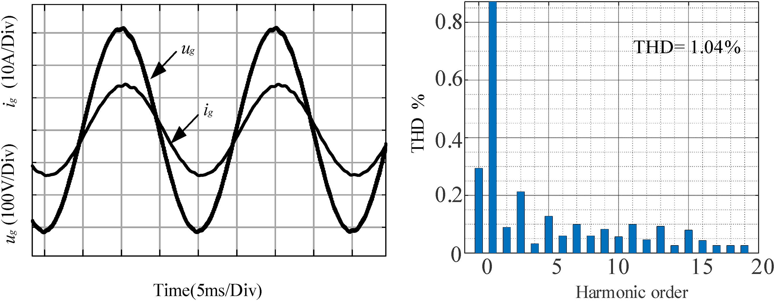
Analysis of the current waveform and THD using RC-ADRC control in a weak grid. ADRC: auto disturbance rejection control. RC: repetitive control; THD: total harmonic distortion.
Grid-connected current periodic disturbance experiment
To verify the controller's ability to suppress periodic disturbances, varying degrees of 3rd, 5th, 7th, 9th, and 11th harmonics are simultaneously injected into the grid voltage, then simulating and verifying the auto disturbance rejection controller before and after adding RC. The simulation waveforms of traditional ADRC and RC-ADRC are shown in Figures 21 and 22, from the figure, it can be seen that adding RC to the ADRC has a better suppression effect on periodic disturbances, and its output current waveform THD is lower, indicating that adding RC to the ADRC can suppress periodic disturbances.

Traditional ADRC current waveform under periodic disturbance. ADRC: auto disturbance rejection control.

RC-ADRC current waveform under periodic disturbance. ADRC: auto disturbance rejection control; RC: repetitive control.
Dynamic performance simulation
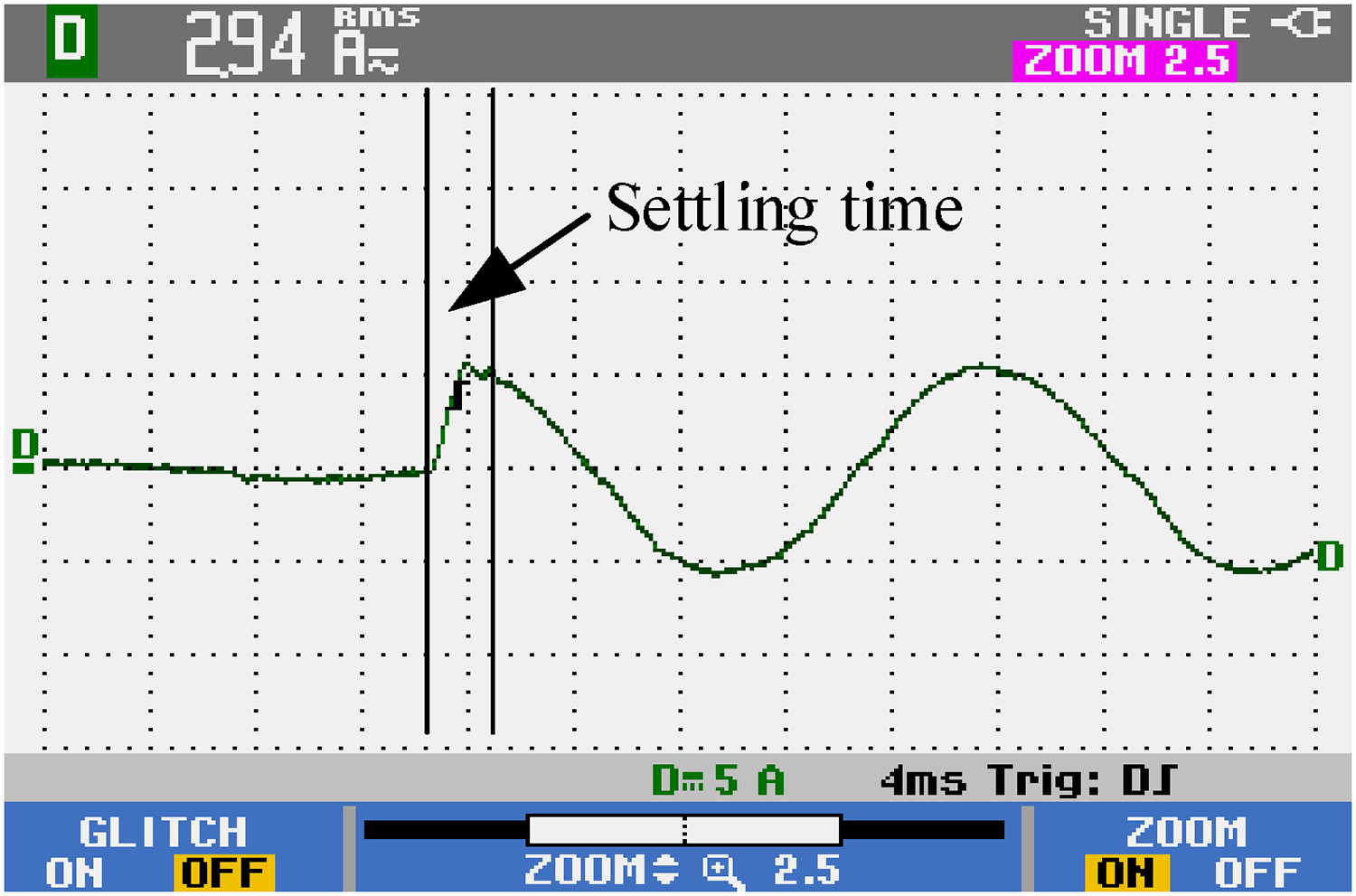
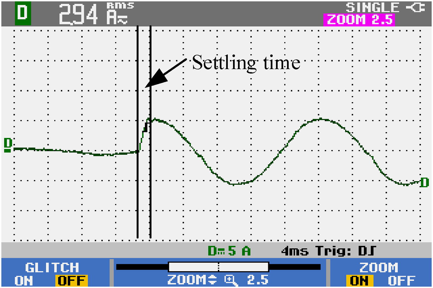
To verify the dynamic performance of the ADRC after adding RC links, an off grid inverter is used. As shown in Figure 23, when a sudden load is applied to an inverter of different control strategies with the same other parameters at 0.3s, the current dynamic response time of RC-ADRC is 3.014 ms, while the current dynamic response time of traditional ADRC is 4.410 ms, which proved that the improved auto disturbance rejection has advantages in dynamic performance.
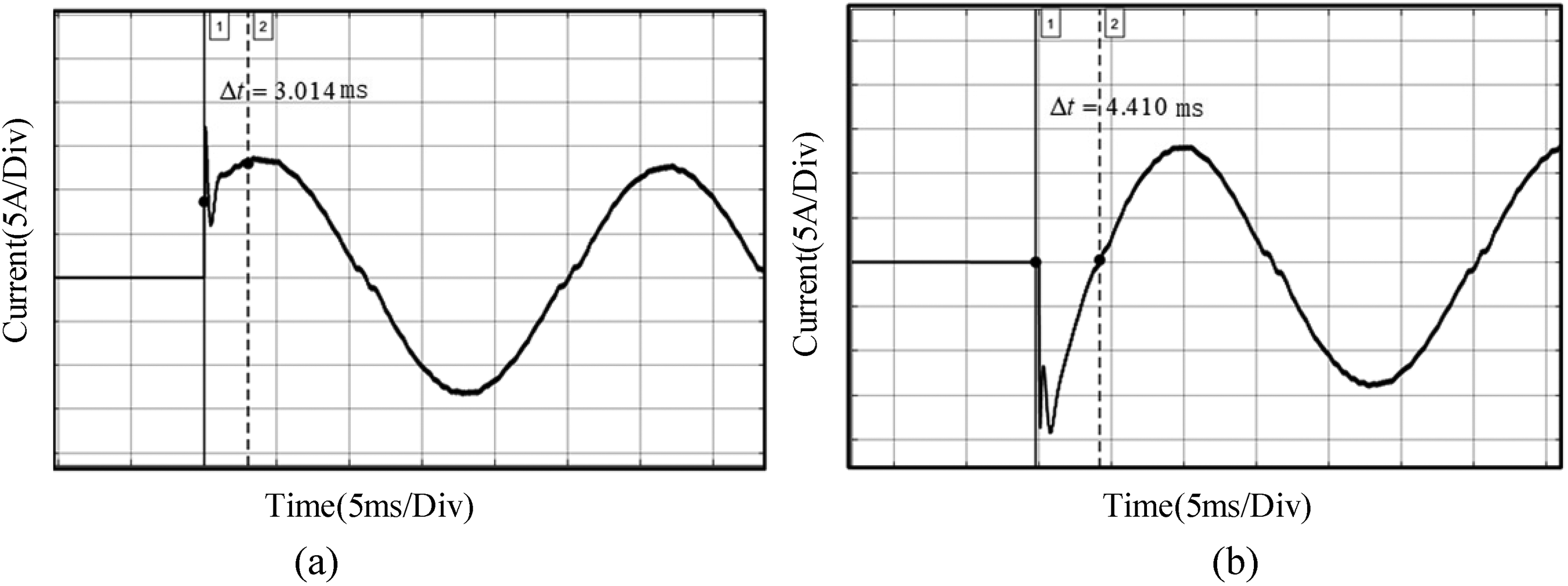
Current control dynamic response time. (a) Current dynamic response time of RC-ADRC (b) Current dynamic response time of traditional ADRC. ADRC: auto disturbance rejection control. RC: repetitive control.
Grid-connected current control algorithm experiment
Software design
The simulation in this paper was conducted using Matlab/Simulink software. The overall software model is shown in Figure 24, which is composed of an initialization program module, PWM output, and control system interrupt module. The interrupt module is shown in Figure 25, which mainly consists of signal extraction, SOGI phase-locked loop, control algorithm, and ePWM generation module. The specific execution of the program is as follows: Set the CPU interrupt to 3 in the Interrupt module, the PIE interrupt corresponding to 1 is an ePWM interrupt, when an ePWM signal occurs, the program will enter the interrupt program for execution; at this moment, the ADC collects signals, processes the collected voltage and current signals, and sends them into different AD channels. The A/D acquisition unit in the chip extracts the phase angle of the collected voltage signal through the SOGI phase-locked loop module and uses the obtained phase signal as a phase reference for the current signal, furthermore, PI, RC, and active disturbance rejection control are applied to the grid-connected current, and the signal after being standardized by the controller is sent to the ePWM module to control the switch transistor.

Overall structure diagram of code generation.

Model of control strategy execution program.
Experimental hardware design
The experimental platform built in this article is shown in Figure 26. The entire experimental platform consists of the collection section, the driving section, the power conversion section, and the controller. The voltage Hall model selected for the sampling circuit is TBV5/25A, with a range of ±700 V and a collection accuracy of 0.5%. The current Hall model selected for the sampling circuit is QBC15LX, with a range of ±10 A and a collection accuracy of 0.7%. The sampling circuit sends the collected voltage and current signals to the controller, which uses TMS320F28335 + AD7606 as the control unit. AD7606 is a 16-bit high-precision acquisition chip, and there are two options for input signal size: ±5 V and ±10 V. The collected signals of this chip can be directly fed into the module, eliminating the need for conditioning circuits. The main parameters of the experiment are shown in Table 2.

Physical diagram of the experimental platform.
Experimental platform parameters.

Waveform analysis of grid-connected current experiment
During the experiment, due to the fact that the grid voltage is connected to the inverter output side through a voltage regulator, the regulator itself has an inductance; moreover, the waveform of the power supply after passing through the voltage regulator is not so stable. Therefore, this experiment does not conduct waveform analysis under weak current networks, only compares the control strategies. The waveforms are shown in Figures 27 and 28.

Traditional ADRC current waveform and THD analysis. ADRC: auto disturbance rejection control; THD: total harmonic distortion.
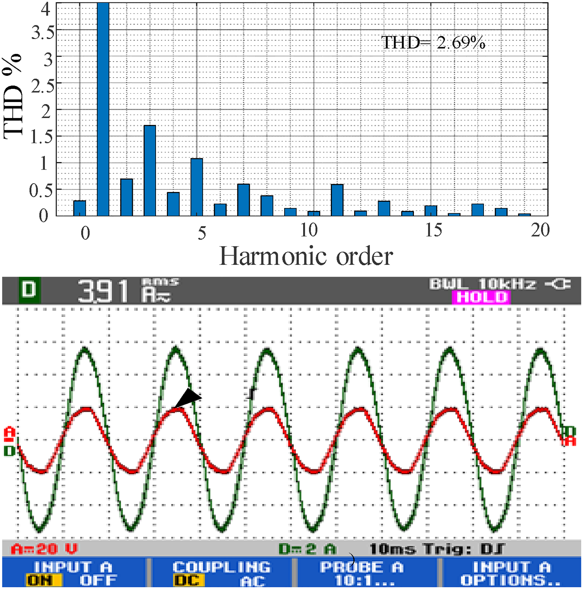
RC-ADRC current waveform and THD analysis. ADRC: auto disturbance rejection control; RC: repetitive control; THD: total harmonic distortion.
From the figure, it can be seen that when the given peak current is 6 A, the effective value of the output current is 3.91 A, and there is no difference in output accuracy between the two control methods. However, when analyzing the current THD, the harmonic suppression effect of RC-ADRC is better than that of ADRC, which indicates that the application of ADRC in grid-connected inverters has a great advantage.
Due to the fact that the design of RC is incorporated into the tracker of ADRC, therefore, in the experiment, the dynamic performance of adding RC that affects auto disturbance rejection was experimentally verified; the output waveforms are shown in Figures 29 and 30.
Dynamic response of traditional ADRC. ADRC: auto disturbance rejection control.
Dynamic response of traditional RC-ADRC. ADRC: auto disturbance rejection control; RC: repetitive control
As shown in the above figure, when the given value of the incoming current suddenly changes from 0A to a peak value of 5A. The adjustment time of traditional ADRC is 0.24 ms; however, the automatic disturbance rejection adjustment time with the addition of RC is 0.16 ms, it can be seen that adding RC has a positive effect on dynamic performance.
Conclusion
This article presents the current control problem of grid-connected inverters and proposes a RC-ADRC strategy to control the grid-connected current. By optimizing the structure of the extended observer, decoupling the tracking and disturbance rejection performance of the active disturbance rejection controller is achieved. Simultaneously incorporating RC into the control rate stage of ADRC. And conduct simulations and experiments on grid-connected control that focus on research and compare the control effects of different control strategies.
The reduction of grid-connected current THD is of great significance for the research of the entire system. In the simulation of normal grid-connected current control, the THD of the grid-connected current is 1.48% when the improved self-disruption rejection combined with RC scheme is adopted, which is better than the THD value when using the PI control strategy and the ADRC strategy. In the simulation of weak current grid-connected current control, the THD obtained by using the strategy designed in this paper is 1.04%. The THD of the current waveform under RC and active disturbance rejection control under periodic disturbances is 3.56%, which is better than the self-disruption rejection without RC in suppressing periodic disturbances. In the dynamic performance simulation experiment, the current dynamic response time of the control strategy designed in this paper is 3.014 ms. The waveform analysis of the grid-connected current experiment shows that the THD using the method in this paper is 2.69%. The experimental results show that the adopted RC-ADRC strategy has better dynamic performance and lower current THD.
This article adopts RC based on the internal model principle as an improvement component of the control rate, but the design of RC is relatively complex. The subsequent research can consider combining control algorithms based on other internal model principles to make controller design simpler.
Footnotes
Declaration of conflicting interests
The author(s) declared no potential conflicts of interest with respect to the research, authorship, and/or publication of this article.
Funding
The author(s) received no financial support for the research, authorship, and/or publication of this article.
Author biographies
Xixi Han holds a master's degree in Electrical Engineering. Her area of research is electrical control and smart power grid.
Bowen Xu is a postgraduate in Electronics. His area of research is electrical machinery and power electronics.
Keqi Kang is a postgraduate in Electrical Engineering. His area of research is modeling and control of power electronic systems.
Songwei Zuo is a postgraduate in Electrotechnics. His area of research is new energy power generation and grid connection.