
Abstract
Synchronous control is a fundamental and significant problem for controlling a multi-joint robot. In this article, by applying two coupled Rayleigh oscillators as the referred central pattern generator models for the two joints of a two-degrees-of-freedom robot, the central pattern generator–based coupling control method is proposed for controlling the two-degrees-of-freedom robot’s joints. On these bases, the co-simulation model of the two-degrees-of-freedom robot with the proposed central pattern generator–based coupling control method is established via ADAMS and MATLAB/Simulink, and the performance of the central pattern generator–based coupling control method on synchronizing two motions of two-degrees-of-freedom robot’s joints is numerically simulated. Furthermore, the experimental setup of a two-degrees-of-freedom robot is established based on the real-time simulations system via the proposed central pattern generator–based coupling control method. And experiments are carried out on the established setup. Simulations and experimental results show that the phase of the controlled two-degrees-of-freedom robot’s joints is mutual locked to other, and their motion pattern can be adjusted through the coupling parameter in the central pattern generator–based coupling control method. In conclusion, the proposed central pattern generator–based coupling control method can control the two-degrees-of-freedom robot’s joints to produce the coordinated motions and adjust the rhythmic pattern of the two-degrees-of-freedom robot.
Introduction
In the last decades, two-degrees-of-freedom robots (TDFRs) are widely applied for imitating the motions of the natural creatures with multi-joints whose rhythmic motions depend on the synchronized locomotion of their joints.1–5 Therefore, to imitate coordinated swinging or walking of the multi-joints natural creatures, each joint of the TDFRs needs to be movement synchronized with other coupled joints. Consequently, the synchronized control is a fundamental problem in the research of the bionics, which is worth focusing on. 6
Currently, the widely applied control methods for multi-joint robots include sliding mode control, 7 fuzzy control, 8 crossing-coupling control and contour error coupled control,9–11 and central pattern generator (CPG) control.12–19 Kamal et al. 7 controlled TDFR’s two joints to follow the two desired trajectories by applying the sliding mode control method. Combining proportional–integral–derivative (PID) control and fuzzy control, Mohan et al. 8 controlled a TDFR to achieve the pre-appointed motions. Zhang et al. 9 applied the crossing-coupling method to improve the synchronous errors of the sliding mode control method for a multi-motor system. Applying the crossing-coupling method to pre-compensate the contour error for the fuzzy PID control method, Liu et al. 10 and Lee et al. 11 reduced the tracking error and contour error for a three-axis machine tool. According to the neural biology of the rhythmic movement, Nandi et al. 12 , 13 proposed the swing control method to the lower limb prosthesis based on the Rayleigh oscillator–based CPG model. Torrealba et al. 14 proposed a method for controlling the knee prosthesis to cooperate with the sound knee. Fang et al. 15 proposed a new approach for the control of metameric robot locomotion via the phase coordination of a CPG model. Fu et al. 16 designed a nonlinear oscillator with the asymmetrical time ratio and discussed the synchronous of two coupled oscillators. de Pina Filho et al. 17 established a CPG model for a three degree-of-freedom (DOF) robot via the Rayleigh oscillators and discussed its synchronous. Yu et al. 18 proposed a motion planner via the van de Pol oscillators to generate the desired motions for a hexapod robot. Then, they applied a joint-space tracking controller to force the joints of the hexapod robot to track these desired motions. By employing two coupled MLMP (multi-layered multi-pattern)-CPG models (proposed by Nassour in 2014), Atoofi et al. 19 generated the synchronous motions of the shoulder joint and the elbow joint of a NAO robot to complete the drawing task.
Sliding mode control methods and fuzzy control methods both control each joint of the multi-joint robots to follow the specific referred trajectories, so they have the worse abilities on the synchronous controlling. Although crossing-coupling control and contour error coupled control methods have better abilities on the synchronous controlling, they are bad at adjusting locomotion patterns of robots. CPG control methods, which apply the CPG models to generate the referred trajectories and apply extra trajectory tracking control laws to track these generated referred trajectories, are complicated because of their utilized extra tracking control laws.
To overcome the drawbacks of these mentioned control methods and to synchronously control TDFR’s two joints, utilizing two coupled Rayleigh oscillators with the mutual locked phases as the referred models of the two joints, the CPG-based coupling control (CPGCC) method is proposed. On these bases, the co-simulation model of the TDFR with the proposed CPGCC method is established via ADAMS and MATLAB/Simulink, and the performance of the CPGCC method on synchronizing two motions of TDFR’s joints is numerically simulated. Furthermore, the experimental setup of a TDFR is established based on the real-time simulation system via the proposed CPGCC method. And experiments are carried out on the established setup.
Dynamical modeling of the TDFR
Conventionally, a TDFR can be simplified as a two-linkage mechanism with two rigid bodies and two joints, which is attached on a base as shown in Figure 1. Observing Figure 1, the linkage AB with its mass center of

where


where

Structural principle of TDFR.
According to equation (1), the state space models

and

where
To generate the synchronous motions of the linkages AB and BC, the models
Control method for the TDFR
In this section, via the coupling terms, two Rayleigh oscillators are coupled with the same frequencies and locked phases for imitating the motions of the TDFR’s two joints. In addition, using these coupled Rayleigh oscillators as the referred models, the CPGCC method is proposed to synchronously control the TDFR’s two joints.
Principle of the coupled Rayleigh oscillators
The Rayleigh oscillator, which is a second-order nonlinear dynamic system with a limit cycle, is expressed as15–17

where
For convenience, the Rayleigh oscillator given by equation (4) can be rewritten as a state space model expressed as
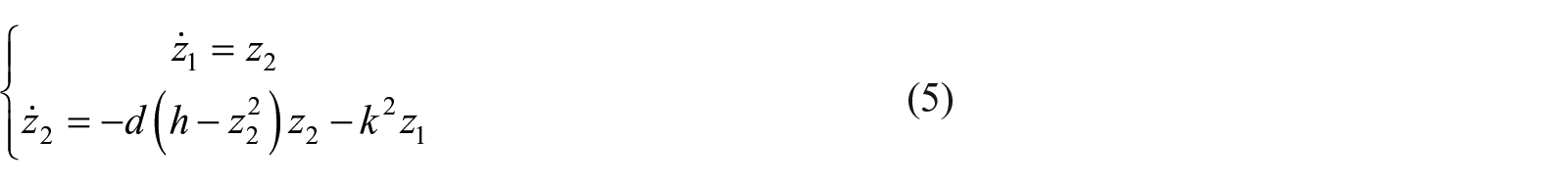
where
Adding the coupling terms

where
According to the works published in de Pina Filho et al., 17 the two Rayleigh oscillators with the coupling terms given by equation (6) are coupled to each other with the same frequencies and locked phases.
CPG model–based control method for the TDFR
The proposed CPGCC method applies the limit cycle of the Rayleigh oscillator to restrain interference and applies the locked phases of the coupled Rayleigh oscillators to synchronize the motions of TDFR’s two joints.
Figure 2 shows the control block diagram of the proposed CPGCC method. As shown in Figure 2, each joint of the TDFR is controlled by one control loop which includes the linearizer, the Rayleigh oscillator, and inverse DC model. The two coupled Rayleigh oscillators are used to generate the periodically oscillated deviations

Control block diagram of the TDFR with the proposed CPGCC method.
Defining the swing angle deviations of the joints relative to the zero position as

where
When the torques
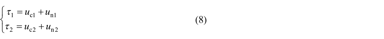
where


The dynamical error models of the joints of the TDFR can be expressed as

Substituting equations (7)–(9), we have

Observing equations (6) and (10), the dynamical error models of the TDFR shown in Figure 2 are two coupled Rayleigh oscillators. In conclusion, it is obvious that the movements of the joints of the TDFR with the torques given by equation (8) are coupled to each other similar to two coupled Rayleigh oscillators.
Numerical simulations and analyses
In this section, the TDFR with the proposed CPGCC method is simulated, and the synchronization of the two joints controlled by the proposed method is analyzed.
Simulation model
Figure 3 shows the simulation model of the CPGCC method established in Simulink. In Figure 3, the symbols theta1 and theta2 represent the swing angles
Structural parameters of the TDFR.

TDFR: two-degrees-of-freedom robot.
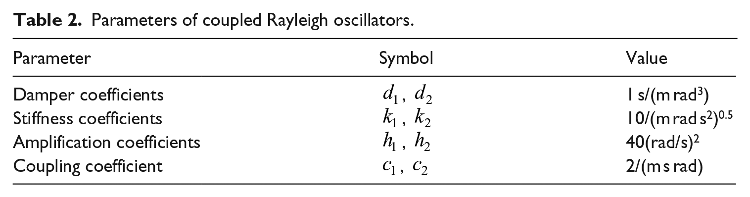
Parameters of coupled Rayleigh oscillators.

Simulation model of the TFDR with the CPGCC method.
Simulation results and analyzing
Behaviors of the Rayleigh oscillators
Figures 4–6 show the simulated results of two coupled Rayleigh oscillators given by equation (6) with parameters listed in Table 2. The behaviors of two separate Rayleigh oscillators with the different initial conditions ((0.05, 0) and (−0.05, 0)) are shown in Figure 4. Observing Figure 4, the different initial conditions result in the different phases of the two oscillators. Moreover, the phase difference between the two oscillators would be held in the oscillating process. By contrast, when the two Rayleigh oscillators with the different initial conditions ((0.05, 0) and (−0.05, 0)) are coupled with the coupling coefficients listed in Table 2, their behaviors are shown in Figure 5. As shown in Figure 5, although the different initial conditions result in the different phase, the phase difference would be eliminated at 7 s due to the coupled terms given by equation (6). When two Rayleigh oscillators with the same initial conditions are coupled with coupling coefficients
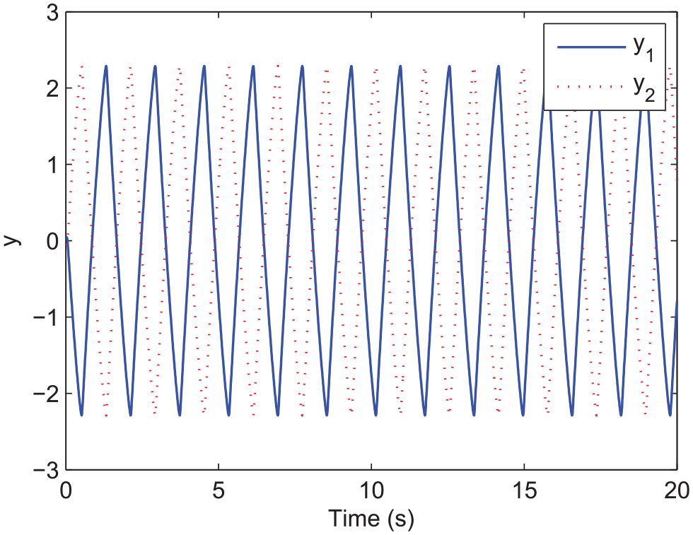
Simulated time histories of two separate Rayleigh oscillators with different initial conditions ((0.05, 0) and (−0.05, 0)).

Simulated time histories of two Rayleigh oscillators with different initial conditions ((0.05, 0) and (−0.05, 0)) coupled with coupling coefficients

Simulated time histories of two Rayleigh oscillators with the same initial conditions ((0.05, 0) and (0.05, 0)) coupled with coupling coefficients
When the damping coefficients of the Rayleigh oscillators are equal to 1, Figures 7 and 8 show the simulated phase planes and time histories of the Rayleigh oscillators with various amplification coefficients and stiffness coefficients listed in Table 2, respectively. Observing Figure 7, the amplifications of the Rayleigh oscillators increase from 1 to 13 with the amplification coefficient

Simulated phase planes of Rayleigh oscillators with amplification coefficient

Simulated time histories of Rayleigh oscillators with stiffness coefficient
Performances of the CPGCC method
Figures 9 and 10 show the simulated time histories of the rotations of TDFR’s two joints (

Simulated time histories of the angles of TDFR’s two joints controlled with the proposed CPGCC method with coupling coefficients

Simulated time histories of the angles of TDFR’s two joints controlled with the proposed CPGCC method with coupling coefficients
Experiment and results
Experimental setup
Figure 11 shows the experimental setup of a TDFR established on a real-time simulation system (myRio, National Instrument). Observing Figure 11, the experimental setup of a TDFR comprises the TDFR, a driver, and a real-time simulation system. The real-time simulation system is used as the controllers via the proposed CPGCC methods, as well as to process the feedback sensing signals. Two joints of the TDFR are driven by two servo motors, respectively. The driver is used to provide the desired driving voltage according to the controlled signals from the controllers.
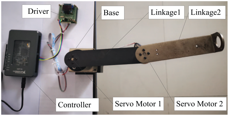
Experimental setup of a TDFR based on the real-time simulation system.
Results
Figure 12 shows the time histories of the angles of TDFR’s two joints controlled by the proposed CPGCC method with coupling coefficients

Experimental time histories of the angles of TDFR’s two joints controlled with the proposed CPGCC method with coupling coefficients

Experimental time histories of the angles of TDFR’s two joints controlled with the proposed CPGCC method with coupling coefficients
Conclusion
To synchronously control TDFR’s two joints, by utilizing two coupled Rayleigh oscillators with the mutual locked phases as the referred models of the two joints, the CPGCC method is proposed. On these bases, the co-simulation model of the proposed CPGCC method is established via ADAMS and MATLAB/Simulink, and the performance of the CPGCC method on synchronizing motions of TDFR’s two joints is numerically simulated. Furthermore, the experimental setup of a TDFR is established based on the real-time simulation system via the proposed CPGCC method. And experiments are carried out on the established experimental setup. The simulated results of the Rayleigh oscillators show that Rayleigh oscillators can be coupled by adding coupling terms, and the phase difference can be changed according to coupling coefficients. The simulated and experimental results of the CPGCC method show that phases of the controlled TDFR’s joints are mutually locked to others, and their motion pattern can be adjusted through the coupling terms in the CPGCC method. In conclusion, the proposed CPGCC method can be used to synchronously control the TDFR’s joints and adjust the rhythmic pattern of the TDFR. Different from the conventional methods which apply the coupled Rayleigh oscillators for generating the reference trajectories and applying additional PD controllers for tracking these trajectories, the coupled Rayleigh oscillators in this article are used as the controllers via their convergences. Therefore, this article illustrates the feasibility of designing the coupling controllers without using the additional tracking controller, which is useful for the multi-joint robot.
Footnotes
Declaration of conflicting interests
The author(s) declared no potential conflicts of interest with respect to the research, authorship, and/or publication of this article.
Funding
The author(s) received no financial support for the research, authorship, and/or publication of this article: This work has been supported by Scientific and Technological Research Program of Chongqing Municipal Education Commission (Project No. KJQN201801328), Scientific and Technological Research Program of Chongqing University of Arts and Sciences (Project No. R2018JD03).