
Abstract
This article first puts forward the shortcomings of current AMT starting control in the preface. Then, in the second chapter, the dynamic analysis of the starting process was carried out, and the three requirements of starting control were clarified: dynamic requirements, smoothness requirements and low slippage requirements; it was clarified that dynamic requirements were the main control objectives of starting control, smoothness Performance requirements and low clutch wear requirements are constraints.
In the third chapter, the optimal control principle of the AMT starting is proposed; the clutch target engagement amount is determined according to the power requirements, the engine speed control strategy and the engine target speed are determined according to the low slip wear requirements, according to the requirements of ride comfort, the clutch engagement speed and synchronous compensation torque are determined, and an optimal starting control method with zero synchronous shock based on torque compensation is proposed. Based on this, the optimal starting controller with three control loops is designed in Chapter 4, it realizes the functions of closed-loop control of driver torque demand, closed-loop control of sliding impact degree, closed-loop control of zero synchronous impact, and closed-loop control of engine speed with low sliding power.
Finally, the vehicle test and simulation verification in Chapter 5 confirms that the control method proposed in this paper can effectively meet the starting control goal and eliminate the synchronization shock simply and efficiently.
Introduction
AMT starting control is the most core key technology in AMT control system. Engineering and academia have put a lot of energy into it for many years. However, there are still many problems in AMT starting control strategy.
First of all, in the selection of controlled objects, the clutch control is usually studied, but the collaborative control of the engine is ignored. This paper considers that the control process of the starting process is a process in which the power torque generated by the engine according to the driver’s throttle opening and the load torque generated by the driver’s clutch depth are coordinated.
Secondly, the output parameter of the control strategy usually uses the engagement speed as the control output parameter; this article considers that the clutch engagement speed only affects the constraint index of the impact of the starting slipping process and is not a critical parameter. The engine speed belongs to the control target rather than the control output parameter. However, the clutch engagement amount and the requested engine torque are the basis of the engine load torque and the starting torque of the entire vehicle.
Thirdly, in terms of starting synchronous impact, more attention is usually paid to the impact degree at the start of the grinding stage, while the impact degree at the synchronous moment is ignored. There are also certain defects in the mechanism and solution of synchronous impact. Synchronous shock is the shock that occurs when the engine speed and the clutch speed are synchronized. During the development of AMT, the synchronous shock has a short action time and is often easily ignored. However, if the control is not good, the impact will be very serious. The synchronous shock is generated during the transition of the clutch transmission torque from sliding friction to static friction. It appears to be due to the difference in angular acceleration between the engine and the clutch before synchronization. The deeper reason is that the engine torque before synchronization Caused by unreasonable clutch torque matching. References1–3 deduced from the dimension of acceleration that the synchronous shock is proportional to the angular acceleration difference between the engine and the clutch before synchronization. It is considered that the method to eliminate synchronous shock is to make the angular acceleration difference between the engine and the clutch close to 0 before synchronization. The conclusion is derived based on the assumption that the engine torque is constant before and after synchronization and has some guiding significance. However, based on this conclusion, the best solution to the synchronization shock has not been found. References4–6 are based on the conclusions derived from references,1–3 and improved derivation. It proposes to take the clutch torque as the controlled object, by changing the clutch engagement amount, the clutch transmission torque, and the engine torque at the synchronization time are both changed to 0, thereby eliminating the synchronization shock. This method does eliminate the synchronous impact, but it adds two impacts during the slip phase and the post-synchronization phase, which is not worth the loss. And in the process of starting, it is a wrong way to reduce the driving torque of the whole vehicle to 0, which seriously violates the driver’s torque demand; references7–10 proposes to reduce the synchronous shock by adjusting the clutch torque adjustment, but the author only uses the clutch to transmit the torque as the controlled object and observes through the shaft. Torque is used for starting control, and zero synchronization shock cannot be achieved.
Dynamic analysis of starting process and starting control requirements
Dynamics of the starting process
As shown in Figure 1, usually we can divide the starting process into three stages: the idle stroke stage, the skid-slip stage, and the post-synchronization stage. Among them, the clutch is in the idle stroke stage (OA stage) before the clutch starts to transmit torque, and the engine speed is synchronized with the clutch speed in the post-synchronization stage (C stage). Between the two is the sliding stage (AC segment).

The starting process of the clutch.
Automobile power transmission system consists of engine, flywheel, clutch friction disc, gearbox, transmission shaft, main reducer, differential, wheels, etc. The focus of this article is to analyze and study the synchronous impact of clutch engagement. Therefore, the power transmission system can be reduced to a two-degree-of-freedom dynamic model, the engine crankshaft and flywheel are equivalent to one degree of freedom, and the clutch friction disc, gearbox, the drive shaft, main reducer, differential, wheels, and vehicle are equivalent to another degree of freedom, while ignoring the effect of damping in the model, and simplifying the dynamic model at start, as shown in Figure 2.
(1) Empty Stroke Phase

(2) Slipping


(3) Post-synchronization


(4) Can be transformed into


In the formula:
Te: Engine torque
TL: Driving resistance torque
Tc: Clutch torque
Je: First degree of freedom moment of inertia
Jc: Second degree of freedom moment of inertia
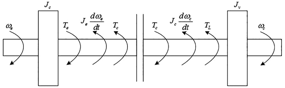
Mechanical model of clutch engagement process.
Control requirements for the start-up process
The starting control is the coordinated control of the engine and the clutch, so that the vehicle can start quickly with the starting torque required by the driver, and meet the constraints of vehicle smoothness and low wear of the clutch. Therefore, the starting control must meet the following three control requirements:
Motivational requirements: It is necessary to fully reflect the starting intention of the driver, that is, to make the vehicle generate the starting torque required by the driver according to the opening degree of the accelerator pedal, so that the driver obtains the corresponding starting feeling; it is the main control target of the starting control.
Ride comfort requirements: It means that the dry clutch can be engaged quickly and smoothly during the starting process without generating large shocks and vibrations that make the driver and passenger feel uncomfortable; it is a constraint requirement for vehicle starting control.
The index that can directly reflect the ride comfort of a vehicle is the impact degree, which is the rate of change of the vehicle’s longitudinal acceleration; its mathematical expression is:

According to car theory, the acceleration of a vehicle is:

In the formula:
i0: Speed ratio of main reducer
ig: Transmission ratio
TW: Air drag torque
Ti : Uphill drag torque
Tf : Rolling resistance torque
δ: Vehicle rotation mass conversion coefficient
Ma: Total car quality (kg)
rr: Tire rolling radius
Because the vehicle speed during the starting process is very low, the wind resistance is basically 0. Because the starting time is very short and the driving distance during the starting process is short, the rolling resistance coefficient and road gradient of the starting process remain basically unchanged, so the wind resistance, slope resistance, and the rate of change of rolling resistance is 0. Therefore, the impact of the starting process can be expressed as:

In the formula:

During the starting process of the vehicle, ξ is determined by the vehicle itself and remains basically unchanged. Therefore, it can be seen from equation (12) that the change rate of the traction torque of the vehicle is the main influencing factor of the impact degree of the vehicle during the starting process, that is, the impact degree of the starting process mainly depends on the change of the transmission torque of the clutch.
3. Low wear clutch requirements: It refers to the friction torque generated by the gradual engagement of the clutch during the starting process, and transmits the power output by the engine to the drive system. The friction torque is generated by the clutch’s master and slave disks. The clutch wear will inevitably occur during the gradual increase of friction torque, which can directly reflect the wear of the clutch is slip wear work. The greater the slip wear work, the greater the wear between the clutch pressure plate and the friction plate, and vice versa. It is an important indicator for measuring the service life of the clutch.
Slip work Lc refers to the magnitude of the energy generated by sliding friction to perform the work in order to eliminate the speed difference between the clutch pressure plate and the friction plate during the engagement process. The greater the slipping work, the greater the wear between the clutch pressure plate and the friction plate, and the smaller the conversely, it is an important indicator to measure the service life of the clutch.
During the starting process of the vehicle, the clutch torque is increasing as the displacement of the release bearing decreases. Taking the clutch half-joint as the dividing point, the slipping work of the starting process of the vehicle can be divided into two stages:
In the first stage, although the friction torque Tc between the clutch master and slave discs is constantly increasing, it is always smaller than the driving resistance torque Tr of the vehicle. At this stage, the vehicle is always at a standstill, and the speed difference between the master and slave discs is
In the second stage, as the clutch pressure plate and the friction plate are further engaged, the vehicle starts to move, and the speed difference between the master and slave plates is
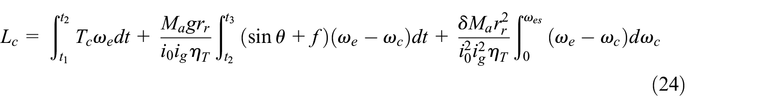
In summary, the mathematical expression of the slip grinding work during the starting process is:

In the formula:
Tc: Clutch torque
ne: Engine speed
nc: Clutch driven disc speed
t1: The moment the clutch master-slave disc comes into contact
t2: When the speed of the clutch driven disk is greater than 0
t3: The timing of the clutch master and slave disc rotation speed synchronization
It can be known from equation (14) that the influencing factors of the starting slip grinding work mainly include the speed difference between the clutch master and slave discs, the starting slip grinding time and the clutch friction torque.
Determination of optimal starting control principle
The starting process should take the driver’s starting intention as the prerequisite for control. The starting power requirement is the main control target of the starting control, while the ride comfort requirement and the clutch low wear requirement are only two icing on the cake control icing on the cake; therefore, we follow the primary-secondary relationship and propose corresponding control methods, which meet the three requirements of the starting control in turn. An optimal AMT starting control strategy is obtained, and the input variables, output variables, and control objectives of the optimal starting control are determined. The starting control factors such as the engine speed control strategy, the engine target speed, the clutch target engagement amount, the clutch engagement speed, and the synchronous compensation torque are determined.
Determine the clutch target engagement amount according to the power requirements
When the vehicle starts, the driver’s intention to control the automatic transmission vehicle is reflected in the throttle opening. The throttle opening reflects the output power of the engine and also reflects the driver’s demand for the engine’s output torque. It is an important influencing factor for determining the clutch engagement amount. Therefore, the throttle opening is used as the system input amount in the starting control; according to the dynamic analysis of the starting process and the requirements of the starting control, it can be seen that the control process of the starting process is actually a process in which the power torque generated by the engine according to the driver’s throttle opening is coordinated with the load torque generated by the driver’s clutch coupling depth. During the entire process, if the load torque is less than the power torque, a higher engine speed and slip work will be generated. If the load torque is greater than the power torque, it will cause a large decrease in the engine speed, which may severely stop the engine. The best starting process is to increase the power torque and the load torque simultaneously, and adjust the increase speed of both to meet the impact requirements. In order to maximize the driver’s starting demand, we use the maximum engine torque at the driver’s required throttle opening as the driver’s required torque at the start, and then determine the target clutch amount.
Each throttle opening of the driver corresponds to a maximum torque speed

According to the clutch torque transmission characteristics, we know that the clutch displacement x is proportional to the clutch transmission torque Tc. See equation (16):

In the formula:
Z: Number of friction surfaces
µc: Coefficient of friction
Rc: Average friction radius of driven disc
Kc and cc: constant
To achieve the driver’s torque, it is also necessary to make the clutch transmission torque equal to the maximum engine torque that is:

By combining equations (15) to (17), the target engagement position of the release bearing at the target engine speed corresponding to each accelerator opening can be obtained as:

As can be seen from the above formula, the throttle opening degree corresponds to the clutch engagement amount. During the starting process, the amount of engagement of the clutch needs to be determined by the throttle opening degree so as to meet the driver’s starting torque demand. The corresponding relationship between the two is shown in Figure 3.

Correspondence between clutch engagement and accelerator opening.
Determine engine speed control strategy and target engine speed based on clutch low-slip requirements
Determination of the constant speed control principle of the starting engine
In the current starting control theory, the mainstream engine speed control strategy is the principle of constant speed control. This is a control strategy that is most in line with the starting habits of mature drivers. A lot of research has been done on it in the academic community, but they lack a complete, comprehensive formula derivation lacks the theoretical basis in the broadest sense. Based on an in-depth study of the starting process, this paper takes the minimum friction work as the control target, and uses the integral first median theorem to deduce the principle, providing a solid and effective theoretical basis for the control principle.
From equation (14), the mathematical expression of slip grinding work can be transformed into

Integral first median theorem: if functions f(x) and g(x) are integrabled on a closed interval [a, b], and g(x) is invariant on [a, b], then at least one point ξ exists on the integration interval [a, b] to make the following formula true:

According to the first median theorem of integrals, there must be a ξ to make the slip work:

Graphing equation (21) as shown in Figure 4, it can be found that when the Tc is determined, the sliding work depends mainly on the area S1 of the shadow portion; that is, to reduce the sliding work Lc, the area S1 of the shadow portion must be reduced; the BD segment of the clutch speed line in the figure depends on the clutch torque Tc. After the clutch engagement process is determined, the BD segment curve is determined. In the case where the joint speed point D is determined, S1 can be minimized only by making ne a straight line; as shown in Figure 5, the starting process is to adjust the fuel injection of the engine to balance the power torque output by the engine at a stable speed with the load torque Tc of the clutch, so that the engine speed nec is maintained at a stable speed, the shadow area can be effectively reduced from S1 in Figure 4 to S2 in Figure 5, and the slip work can be effectively reduced. That is, the principle of constant engine speed control can effectively reduce the slip work during the starting process.
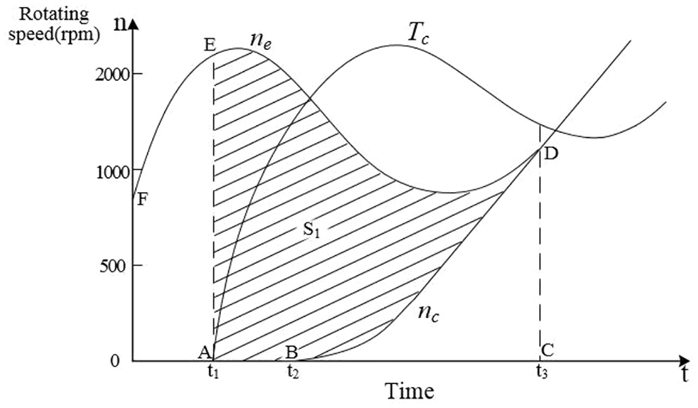
Analysis of slip friction work of clutch at start.
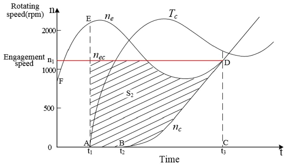
Analysis of constant-speed slip grinding work of the engine during the starting process.
Although the control method in Figure 5 can effectively reduce the slip work, the method obtained is not the smallest slip work. To further reduce the slip work, the engagement speed must be reduced to the engine idle speed, as shown in Figure 6, starting with the idle speed as the target speed, starting at constant engine speed can effectively reduce the shadow area from S2 in Figure 5 to S3 in Figure 6. Since idle speed is already the lowest stable speed of the engine, the engine idle constant speed control is the engine control method with the smallest slip friction during the start.
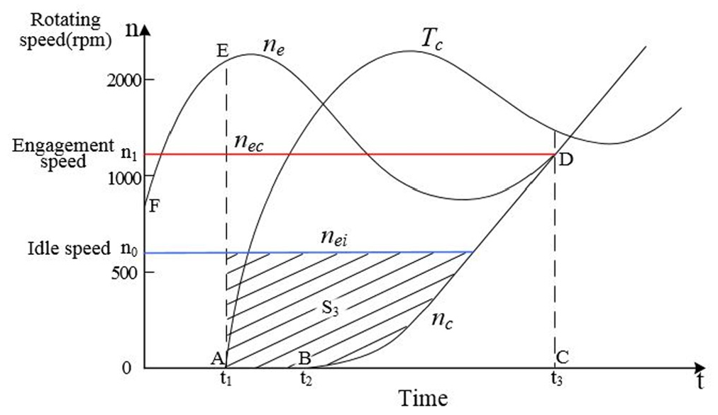
Analysis of engine idling and constant speed slip work during starting process.
Determination of target engine speed
After the principle of constant speed control in the starting process is determined, the target speed of the engine needs to be determined. In this paper, the target speed is derived from a theoretical perspective.
During the starting process, the vehicle speed is very low, so the impact of wind resistance is ignored in this article. According to the theoretical car of the vehicle, the relationship between the acceleration of the vehicle and the angular acceleration of the clutch driven disk is as follows:

It can be deduced from Vehicle dynamic equation and equation (22):

Bringing equation (23) into the formula of slip grinding work equation (14) gives:
where:
In the case of neglecting the starting resistance,11 θ = 0, t2 = t1, we get:
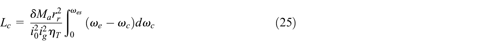
The starting process uses constant speed control, that is ωes = ωe then

It can be known from equation (26) that when the starting resistance is not considered, the slip grinding work of the engine at a constant speed depends on the engine speed. In order to minimize the starting slipping power, the starting engine speed must be controlled to the minimum, and the minimum stable engine speed is the engine idle speed. Therefore, by adjusting the combination of the amount of injection of the engine oil and the clutch during the starting process, the engine speed is maintained near the idle speed, which is an important means to reduce slip work.
If the minimum slip work is the control target, the idle speed is the target speed of constant speed control, but the driver’s demand for the starting torque should also be considered during the starting process, and the driver’s demand should be the highest priority. The throttle opening degree reflects the driver’s torque demand for the engine after comprehensive consideration of all aspects of the driver. Therefore, in addition to minimizing the slip work, the maximum torque of the engine must be used. In addition, through Figure 7, it can be seen that when the engine’s throttle opening is below 60%, the idle torque is the largest, and the slipping work at this speed is the smallest. The idling speed should be the starting target speed. When the engine’s throttle opening is above 60%, the maximum torque point moves up. The priority of power should be higher, so the slip work should be sacrificed to ensure the power, and the maximum torque speed is the target speed. In summary, this paper selects the speed point with the maximum torque at different throttle openings of the engine as the target speed of the engine under constant speed control. At start, the target speed for constant engine speed control at different accelerator openings is shown in Figure 8.
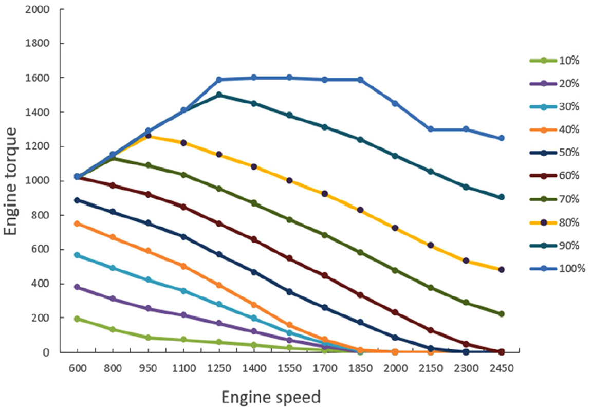
An engine external characteristic curve and partial load characteristic curve.

Correspondence between target engine speed and throttle opening.
In summary, the control strategy of constant speed control with the speed of the maximum torque moment point under different throttle openings as the target speed in the starting control has the following advantages:
Can effectively meet the driver’s starting needs.
It can effectively reduce slipping work during starting and reduce clutch wear.
From equation (26), it can be known that the lower the engine speed, the smaller the starting slip-grinding work.
In practical applications, the engine speed may be higher or lower than the target speed. Usually, the high and low engine speeds are balanced by increasing the clutch engagement amount or increasing the engine fuel injection amount.
Determine clutch engagement speed and synchronous compensation torque according to ride comfort requirements
The starting shock is composed of two kinds of shocks: slipping shock and synchronous shock. The slipping shock is the shock generated during the slipping stage and the shock caused by the change in clutch friction. Synchronous shock is the shock generated at the synchronous moment, which is the shock caused by the transition of clutch transmission torque from sliding friction to static friction.
Determine clutch engagement speed based on slipping shock
The expression of the clutch transmission torque in the slipping stage can be found in equation (16), substituting equation (16) into equation (12), the degree of impact can be expressed as:

The relationship between the pressing force between the clutch master and slave disks and the clutch release bearing stroke can be linearly expressed as:

In the formula: kc and cc are constants.
By applying equation (28) to equation (27), we can get the expression of impact degree:

In summary, during the start of the vehicle, before the clutch half-engagement point, the speed of the clutch driven disk is 0, the vehicle is stationary, and there is no impact; After the clutch half-engagement point, the speed of the clutch driven disk is greater than 0, and the engagement speed of the clutch is the only influencing factor and controllable variable of the shock degree, and the relationship between them is proportional. Therefore, to achieve a smooth start of the vehicle, the engagement speed of the clutch must be controlled within a reasonable range.
According to equation (29), it can be known that the vehicle’s impact depends on the clutch engagement speed vc, and the mathematical expression of the clutch engagement speed can be obtained:

There are two quantities to be determined in equation (30):

Determine synchronous compensation torque based on synchronous impact
Analysis of the mechanism of starting synchronous shock
According to equation (12), it can be seen that the magnitude of impact is mainly affected by the rate of change of friction torque, that is, the degree of impact is directly proportional to the rate of change of clutch torque.
Synchronous shock is mainly caused by the change in clutch transmission torque before and after synchronization. The speed difference between the clutch and the driven disk before synchronization is not 0. The clutch transmission torque is the sliding dynamic friction torque, and its size depends on the positive pressure of the clutched and driven disk.

After synchronization, the speed difference between the clutch and the driven plate is 0, and the clutch torque is the static friction torque. The clutch torque depends on the engine torque.

The dominant conditions of the two have undergone a qualitative change. If the synchronization time cannot be excessively exceeded, it will inevitably have an impact, so we must control the synchronization time so that there is no excessive impact at the synchronization time. In order to better analyze the problem, we will add a control process to the starting process at the synchronization time.
In Figure 1, we let time tc1 be the time before synchronization, time tc2 be the time after synchronization, and time tc1: the clutch master-slave disc rotation speed is not synchronized, which belongs to the slipping state. According to the dynamic equation:


Time tc2: The speed of the clutch master–slave disc is synchronized, which belongs to the synchronous state. According to the dynamic equation, we can get:


With the engine torque unchanged before and after synchronization, equation (36) minus equation (39) gives:

According to equation (40):

According to equation (34):

Substituting equation (41) into equation (37) gives:

From equation (43) minus equation (42), the impact degree at the synchronized moment is:

According to equation (44), under the condition that the engine torque before and after synchronization is unchanged, if the angular acceleration of the engine and the clutch before synchronization is different, synchronous shock will occur.
Zero-synchronous impact control method based on torque compensation
Synchronous shock occurs because the clutch transmission torque is unreasonably matched with the engine torque and load torque during the process of excessive friction from the friction to the synchronization phase, which results in the change in clutch transmission torque. The transmission torque of the clutch is proportional to the clutch position during the friction. As long as the clutch position is guaranteed, zero shock can be achieved; in the synchronization phase, to achieve zero synchronous impact, the angular acceleration of the driven disk must be the same before and after synchronization, that is,


Subtracting equation (46) from equation (48) gives:

According to equation (49), when the angular acceleration of the clutch and the engine are different, we can eliminate the synchronization shock by increasing the engine torque at the synchronization time. With this method, synchronization is not required to adjust the angular acceleration difference between the engine and the clutch to 0 at the synchronization time, and only the engine torque needs to be adjusted at the synchronization time. There is no complicated linkage effect on the control, and it is simple and effective; and it is not necessary to change the clutch transmission torque, which can ensure the power and smoothness of the vehicle.
Optimal starting controller
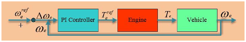
According to the starting control principle introduced earlier, we designed the optimal starting controller. As shown in Figure 9, the entire control architecture is divided into three control loops: power performance ring, ride comfort ring and low wear clutch ring. The controller uses the throttle opening as the only input variable, and through three control loops, the driver’s torque demand closed-loop control, slip friction closed-loop control, zero-synchronous impact closed-loop control, and low-slip are implemented. The three control loops are described below.
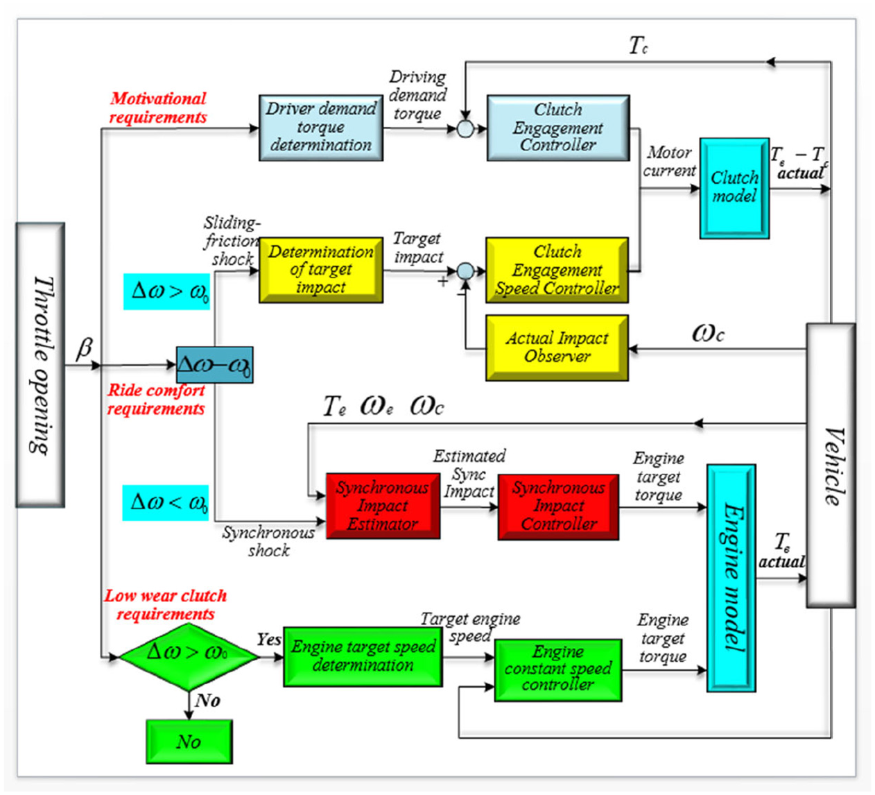
Optimal starting controller design architecture.
Power performance ring
The control loop first calculates the maximum engine torque at the throttle opening based on the throttle opening, and uses this as the driver’s required torque, which is input to the clutch engagement amount controller and is calculated by the formula.

Calculate the duty cycle of the motor, and at the same time, the controller will correct the motor current i1 according to the deviation of the driver’s required torque and the actual torque of the clutch.
Ride comfort Ring
According to the previous analysis, the starting impact can be divided into two types: sliding impact and synchronous impact. The control loop is divided into two control loops, the sliding impact control loop and the synchronous impact control loop.
(1) When the speed difference
First, calculate the target impact based on the throttle opening. When the impact is less than the maximum impact limit, the target impact is divided into three levels according to the throttle opening β. The impact is j1, j2, j3, and when β ≤ 30%, the impact degree is j1, when 30% < β < 70%, the target impact degree is j2; when β ≥ 70%, the target impact degree is j3; after the target impact degree is input to the clutch combined with the speed controller, the controller will use the actual formula.

The clutch target engagement speed is calculated, and the motor current limit
(2) When the speed difference
First, the synchronous shock estimator will estimate the estimated value of the synchronous shock in the current state based on the actual engine torque, engine angular acceleration, and clutch angular acceleration.

Then the zero-synchronous shock controller will target zero-synchronous shock, and calculate the target engine torque based on the estimated value of the synchronous shock, the actual engine torque, the angular acceleration of the engine, and the angular acceleration of the clutch.

And output to the engine model, the actual engine torque is output to the vehicle model through the engine model.
Low wear clutch ring
As shown in Figure 10, when the difference between the speed of the engine and the clutch
Engine constant speed controller.
Vehicle test and simulation verification
This paper validates the optimal starting control method of zero-synchronous shock AMT based on torque compensation through vehicle tests and simulation.
Vehicle test verification-starting curve at different throttle openings
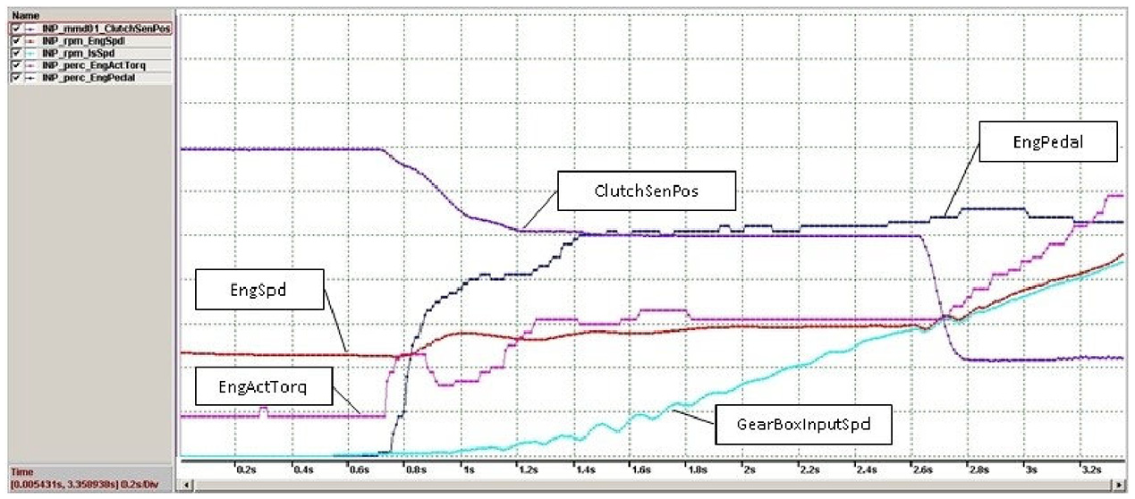
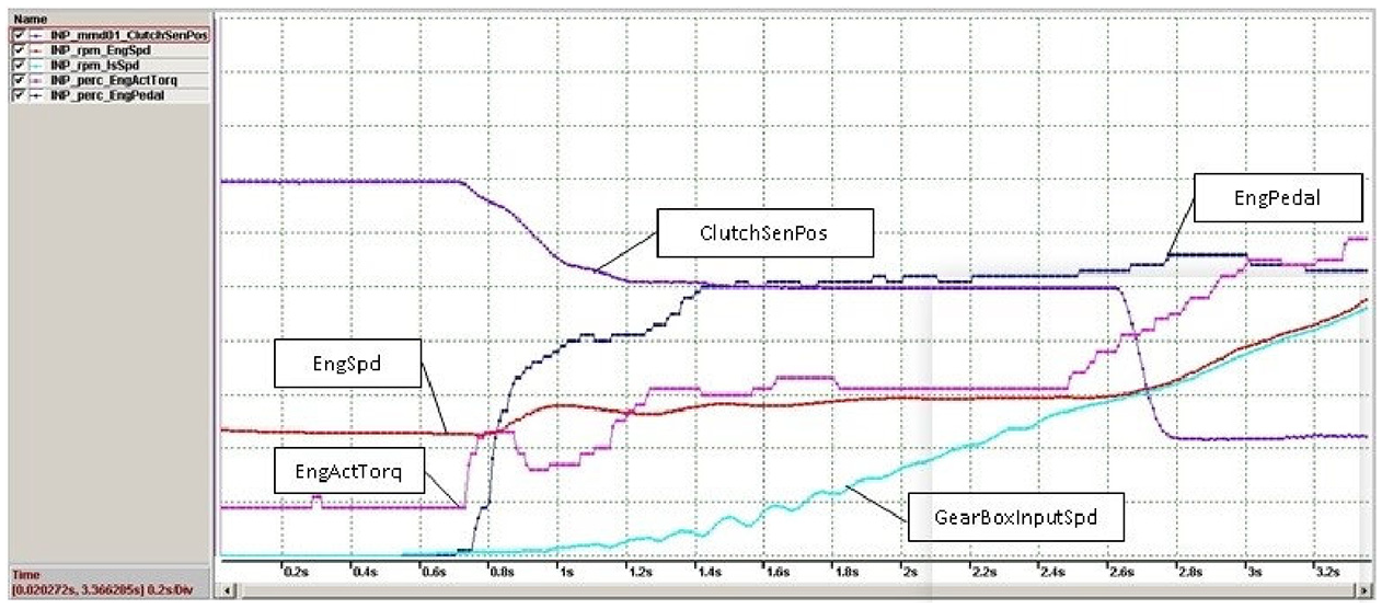
As shown in Figures 11 to 18, it can be seen that the starting curve of different accelerator openings is that the starting control system satisfactorily meets the driver’s starting dynamics needs through the precise coordination of the clutch position. Through reasonable engine constant speed control, the starting slip grinding work is controlled within the minimum range, through the control of the clutch coupling speed, the slip impact is controlled within the required range.
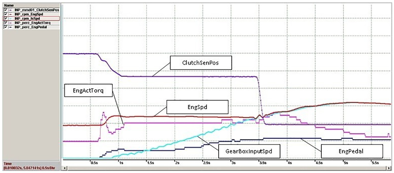
5%–10% throttle opening data (uncontrolled torque).
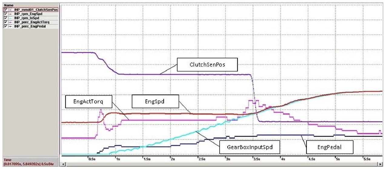
5%–10% throttle opening data (torque control).
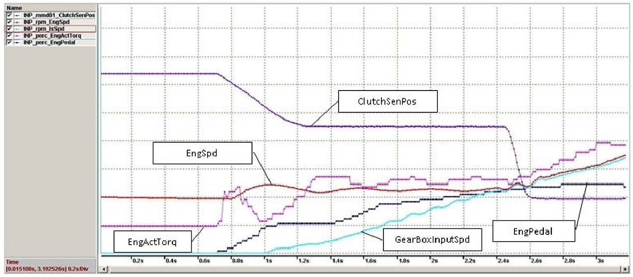
20% throttle opening data (uncontrolled torque).

20% throttle opening data (torque control).

30% throttle opening data (uncontrolled torque).

30% throttle opening data (torque control).
50% throttle opening data (uncontrolled torque).
50% throttle opening data (torque control).
Comparative simulation verification of zero synchronization impact
As shown in Figures 19 and 20, it can be seen from the comparison chart that before the synchronous torque compensation control of the engine torque, the input shaft speed generated a shock at the synchronization time, and the vehicle produced a synchronous shock; after the synchronous torque compensation control of the engine torque, the input shaft speed did not vibration is generated, and the vehicle does not generate a synchronous impact. By performing synchronous torque compensation control on the engine torque, the synchronous shock can be quickly and effectively eliminated.

Shock before control.

Shock elimination after control.
Conclusion
In this paper, the insufficiency of the current starting control strategy is studied in depth, especially the in-depth analysis of the research status of the starting synchronous shock generation mechanism and the solution method; then the dynamic analysis of the starting process is carried out, and the three aspects of the starting control are clarified big demand.
According to the starting control requirements, the control principle of optimal starting control is proposed: (1) According to the dynamic requirements, the clutch engagement amount is determined based on the dynamic characteristics of the starting process and the clutch torque transmission characteristics; (2) According to the requirements of low slip grinding, with the minimum slip work as the goal, the first median theorem of integral is used to theoretically derive the starting speed control principle of the engine at constant speed. And taking into account factors such as the driver’s starting demand, engine characteristics, and slip work, the target engine speed of the constant-speed starting principle was determined; (3) Determine the clutch engagement speed according to the ride comfort requirements; (4) Based on the proportional relationship between the impact degree and the change in torque, the deep-seated causes of the synchronous impact are analyzed, and the innovative method of torque compensation is used to achieve zero synchronous impact. An optimal starting control method based on torque-compensated zero-synchronous shock is proposed; based on this, an optimal starting controller with three control loops is designed to realize driver’s torque demand closed-loop control, slip-impact closed-loop control, zero-synchronous impact closed-loop control, and low-slip grinding engine speed closed-loop control and other functions.
Finally, the effectiveness of the optimal starting control method of zero-synchronous shock based on torque compensation proposed in the paper is verified by vehicle tests, which solves the key problems of engineering and academia’s starting control in AMT for a long time.
Footnotes
Declaration of conflicting interests
The author(s) declared no potential conflicts of interest with respect to the research, authorship, and/or publication of this article.
Funding
The author(s) received no financial support for the research, authorship, and/or publication of this article.