
Abstract
It is important to study the effects of heat flux on the thermo-hydraulic characteristics in a solar cavity receiver because of the non-uniform radiation flux temporally and spatially. In this article, we presented a mathematical model of thermo-hydraulic characteristics of a solar cavity receiver, considering the effect of heat flux distribution on the energy transfer (radiation–conduction–convection). Using the model, the thermo-hydraulic characteristics under high concentrated heat flux were studied and then optimized the characteristics from two aspects: tube diameter (22, 27, 32, and 38 mm) and connection structure of the heating surface (H-type, central inlet/outlet, and vertical U-type). It was found that flow distribution changed smoothly at the diameter of 27 mm with the increase of the heat flux; when the diameter of tubes at the certain distance (1.6σHF) from the spot center was replaced by 38 mm, the thermo-hydraulic characteristics were improved. For the evaporating surfaces, the thermo-hydraulic characteristics of working fluid (water) with the central inlet/outlet connection structure were better than those of the H-type connection structure. For the surperheated surfaces, the vertical U-type connection structure was applied to obtain the high temperature steam. These research findings are helpful for the safe and stable operation of the whole solar power system.
Introduction
A solar cavity receiver is an essential apparatus to achieve solar-thermal conversion in a solar thermal power tower station. Its basic structure is shown in Figure 1. In the solar cavity receiver, several evaporating heating surfaces and superheating surfaces that consist of single parallel panel or multiple parallel panels are arranged in the solar cavity receiver. Evaporating heating surfaces are applied to make working fluid (water) saturated, and the saturated steam is turned into superheated steam to achieve the requirements of steam turbine generation by flowing through superheating surfaces. To improve the solar-thermal conversion, a membrane panel that is made up of several thin-walled tubes is parallel welded together and connected with a horizontal larger diameter manifold is applied on the heating surfaces.1,2 This panel is a basic component of the cavity receiver. Its constituent parallel tubes are called risers, which are connected to a larger diameter manifold placed horizontally. The radiation heat flux in the cavity receiver is always non-uniform temporally and spatially due to one-target focus type of the heliostat field and astronomical feature of sunlight. The structure of the parallel panel and the non-uniform heat flux distribution may lead to the instability of thermo-hydraulic characteristics of phase-change heat transfer fluid in the solar cavity receiver.

Basic structure of a cavity receiver.
Nowadays, most literature is focused on the thermo-hydraulic characteristics caused by the instability of the temporal changing heat flux. There is not a significant amount of literature on the thermo-hydraulic characteristics under the spatially changing heat flux.3,4 It is described in Wang 5 that the research methodology on the hydrodynamic characteristics of a solar receiver mainly included a numerical model, fluid software, and experimental data. In the following, we review references that study the solar receiver.
To understand the influence of receiver design parameters, such as the ratio of riser diameter to manifold diameter, the number of risers, and the length of the risers, on the flow distribution among the solar receiver absorber tubes, Jones and Lior 6 developed a discrete hydrodynamic model without considering the thermal effects. Weitbrecht et al. 7 investigated experimentally the isothermal flow distribution without buoyancy effects and with laminar flow conditions in flat-plate solar collectors by laser Doppler velocimetry measurements. Badar et al. 8 first conducted a computational fluid dynamics (CFD) analysis to find the pressure losses for dividing and combining fluid flow through a tee junction of a solar collector manifold. Then, a theoretical model based on successive approximations was employed to estimate the isothermal and non-isothermal flow distributions in laminar range through a receiver. The receiver consisted of 60 vacuum tubes connected in parallel in reverse (U-configuration) and parallel (Z-configuration) flow arrangements. The results are in reasonable agreement with the available experimental results for U-configuration. 9
Fan et al. 10 theoretically and experimentally investigated the flow and temperature distribution in a solar collector panel with an absorber consisting of horizontally inclined fins. They found by comparing CFD simulations and thermal measurements that there is a good degree of similarity between the measured and calculated fluid temperatures for high flow rates. Boerema et al. 11 investigated the effect of several engineering concepts on the resultant surface temperatures of four tubular billboard receivers, which are designed with single diameter tubes, ideal flow, various diameter tubes, or tube panels in series. Villar et al. 12 developed a transient three-dimensional (3D) mathematical model for solar flat-plate collectors. The model is based on setting mass and energy balances on finite volumes and is used to study the temperature distribution of tube wall and working fluid under uniform or non-uniform flow. Facão 13 designed and optimized header manifold geometry for plate solar collectors. The flow in this optimized geometry is simulated in 3D using the CFD software to confirm the results of the correlation-based model.
Wei et al.14,15 developed a CFD-based evolutionary algorithm to optimize the topology of an inserted perforated baffle, for the realization of target flow distribution among parallel channels. They further applied the evolutionary algorithm to determine the optimal fluid distribution in a tubular pressurized-air solar receiver for the minimization of its peak temperature. Bie et al. 16 developed a discrete mathematical model by changing the inner resistance arrangement based on momentum balance equations and then obtained general formulas of resistance arrangement. Subsequently, verification tests were performed on solar collector arrays by placing relevant resistance components at certain positions corresponding to the calculated results.
Gao et al. 17 used the Badaling 1-MW solar power tower plant for study. They developed a hydrodynamic simulation model based on the working principle of the superheating cavity receiver and obtained the change law of working medium mass flow in different heating surfaces with solar radiation. Based on the heat flux distribution characteristics and the radiative–convective heat exchange in the solar cavity, a non-linear model was constructed to simulate the hydrodynamic characteristics under the natural circulation and then optimized the hydrodynamic characteristics from focus mode and system pressure. 18
As mentioned above, although it is crucial to understand the thermo-hydraulic characteristics of a solar cavity receiver for improving its thermal performance and operation safety, there is only a limited amount of available research that focused on the thermo-hydraulic characteristics of heat transfer fluid of water under high concentrated heat flux. In this article, we make the following contributions:
Unlike the existing references, the heat transfer in the process of radiation–conduction–convection is combined with the heat flux distribution, and a mathematical model of the thermo-hydraulic characteristics of heat transfer fluid of water is developed.
The proposed model is validated by experimental data, and it is shown that the simulation results obtained using the model agree closely with experimental results.
Based on the concentrated heat flux distribution on the receiver, the thermo-hydraulic characteristics are studied using the developed model.
The thermo-hydraulic characteristics of a solar cavity receiver are optimized from two aspects, tube diameter and connection structure of the heat panel. The optimization can be useful in the design, operation, and parameter optimization of the solar power tower system.
Modeling
In the process of absorbing the solar energy, the flow pattern of working fluid (water) phase change in the subcooled status and flowing into the heating surface is shown in Figure 2. The water flows through the partial subcooled boiling zone, subcooled boiling zone, fully developed subcooled boiling zone, and net steam generation zone successively and then turns into the saturation boiling zone finally. It is found in the above-mentioned literature that the maximum and highly varying heat flux appears on the middle and lower section of the parallel tubes, which makes the subcooled boiling zone and net steam generation zone relatively shorter. Therefore, to simplify the modeling and calculation, the heating tube is divided into two areas: single-phase area and water/steam two-phase area.

Flow pattern variation of the working liquid (water) in the vertical tubes with the increase of heat flux.
Under a forced flow, the heated working fluid (water) is taken away rapidly, and then, the physical property parameters of the working fluid (water), such as temperature and density, vary slightly along the radial direction of the tube. Affected by the non-uniform heat flux distribution, the variations of physical property parameters are considered along the axial direction.
In this article, the z-axis of the coordinate is along the flow direction of the working fluid (water) and the x-axis is along the width of panels, as seen in Figure 2. Then, a single tube of the heating surfaces is chosen randomly and divided into several cells. An arbitrary cell on the tube with height dz is chosen and analyzed. The cell is shown in Figure 3. The conservation equations can then be obtained as follows


where

Cell in a single tube used for analysis.
The following equation can be deduced from equations (1)–(3)

For single-phase flow (water or steam), the specific enthalpy increase of working fluid is obtained by equation (5)

For steam–water two-phase flow, the enthalpy increase is related to the vapor quality (xd) of working fluid (water) 19 and can be obtained by equation (6) as follows

where
Subsequently, equation (4) under the condition of single-phase and steam–water two-phase flow can be expressed as follows


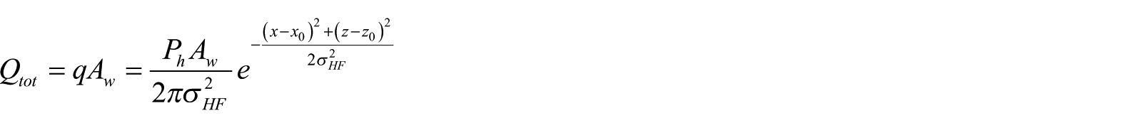
On the basis of energy conservation, the forced convection of water Qabs can be obtained using equation (9) as follows, where the total heat energy Qtot 20 is given

where
A coupling model of the heat transfer calculation and the thermo-hydraulic characteristics under non-uniform heat flux distribution can be constructed for different flow patterns. Then, the model can be solved by writing programs. Finally, the flow distribution and thermal deviation in the parallel tubes with varying heat flux distribution of the solar cavity receiver can be analyzed and obtained:
1. The coupling model for a single-phase (water or steam) flow is given as follows

2. The coupling model for a steam–water two-phase flow is given as

In addition, two parameters, such as thermal deviation and non-uniform coefficient of flow, should be explained:
1. Thermal deviation ηh is the ratio of the increasing enthalpy of working fluid (water) in a single tube and the average increasing enthalpy of working fluid (water) in all the parallel tubes. It is determined by the heat flux distribution, heating area, and flow distribution in the receiver

2. The non-uniform coefficient of flow ηl is expressed by the ratio of the mass flow of working fluid (water) in a single tube and the average mass flow of working fluid (water) in all the parallel tubes, which is related to the structure of tubes, heat flux distribution, header effect, and gravity pressure drop

Model validation
To validate the constructed coupling model of thermo-hydraulic characteristics under non-uniform heat flux distribution, we established an experimental loop to discuss the thermo-hydraulic characteristics in the parallel tubes, which represent the evaporation panel of a solar cavity receiver. The loop consists of five parallel vertical stainless steel tubes arrayed to simulate an evaporation panel of the cavity receiver. The water flow and test section of the experimental loop are given in Figures 4 and 5, respectively. Seen in Figure 4, deionized water packed in a water supply tank is transported to a heat exchanger by a vertical multi-stage centrifugal pump, and the bypass valve installed in the pump discharge is used to regulate the flow rate of water entering the test section. After being preheated by backflow fluid from the outlet of the test section in the exchanger, water is pumped into the test section. Then flowing through a lower header and being distributed into five parallel tubes, water is further heated to the boiling state, while variables such as temperature, pressure, and rate are measured separately. After measuring, water in five separate tubes is collected into an upper header. And it sequentially backflows to the water supply tank after flowing through an exchanger and a cooler. To guarantee a relatively constant pressure, a counterbalance valve is set in the outlet of the test section. The cooling water of the cooler is from the tap water tank by use of an additional circulation system, which consisted of a cooling pump, a cooler, a cooling tower, and a cooling water tank.

Working fluid (water) flow in the experimental loop.

Test section of the experimental loop.
The experimental data obtained in Hao et al. 21 are compared with numerical simulation results obtained under different total flow rate, pressure, and heat flux distribution. It can be observed in Figure 6 that most of the relative errors of flow fall between −15% and +15%, which represent the upper and lower bounds of the errors excepting for the results of Tube 1. The reasons are as follows: (1) The flow in each tube is obtained by the mathematical model of thermo-hydraulic characteristics in the article, which is conducted under steady condition. (2) When the evaporation of working fluid (water) increases in the test, two-phase flow of working fluid (water) causes large pulsation of pressure, which leads to the instability of the system and larger error of flow in Tube 1. In other words, the results of Tube 1 are not taken in account. Besides these, the constructed coupling model is accurate for study and optimization of the thermo-hydraulic characteristics of a cavity receiver under concentrated heat flux distribution.

Comparison of experimental and numerical simulation results.
Results and discussion
In this section, the heat flux and thermal-hydraulic characteristics with respect to different tube diameters and connection types for both evaporation heating and superheating surfaces including thermal deviation, flow distribution, vapor quality, wall temperature, flow resistance, and pressure drop are studied.
Heat flux distribution versus the heating surface of solar cavity receiver
In our previous study, it was observed that the non-uniformity of heat flux distribution along the width of the heating surface had great influence on the thermo-hydraulic characteristics of working fluid (water). Therefore, the heat flux distribution along the height direction of the surface is considered uniform in this article to study the more important effects of varying heat flux distribution along the width.
The heat flux distribution on the surface with different effective deviation coefficients is shown in Figure 7. The figure indicates that with the increase of the effective deviation coefficient, the heat flux curve becomes constant gradually, and vice versa, which means that heat flux distribution gets more and more uniform. According to the heat flux distribution, the thermo-hydraulic characteristics optimization of a cavity receiver will be detailed in the following section.

Heat flux distribution along the width of the heating surface under different effective deviation coefficients of thermal radiation.
Effect of tube diameter on the thermo-hydraulic characteristics
Thermo-hydraulic characteristics of the evaporating heating surface
Flow distribution
The non-uniform coefficient of flow, flow resistance, and pressure drop variations versus varying relative widths of the evaporating heating surface and different tube diameters (D) is displayed in Figures 8 and 9. The system pressure is fixed at 5 MPa, the average heat flux is fixed at 90 kW m−2, and the heat flux effective deviation coefficient is 0.125.
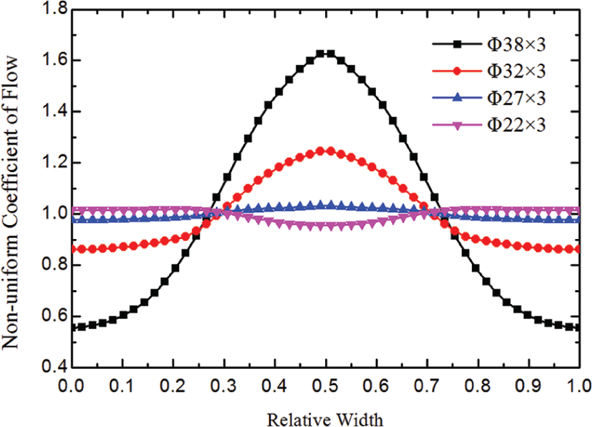
Flow distribution of the evaporating heating surface with different tube diameters (σHF = 0.125).

Variations of flow resistance and pressure drop in the evaporating heating surface with different tube diameters: (a) variation of flow resistance and (b) variation of gravity pressure drop.
It is shown in Figure 8 that when the diameter of the tubes is reduced to 27 mm, the flow distribution becomes steady gradually with the increase of heat flux.
For the same heat flux distribution, with the decrease of tube diameter, the water in the tube flows more quickly and the flow resistance increases with it, as seen in Figure 9(a). When the diameter is 22 mm, the flow resistance plays a dominant role in the overall pressure drop, as seen in Figure 9(b). It can be observed that the positive response characteristics between the flow and the heat flux vanish in the evaporating heating surface. In other words, the flow distribution does not ascend with the increase of heat flux, which should be avoided in the design of the evaporating heating surfaces.
Thermal deviation characteristics
For the same structure of the evaporating heating surface, the thermal deviation characteristics depend on the thermal properties of parallel tubes, that is, heat flux distribution and heating area, and the thermo-hydraulic characteristics of water, that is, flow distribution. The thermal deviation of the evaporating heating surface varies with different tube diameters, as shown in Figure 10.

Thermal deviation characteristics of the evaporating heating surface with different tube diameters (σHF = 0.125).
It is shown in Figure 10 that when the diameter decreases from 38 to 27 mm, the profile of thermal deviation becomes steeper due to the gradual disappearance of the positive response characteristics of flow distribution. However, when the diameter is 22 mm, the thermal deviation is actually less than that with the diameters 32 and 27 mm. The reason is that the heat flux on the surface is reduced due to the decrease in the heating area. The decreased heat flux makes the thermal deviation in the tubes of the concentrated spot center decline slightly, due to which the flow does not ascend with the increase of heat flux when the diameter is 22 mm.
The vapor quality of water for different diameters is given in Figure 11. The heat flux around the concentrated spot center is relatively higher, which gives rise to an increase of outlet steam of water. Otherwise, the evaporation capacity of water in the tubes that are far away from the concentrated spot center region decreases or even becomes zero. The thermal stress of tube material may vary periodically or aperiodically, and as a result, thermal fatigue damage can occur in these tubes. In other words, both the flow and thermal deviation distribution should be considered for choosing an appropriate diameter for the optimization of thermo-hydraulic characteristics of a solar cavity receiver under concentrated heat flux.

Vapor quality of water with different tube diameters.
Thermo-hydraulic characteristics of the evaporating heating surface with different diameter combinations
As seen in Figures 9 and 10, although the positive response characteristics between the flow rate and the heat flux are shown with the diameter of 32 mm, a larger thermal deviation occurs for this value of the diameter. When the diameter increases to 38 mm, the thermo-hydraulic characteristics of the evaporating heating surface are improved, but the increased weight of the evaporating heating surface can cause an increase in cost. This means that a compromise should be reached to study the thermo-hydraulic characteristics of the evaporating heating surface. This compromise is made up of studying the characters with respect to different diameters making up the tubes in the heating surface. In this article, the evaporating heating surface is composed of 50 vertically parallel tubes. The values of diameters are 30, 32, and 38 mm. We consider three different combinations of tubes with different diameters. These combinations are given as 20 (32 mm) + 10 (38 mm) + 20 (32 mm), 15 (32 mm) + 20 (38 mm) + 15 (32 mm), and 10 (32 mm) + 30 (38 mm) + 10 (32 mm). The diameter values are given inside the brackets, and the number outside the bracket shows the total number of tubes having that diameter. These combinations are used to study the flow and thermal deviations of working fluid (water) in the evaporating heating surface, as shown in Figures 12 and 13, respectively.

Flow distribution and heat flux of the evaporating heating surface with the combination of different diameters (σHF = 0.125).

Thermal deviation and heat flux of the evaporating heating surface with the combination of different diameters.
An interesting result is obtained from these two figures. When the number of tubes having the diameter of 38 mm is increased, the thermo-hydraulic characteristics of the evaporating heating surface are better developed. In other words, the positive response characteristics of flow distribution are improved, and thermal deviation is lowered.
Similarly, the outlet vapor quality variations of water in the tubes are reduced, as seen in Figure 14, which reduces the thermal fatigue damage of tubes. However, comparing with the combined parallel tubes of 15 (32 mm) + 20 (38 mm) + 15 (32 mm), when the number of tubes having the diameter of 38 mm increases to 30, the thermo-hydraulic characteristics vary slightly. Hence, for the improvement of thermo-hydraulic characteristics of the evaporating heating surface under concentrated heat flux, tubes that are within the relative width 1.6σHF of the concentrated spot center can be replaced with the diameter of 38 mm.

Vapor quality of the evaporating heating surface with the combination of different diameters.
Thermo-hydraulic characteristics of the superheating surface
Flow distribution
For the superheating surface, the flow distribution is dominantly affected by the flow resistance in the tubes caused by the low density of superheated steam. Hence, the positive response characteristics of the flow are absent. This can be confirmed by the flow distribution of the superheating surface shown in Figure 15, where the system pressure and the heat flux are 5 MPa and 90 kW m−2, respectively.

Flow distribution of the superheating surface with different diameters (σHF = 0.125).
As the diameter of the tubes increases, the heating area increases with it and the heat flux on the surface also increases more sharply. This leads to the decreasing density of working fluid (water). Tube diameter and density of water are attributed to the variation tendency of the flow resistance. Provided the variation of overall pressure drop caused by the increased diameter is larger than that caused by the decreased density, the mass flow of water will be more non-uniform with the increase of diameter. Therefore, we can see from Figure 15 that the non-uniformity of the flow becomes more intense when the diameter increases from 22 to 27 mm. While the diameter gets to 38 mm, the working fluid (water) in those tubes around the concentrated spot center flows quickly due to the combined influence of the increasing diameter and decreasing density, and hence, an increase of the non-uniform coefficient of flow can be seen.
Thermal deviation characteristics
The thermal deviation and wall temperature of the superheating surface with different diameters are shown in Figures 16 and 17, respectively. It is evident in Figure 16 that depending on the heat flux and flow distribution, the thermal deviation of working fluid (water) in the superheating surface becomes more non-uniform with the increase of diameter.

Thermal deviation of the superheating surface with different diameters.

Wall temperature distribution of the superheating surface with different diameters: (a) Φ38 × 3, (b) Φ32 × 3, (c) Φ27 × 3, and (d) Φ22 × 3.
Figure 17 shows the wall temperature at varying height and width coordinates of the superheating surface having different diameters. It can be seen from the temperature bars in the figure that the highest wall temperature decreases with decreasing diameter values. When the diameter is 32 mm, the peak wall temperature on the tubes around the concentrated spot center is 962 K, which already exceeds the allowable temperature of the material (723–923 K). Ablation may take place under this condition, which can greatly threaten the security of the solar cavity receiver.
Effect of connection structure of parallel tubes on the thermo-hydraulic characteristics of evaporating heating and superheating surfaces
Connection structure of parallel tubes
As it is known, the connection structure of parallel tubes is related with the pressure drop between inlet and outlet of a single tube and has a great influence on the thermo-hydraulic characteristics of the overall parallel tubes as well. In this article, with other parameters being constant, three basic structures such as the H-type, central inlet/outlet, and vertical U-type, as shown in Figure 18, in the parallel tubes are chosen to study the effect of connection structure on the thermo-hydraulic characteristics.

Connection structures of parallel tubes: (a) H-type, (b) central inlet/outlet, and (c) vertical U-type.
Thermo-hydraulic characteristics of the evaporating heating surface
Under low mass flow and vapor quality, the phenomenon of vapor and water separation appears due to the dual effects of centrifugal force and gravity of working fluid of water in the elbow of the vertical U-type tube. The heat transfer deterioration may occur at the inside of the elbow, which brings about the rising of wall temperature. The vertical U-type tubes should not be applied in the evaporating heating surface. Hence, the thermo-hydraulic characteristics of the evaporating heating surface with the other two connection structures, that is, the central inlet/outlet and H-type, are studied in this article. For the superheating surface, the thermo-hydraulic characteristics with all the three connection structures are studied.
Flow distribution
The influence of connection structures on the flow non-uniformity under average heat flux values of 90 and 250 kW m−2 is displayed in Figure 19.
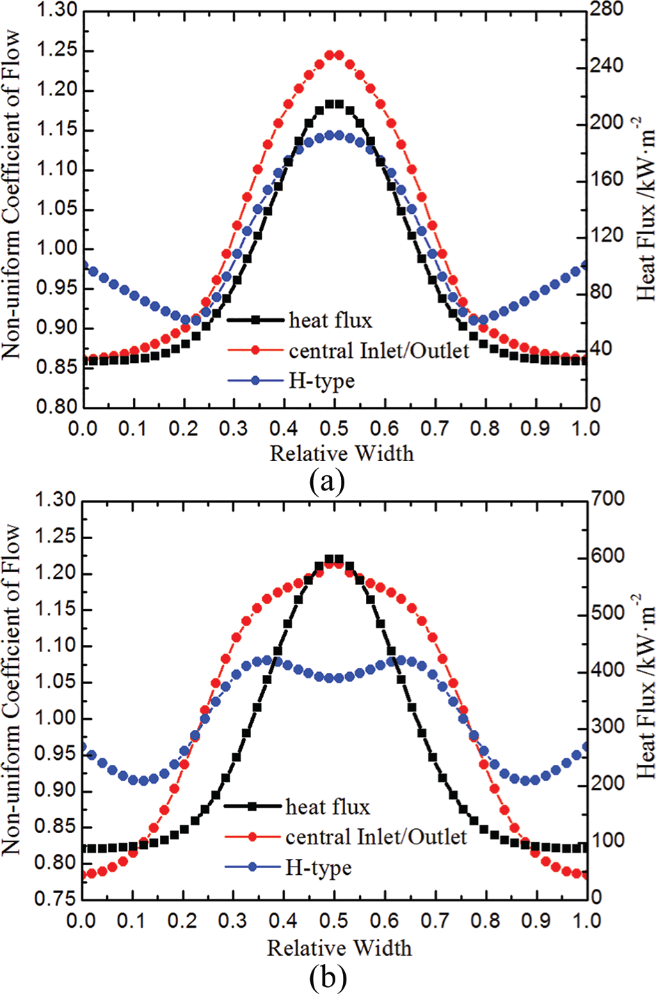
Flow distribution of the evaporating heating surface with different connection structures: (a) the average heat flux is 90 kW m−2 and (b) the average heat flux is 250 kW m−2.
In Figure 19(a), when the average heat flux is 90 kW m−2, the flow distribution has an overall positive response, except in those tubes that are far away from the concentrated spot center. In Figure 19(b), when the average heat flux increases to 250 kW m−2, the flow response characteristics of the evaporating heating surface with the central inlet/outlet connection structure are relatively steady, but the characteristics with the H-type connection structure stay degraded around the concentrated spot center. It is concluded that the response characteristics of the central inlet/outlet connection structure are superior to those of the H-type connection structure.
Thermal deviation and vapor quality characteristics
It can be seen in Figure 20(a) and (b) that the thermal deviation and vapor quality variation of H-type connection structure is relatively larger than that of central inlet/outlet connection structure, when the tubes are near the concentrated spot center. This is due to the positive response characteristics of flow in the evaporating heating surface. However, the opposite is true for tubes that are far away from the concentrated spot center. This is due to the increase of flow. Overall, the central inlet/outlet connection structure shows some advantage over the H-type connection structure in the thermal deviation and vapor quality variation.

Thermal deviation and outlet vapor quality of the evaporating heating surface with different connection structures: (a) the average heat flux is 90 kW m−2 and (b) the average heat flux is 250 kW m−2.
Thermo-hydraulic characteristics of the superheating surface
Flow distribution
As mentioned above, the flow distribution of the superheating surface is directly related to the flow resistance and header effect. The varied trend of mass flow in the tubes is given by Figure 21 with a pressure of 5 MPa and average heat flux of 90 kW m−2. It is seen in Figure 21 that the distribution of the central inlet/outlet connection structure is like that of the H-type connection structure caused by different header effect. However, the mass flow distribution of the vertical U-type connection structure is more non-uniform and presents an asymmetrical distribution, which is due to the features of the vertical U-type connection structure. The tube lengths in the vertical U-type connection structure are different from each other, which leads to asymmetrical distribution of mass flow. Furthermore, as the tubes of the vertical U-type connection structure include ascending and descending branches, the non-uniformity of mass flow is further intensified by counteraction of gravity in the descending branch.
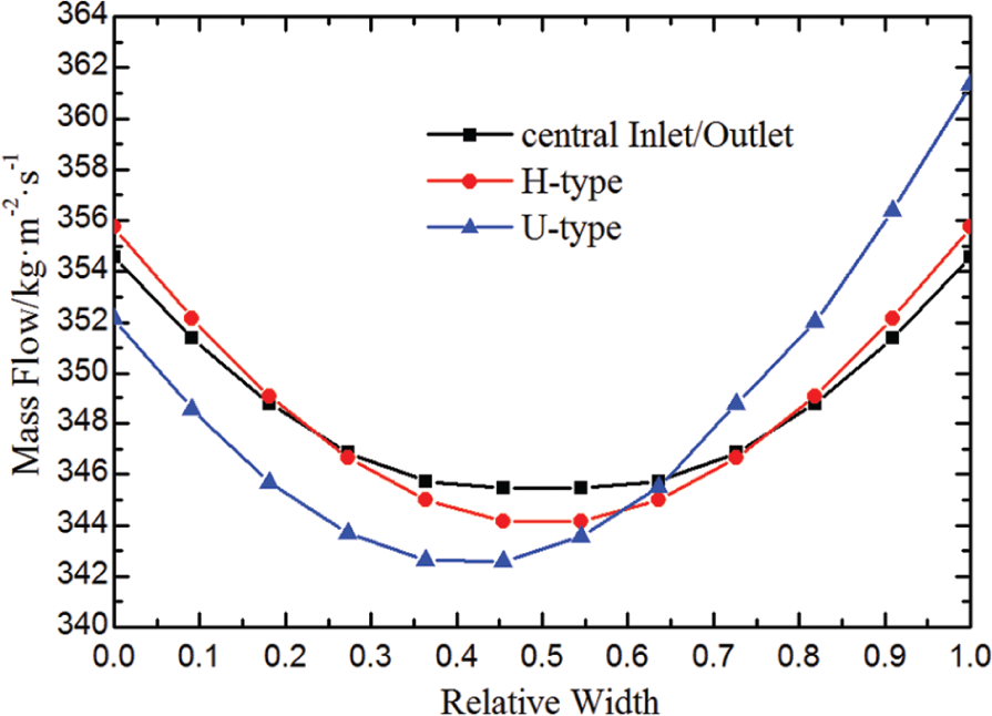
Flow distribution of the superheating surface with different connection structures.
Thermal deviation characteristics
The thermal deviation of the superheating surface with different connection structures is shown in Figure 22. The thermal deviation of the vertical U-type connection structure is asymmetric and lower than that of other connection structures. The thermal deviations of the central inlet/outlet connection structure and the H-type connection structure are similar to each other.

Thermal deviation of the superheating surface with different connection structures.
Conclusion
In this article, a mathematical model of the thermo-hydraulic characteristics is developed based on the energy transfer in the process of radiation–conduction–convection and combined with the heat flux distribution model. The model is first validated by comparing with experimental results. Using the mathematical model, the thermo-hydraulic characteristics are studied under high concentrated heat flux. Subsequently, optimization of the thermo-hydraulic characteristics is carried out with respect to two aspects: tube diameter and connection structure of the heating surface. The optimization can provide guidelines for the design and operation of solar power tower system:
By optimizing the thermo-hydraulic characteristics under concentrated heat flux distribution, the critical diameter of tubes in the heated panel is proposed to be 27 mm. When the diameter of the tubes is 27 mm, the positive response characteristics between the flow and the heat flux vanished in the evaporation heating surface. In other words, the flow distribution did not increase with the increase of the heat flux, which should be avoided in the design of the heating surface. Different diameters of the tube, either 38 or 32 mm, are combined with each other to study the thermo-hydraulic characteristics of the combined parallel tubes. With an increase of the number of tubes having the diameter of 38 mm, the positive response characteristics of the flow in the evaporation surface was improved and the thermal deviation decreased under the concentrated heat flux distribution. When the diameter was 22 mm in the superheating surface, the flow, the enthalpy increment, and the wall temperature are relatively lower under the intensive heat flux. The thermo-hydraulic characteristics are also improved in the superheating surface.
For the improvement of thermo-hydraulic characteristics of the evaporating heating surface under concentrated heat flux, flow distribution and thermal deviation with different diameter combinations is also studied. It concludes that tubes within the relative width 1.6σHF of the concentrated spot center can be replaced by the diameter of 38 mm.
Aiming at three connection structure types of the heating surface, such as the H-type, central inlet/outlet, and vertical U-type, the thermo-hydraulic characteristics under the concentrated heat flux distribution are studied. For the evaporating surfaces, the thermo-hydraulic characteristics of working fluid (water) with the central inlet/outlet connection structure are better than those of H-type connection structure. For the surperheating surfaces, the vertical U-type connection structure is applied to obtain the high-temperature steam practically.
Footnotes
Appendix 1
Declaration of conflicting interest
The author(s) declared no potential conflicts of interest with respect to the research, authorship, and/or publication of this article.
Funding
The author(s) disclosed receipt of the following financial support for the research, authorship, and/or publication of this article: This work was financed by the National Natural Science Foundation of China (grant no. 51961135102).