
Abstract
Several rivers and streams are available in Africa and Asian regions with great potentials not applicable for constructing large hydropower dams but feasible for small and mini hydro generation. This study strive for investigating the impact of splitter blade on pump as turbine performance considering different speed and flow rates. Two specific centrifugal pump models one with six blades without splitter and another with four blades and four splitters were used for the study. The inlet diameter and outlet diameters of both impellers were 104 mm/116 mm, and 160 mm respectively at a designed flow rate Q = 12.5 m3/h, head H = 16 m, rotational speed n = 1450 rpm and efficiency of 56%, outlet impeller width of 0.006 m, a blade outlet angle of 30° was used for the study. CFD simulations were conducted with the use of k-ε turbulence model. The influence of splitter blade position on the performance of pump as turbine in the selected specific pumps with and without splitter blades has been investigated both experimentally and numerically at three different flow rates and rotational speed. The simulated data were in good agreement with the experimental results, the maximum deviation error between the CFD and test for each model are 5.6%, 2.6%, for the head and efficiency; 7.5% and 3.6% at different flow conditions.
Introduction
Energy in recent times has become a very essential commodity which plays a very vital role in human life and the development of every country. Nevertheless its generation may have diverse effect on the environment such as emission of CO2 and other harmful substances to pollute the ecosystem. Hence the need for a hydro renewable energy. A lot of existing energy engineers were not paying attention to these accepted penstock by way of water streams that are capable of operating small and mini hydroelectric power plants. Energy production from small and mini hydropower plants such as pump as turbine is a valid trade-off between capital cost and performances. It has several merits than the custom-made turbines. Pumps are comparatively simple machines with easy maintenance and could be easily found in several developing countries. Pumped storage power plants have the potential to can stabilize electrical power system when the electronic product is excess. Using pump to operate as hydraulic turbine in provides another possibility for energy production particularly mini, micro, and small hydropower. A study was carried out to investigate the best way to set up pump as turbine station for energy generation both numerically and experimentally. 1 Morabito et al., 2 conducted a study on the technical indication of design and the results of a Pumped Hydro Energy Storage (PHES) micro capability. The said micro-PHES was combined in a smart grid with a designed for keeping energy generated to store energy produced by the connected renewable energy sources. Interestingly, this micro-PHES runs with a single centrifugal pump for both pumping and generating phases. It was observe that the pump operated continuously at an all-out efficiency due to the regulated Adjustable speed. An efficiency of 0.71% was recorded out of a variety of 40–120% of the actual design load. It was concluded that an efficiency of 42% was obtained for round-trip energy as adjustable speed was controlled. de Oliveira e Silva et al. 3 conducted a study on PHES system focusing on the installation set-ups. The study revealed that economies of scale are absent in smaller installations which boil down big installation of PHES. Several researchers have conducted various studies both experimentally numerically and theoretically on renewable energy mechanisms development.4–11 Numerical study on the effect of impeller backward blades using centrifugal pump model was carried out by Farid Ayad Hassan et al., 12 under different flow conditions. The blades were altered under diverse geometrical parameters to obtain the parameter with better performance. The results revealed that slot parameters have a substantial effect on the performance of centrifugal pump impeller. Similar work was conducted by Patel and Doshi 13 and Shojaeefard et al. 14
Background of the pump models selected for the experiment and CFD of the study
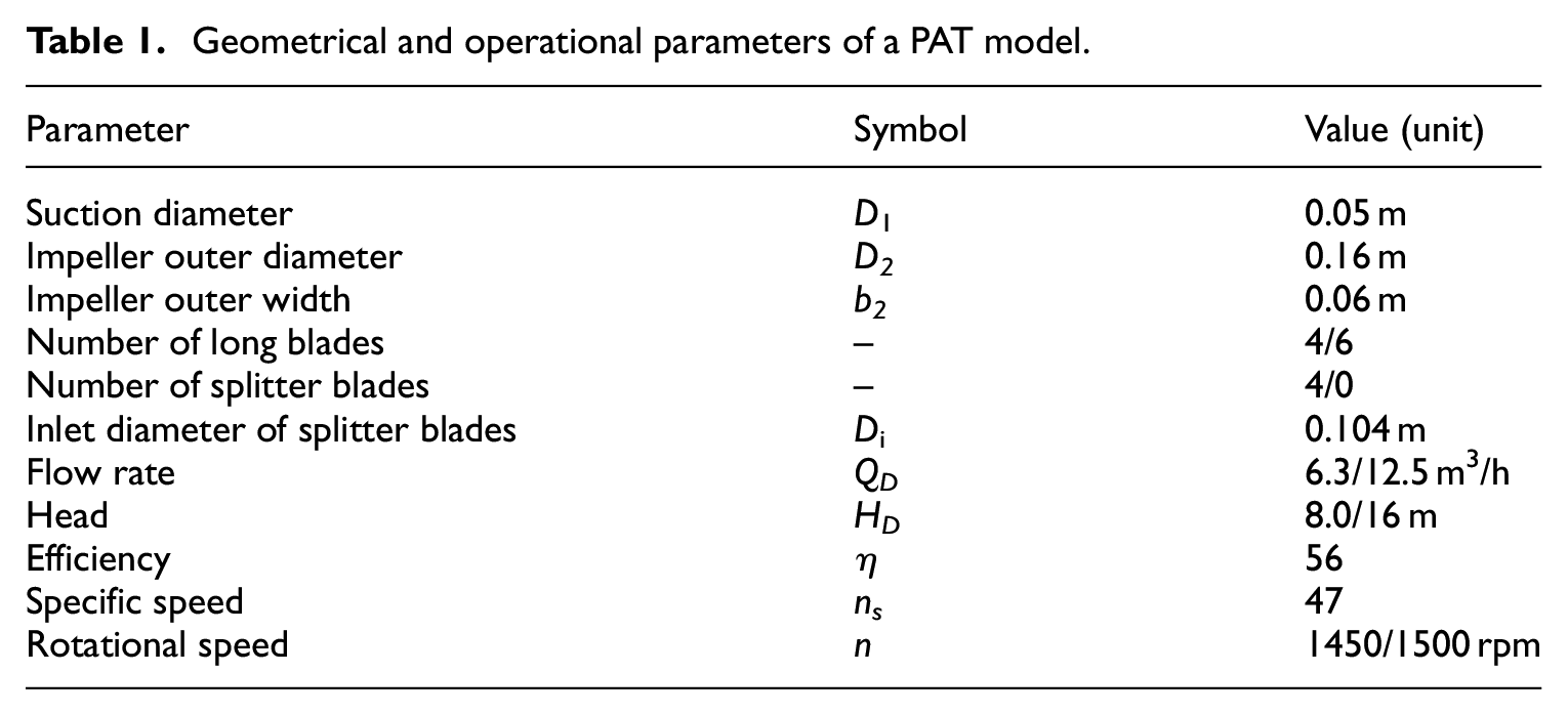
An experiment and Numerical simulation was conducted in this study using two different specific centrifugal pump models with one made up of four impeller blades and four splitter blades and the other with six blades without splitter blades, front and back chambers, volute. The inlet diameter and outlet diameters of both impellers were 104 mm/116 mm, and 160 mm respectively at a designed flow rate Q = 6.3 m3/h, head H = 8.0 m for Scheme 2 without splitter and Q = 12.5 m3/h, head H = 16 m for Scheme 1 with splitter blade, rotational speed n = 1450 rpm and efficiency of 56%, outlet impeller width of 0.006 m, a blade outlet angle of 30°. Summary of the operational and geometric parameters of the selected pump model under study is shown in Table 1. This two impeller models both have outstanding performance in both pump and PAT modes. This experiment is very essential as it helps in validating the CFD numerical results. The experiment was therefore repeatedly conducted until the accurate results was obtained. After the results analysis an increase in absolute velocity of the fluid occurred. Validating the numerical results obtain with the pump mode experimental results is very essential as it assist to understand the PAT mode performance characteristics. The study concludes that numerical simulation provides reliable and conceivable methods to predict the flow and time mean characteristics of PAT.
Geometrical and operational parameters of a PAT model.
CFD set up and Mesh independence analysis
Numerical set up was done using ANSYS CFX code 17.0 in this study to explain the RANS flow equations in a specific pump model. As turbulence models are very essential in simulation, the Shear Stress Transport (SST k-ω) turbulence model was selected for the numerical simulation. This model came from the k-ω and k-ω turbulence models. Advection scheme was set to high resolution with 250C water being selected fluid. Entire surface wall were placed at roughness at control volume of 50 µm. The inlet and outlet boundary conditions remained static pressure of 1atm at inlet and mass flow rate at outlet. Meshing is the process of discretizing of a region under consideration into a set of the control volume. Mesh for diverse parts of the PAT system such as volute casing, impeller, wearing ring, front, and back chambers are generated in this study. CFD calculation method is used since CFD can properly predict the head, power and efficiency of a centrifugal pump. Figure 1 provides a summary of the generated meshes. The hybrid meshes were generated with a mesh generation tool ANSYS-ICEM 17.5 to achieve a stable flow and decrease the backflow. The impeller mesh was generated via tetrahedron unstructured mesh. A hexahedron structured meshing method was applied for the other parts. A mesh independence analysis has been made and from the results a mesh size lesser than 1.65 having a mesh number of 1320620 brought a very slight variations amid the head and efficiency of the pump. Hence the selection of size 1.65 for the generation of the domains as discussed by Daniel et al. 15

Computational mesh domain: (a) Scheme 1, (b) volute tongue, (c) volute, and (d) Scheme 2.
Experimental setup
The pump models selected to operate in reverse mode as turbine (PAT) is tested in an open test loop in a laboratory at the Jiangsu University, China. Figure 2 displays the 2D sketch of the test rig. The flow rate is recorded using electromagnetic flow meter, and the pressure gage is installed at the inlet and outlet to monitor the pressure of the inlet and outlet. Two pressure sensors were installed at both suction and discharge pipes to attain pressure signals with a certainty of 0.12%. An electromagnetic flow meter was used to measure the flow rates with an error of 0.032%. The experiment was conducted to verify the accuracy of the CFD results. The performance tests were done repeatedly to attain a consistent result.

2D sketch of the test rig.
Results and discussions
The comparison of performance curves
An experimental data was matched with unsteady simulation results as shown in Figures 3 and 4. The head and flow rate are standardize using the equations below for the flow rate coefficient φ and head coefficient ψ.


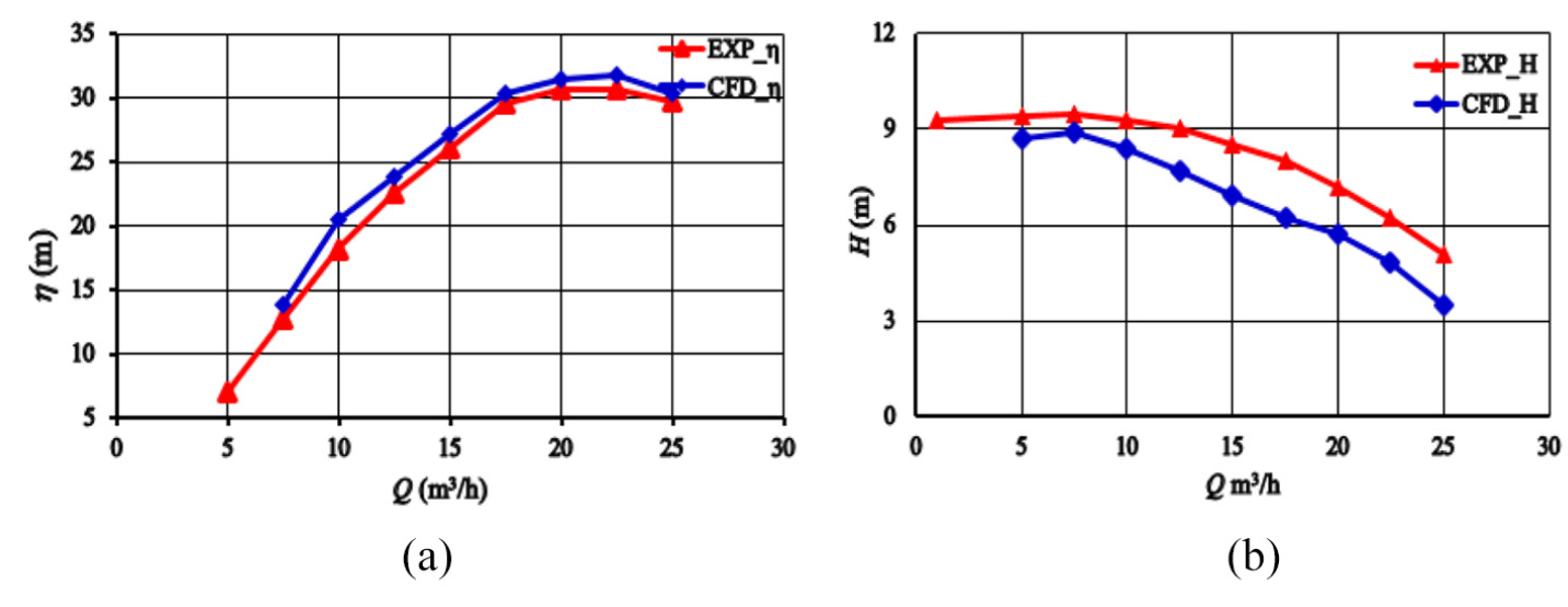
Performance curve of four blade pump model: (a) efficiency versus flow rate and (b) head versus flow rate at np = 1500 rpm.
Performance curve of Scheme 2: (a) efficiency versus flow rate and (b) head versus flow rate at np = 1450 rpm.
The CFD and experiment results of head and efficiency for the two different selected schemes are compared at different flow rates, as shown in Figures 3 and 4. Adding splitter blades makes Scheme 1 have higher head and efficiency at all flow conditions. Scheme 1 has better performance of head and efficiency. It was revealed that both the head and efficiency results from the simulation were in good agreement with the experiment results. Nevertheless minimal error of the flow rate, 17.15 m3/h) and efficiency 20 m3/h) were recorded therefore, adding splitter blades shows an effective influence on the pump performance. However as the flow rate reduced to 15 m3/h), they got larger but acceptable errors no more than 8%. Compared the two schemes, Scheme 1 with splitter showed positive modification for head and efficiency than the Scheme 2 without splitter blade. For that reason, adding splitter blade can increase the workability of the impeller and improve efficiency. In addition, Scheme 2 had a higher head and efficiency at all flow rates due to the splitter blades deviation to the suction side of the main blade. From the results it was observe that minimal error occurred between CFD and experimental results at all operating conditions. This is partly attributed to the neglect of mechanical and volumetric losses in the numerical simulations. The maximum deviation occurred on at the QBEP on the head curve and this makes the numerical results reliable to depend on for further analyses.
Comparison and analysis of PAT performance curves
To evaluate the effects and predict the optimal rotational speed in PAT, different rotational speeds ranging from 1000 rpm to 2500 rpm were studied in PAT modes using two different model impellers with four blades (Scheme 1) and six blades (Scheme 2) to acquire overview characteristics of its operation. Figure 5 shows the head and efficiency performance curves in PAT mode of (Scheme 1). The head increases as the rotational speed increases in turbine mode similar situation are found in Figure 5(a) with PAT impeller (Scheme 1). The efficiency performance curves of the both Schemes as shown in Figures 5(b) and 6(b) were optimal at lower rotational speeds because the conversion of hydraulic energy to mechanical energy is inefficient at higher speeds. The efficiency curves increase as the flow rate increases and decreased after the maximum efficiency, ηBEP. Rotational speed, n = 1500 rpm recorded the highest efficiency of 57.8% for Scheme 1 and 59.3% for Scheme 2 at QBEP among other rotational speeds. However, at n = 2000 rpm, an efficiency decrease of about 2.3% at Scheme 1 and 1.8% at Scheme 2 respectively. Moreover, higher rotational speeds such as n = 2500 rpm, the efficiency recorded at QBEP is about 58.9% which represents about 15.6% decrease in efficiency at both impeller Schemes. Hence, as rotational speed increases, PAT mode performance seems poor thus n = 1250 rpm to 1750 rpm are likely to be optimal rotational speed for PAT operation in both models. Considering the design efficiency of the pump, the Scheme 1 impeller have better efficiency and head than the Scheme 2 without splitter blades though they all perform poorly at rotational speed less than 1000 rpm, patload condition and higher rotational as shown in Figure 5–52b, 53b and Figure 5–3b. It is therefore recommended that Scheme 1 should be selected for PAT operation at a rotational speed between 1500 rpm and 1750 rpm.
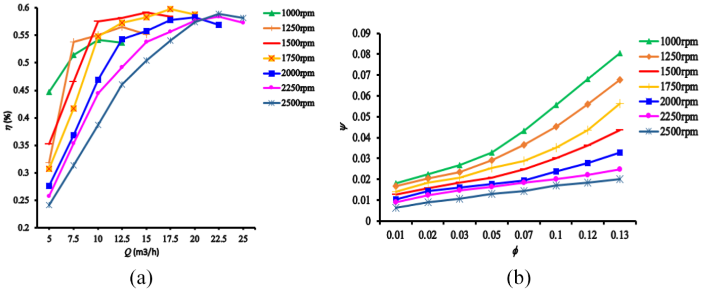
PAT performance prediction under different speed for Scheme 1: (a) head and (b) efficiency.

PAT performance prediction under different speed for Scheme 2: (a) head and (b) efficiency.
Hydraulic PAT performance characteristics curves
The speed of a turbine is determined by the amount of load working with. At constant flow rate and head, the turbine speed decreases when a higher load more than the design load is used by the turbine, with the decrease of the load placed on a turbine whereas the head and flow rate remains constant this principle applies when hydraulic pump is used as turbine at a specified site with a constant flow rate it contribute greatly in determining the performance characteristics of the turbine. As the load on the PAT is further reduced, the speed of the PAT reaches a maximum value that no torque can be delivered by the PAT. This speed is called runway speed. The runaway speed of the PAT is obtained to be approximately 2250 rpm as shown in Figure 7 and the relationship between speed and power at both selected impellers. It can be observed that as the speed of the PAT increases, the power output increases until it reaches 1250 rpm (522 kW) after which the power began to drop progressively. Comparing Figures 7 and 8, PAT efficiency behaves equally as the power output of the PAT. It can, therefore, be concluded that best-operating conditions for selected PAT could be achieved when it operates between 1000 rpm to 1750 rpm with the power BEP recorded at n = 1250 rpm in both schemes. Also both schemes recorded their BEP at 1750 rpm indicating that both schemes performs better at equal flow conditions even though a slight deviation exist been their efficiencies and power.

Power versus rotational speed for selected PAT at Qt = 10 m3/h.
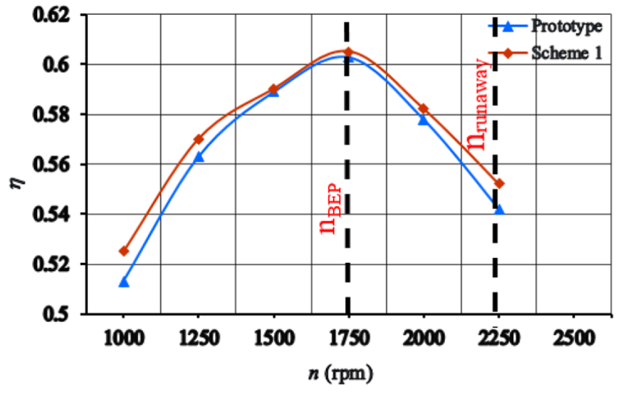
Rotational speed versus efficiency for selected PAT at Qt = 15 m3/h.
Pressure circulation analysis for the selected schemes at different flow rates
Figure 9 shows the pressure distribution at different flow rates at the entire centrifugal pump Scheme 1 model fluid domain and around the impeller flow domain. Scheme 1 model was selected for this analysis since it has been established in both the introduction as the best model to be selected due to its performance in PAT mode as well as better efficiency and head. From the pump mode CFD results, it is observed that pressure increases gradually within impeller passage with maximum pressure recorded at trilling edge. However, pressure side recorded more pressure than suction side of the impeller blade. Again as flow rate increases, the pressure steadily decreases from the inlet pipe and the volute tong region to the suction side and at the leading edge as shown in Figure 9 with Q = 17.5 m3/h having low pressure recorded at the inlet pipe.
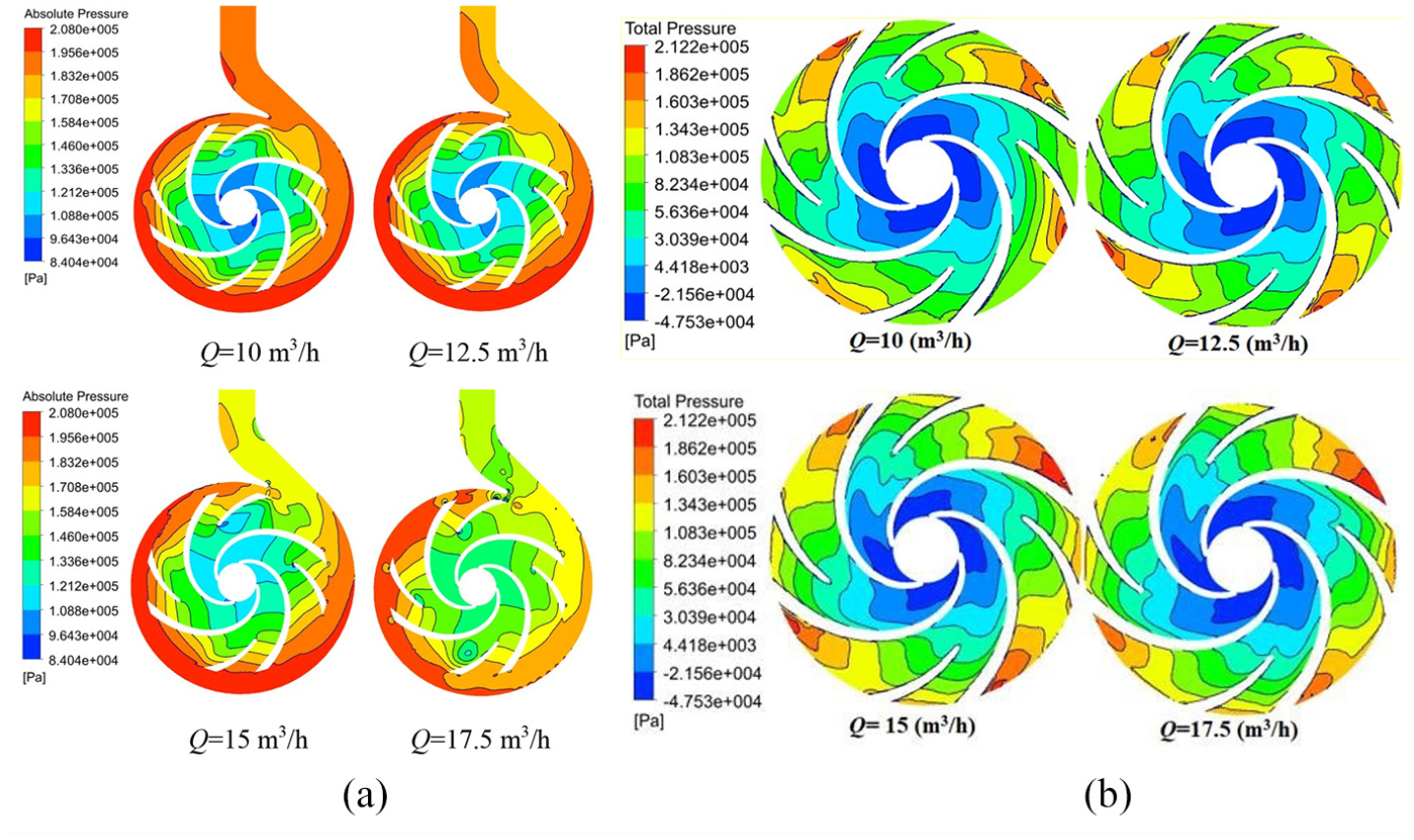
(a) Static pressure distribution for Scheme 1 pump model at different flow rate n = 1750 rpm and (b) static pressure inside the scheme 1 impeller in pump mode.
The overview of the flow shows that the flow exists at the outer radius of the impeller and re-enters at the inner radius. In between the outer and the inner radius of the impeller, a poor exchange of flow exists because of the weak tangential relative velocity, thus generating a stealing flow around that region. The results show that there is an increase in the absolute velocity of the fluid as the fluid flow in the pump impeller. For clearer understanding and picture of flow inside the impeller blade region, the absolute velocity distribution as shown in Figure 9(b) at different flow rate is provided. One can observe from the figure that as flow rate increases and water enters through the inlet pipe and flows along the impeller flow passage, the absolute velocity unremittingly increases in the stream-wise direction along the blade from the leading edge to the trailing edge with the maximum velocity recorded at the pressure side of the impeller blade whereas the suction side and the leading edge recorded the minimum velocity.
Pressure circulation analysis for the selected impellers schemes at different speeds
Performance of the two selected impeller schemes at n = 1500 rpm and n = 1750 rpm have been discussed. The results as shown in Figure 10 indicate that an increase in flow rate decreases the pressure along the impeller region in Scheme 2. However it increase at the inlet pipe and the trailing edge with minimal pressure located at the leading edge. In addition, the pressure drops closer to the exit duct of the suction pipe increases. At the higher flow rate, very high recirculation of flow occurs in the suction side of the blade, although the pressure side has a smooth flow.
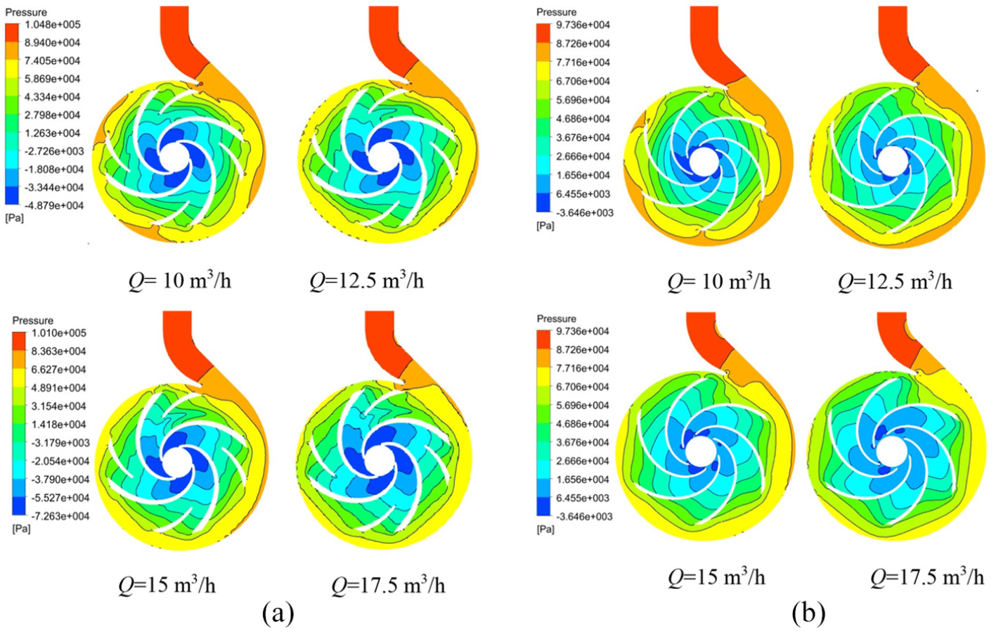
(a) Static pressure distribution of four blade impeller in PAT mode at n = 1750 rpm and (b) static pressure distribution of prototype in PAT mode at n = 1500 rpm.
In comparing the performance of the two schemes it can clearly show in Figure 11 Scheme 1 with splitter blade has higher pressure distribution than the Scheme 2 without splitter which makes Scheme 1 more recommendable to be selected for PAT operation. Total pressure distribution for the two selected impellers schemes at the BEP were compared considering two recommended rotational speeds 1500 rpm and 1750 rpm. For easy analysis, both impeller blades have been labeled 1-4 for Scheme 1 and 1-6 for Scheme 2 according to their direction of impeller rotation. The results show that total pressure inside the impeller blades is asymmetrically distributed in both operational conditions. However, as n = 1500 rpm is showing the maximum pressure distribution compared with n = 1750 rpm in Scheme 1. Nevertheless opposite is found in Scheme 2 where n = 1500 rpm shows the minimum pressure with n = 1750 rpm showing the maximum pressure. The minimum pressure occurs at the back of the impeller blade thus the pressure side whereas the maximum pressure is located at impeller volute tong region on the blade labeled 3 at all operational conditions. In sum Scheme 1 with splitter blade has better performance in PAT than Scheme 2.
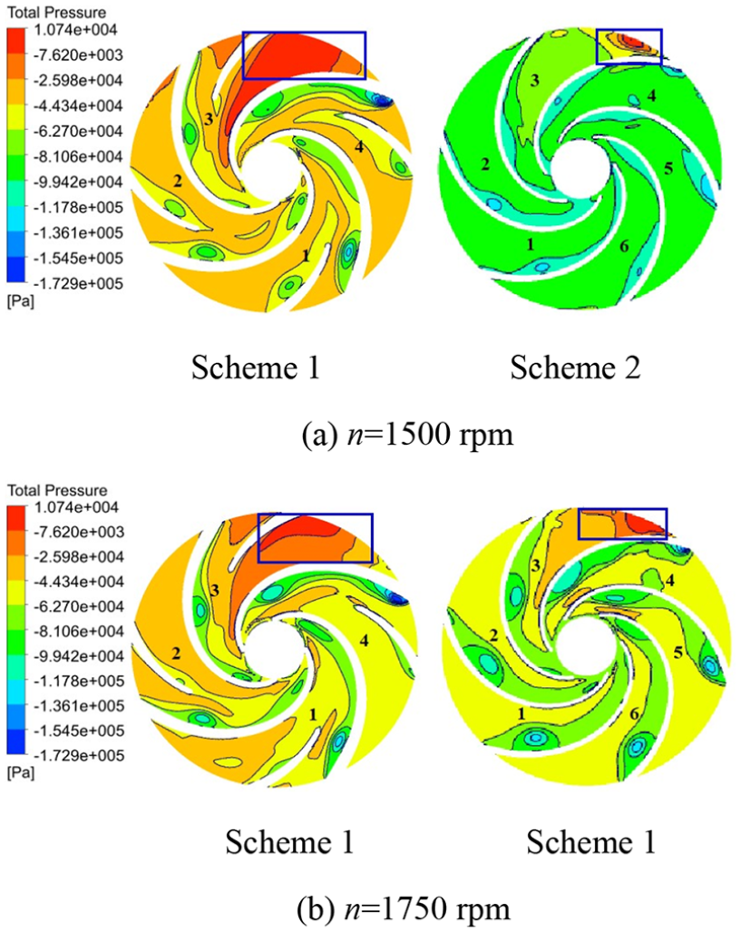
Comparison of total pressure distribution for two PAT schemes at BEP.
Velocity circulation analysis for the selected schemes at different flow rates
Centrifugal pump velocity colored by absolute velocity distribution is displayed in Figure 12, the velocity vector plots were used to analyze the velocity characteristics of the pump impeller. The overview of the flow shows that flow exists at the outer radius of the impeller and re-enters at the inner radius. In between the outer and the inner radius of the impeller, a poor exchange of flow exists because of the weak tangential relative velocity, thus generating a stealing flow around that region. The results show that there is an increase in the absolute velocity of the fluid as the fluid flow in the pump impeller. For clearer understanding and picture of flow inside the impeller blade region, the absolute velocity distribution as shown in Figure 12 at different flow rate is provided.

Velocity distribution for Scheme 1 pump model at different flow rate n = 1750 rpm.
Nevertheless, as the flow rate increases the absolute velocity decreases steadily per the movement of the fluid smoothly to the volute casing and flows through the fluid domain. This decrease is caused by the increase in the cross-sectional area of the volute in the crosswise direction as shown in Figure 12. The minimum velocity was recorded at Q = 17.5 m3/h indicating that pump has a better velocity at flow better 10 m3/h to 15 m3/h with n = 1750 rpm. Figures 13 and 14 shows the velocity distribution at different flow conditions comparing Scheme 1 and Scheme. In Figures 6 to 11, the velocity gradient decreases in Scheme 2 as flow rate increases at speed n = 1500 rpm. However as fluid reached the tongue region velocity intensified indicating that increase in flow rate can influence velocity. Moreover feeble velocity ranging from 0 to roughly 2.7 m3/h was recorded in the impeller passage, whereas the trailing edge of the blades was characterized with high velocity. This effect can be attributed to the direction of the flow without any guide vane into the outlet. At speed n = 1750 rpm, the average velocity distribution within the flow passage declines at all flow rate as shown in Figure 13. A similar condition is viewed in Figure 14 Scheme 2. Generally, the velocity intensity of the flow in the volute is higher than the impeller at all working situations in both speeds n = 1500 rpm and 1750 rpm as fluid energy was extracted thru movement of impeller in the circular direction. Nonetheless, comparing the two schemes at different flow conditions of PAT mode, Scheme 1 has better velocity than the prototype Scheme 2 making Scheme 1 more appropriate to be selected for PAT operation.
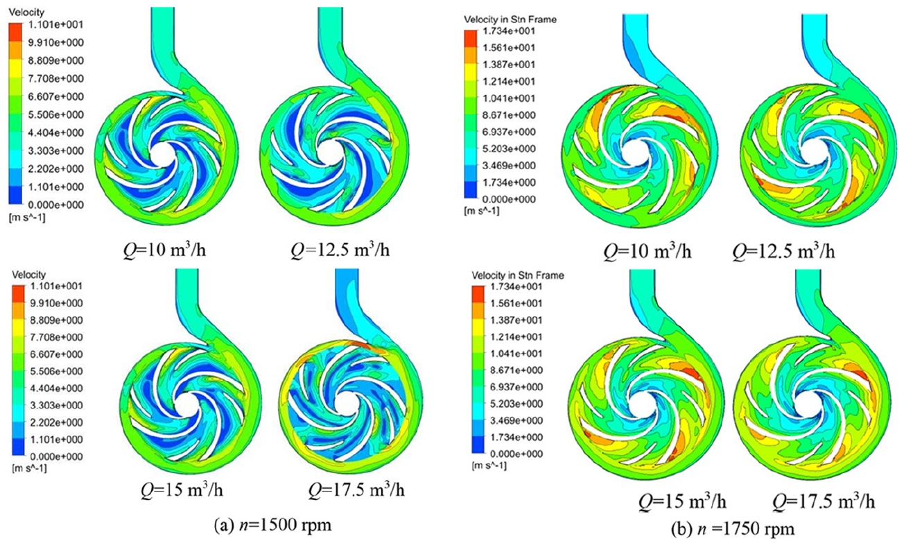
Velocity distribution of PAT Scheme 1 at different flow rate.

Velocity distribution of PAT Scheme 2 at different flow rate.
Conclusion
Both experiment and numerical studies have been conducted to help select PAT for energy generation. A model-specific speed centrifugal pump models are selected for the CFD and Experiment at different speeds and flow rates conditions to verify CFD accuracy. It was discovered that;
The head of the experimental results is slightly higher than the CFD whiles the numerical efficiency is also marginally higher than the experimental efficiency. This could be attributed to the fact that numerical simulation does not consider mechanical and volumetric losses which occur in the actual existing pump. Pump mode experimental data was used to confirm the results for better analysis at all conditions. After the results analysis an increase in absolute velocity of the fluid occurred.
The study concludes that numerical simulation provides reliable and conceivable methods to predict the flow and time mean characteristics of PAT. In comparing the performance of the two schemes it can clearly show that Scheme 1 with splitter blade has higher pressure distribution than the Scheme 2 without splitter which makes Scheme 1 more recommendable to be selected for PAT operation.
The results show that total pressure inside the impeller blades is asymmetrically distributed in both operational conditions. However, n = 1500 rpm is showing the maximum pressure distribution compared with n = 1750 rpm in Scheme 1. Nevertheless opposite is found in Scheme 2 where n = 1500 rpm shows the minimum pressure with n = 1750 rpm showing the maximum pressure. In sum Scheme 1 with splitter blade has better performance in PAT than Scheme 2.
Footnotes
Declaration of conflicting interests
The author(s) declared no potential conflicts of interest with respect to the research, authorship, and/or publication of this article.
Funding
The author(s) disclosed receipt of the following financial support for the research, authorship, and/or publication of this article: Authors of this manuscript will like to show our gratefulness to National Science Foundation of China with grants number 71974081, 71704066, and 71971100 and the Special Funds of the National Social Science Fund of China with grants number 18VSJ038 for their financial supported for this manuscript.