
Abstract
For the difference of rock and soil strength on the tunneling face, curved tunneling, and the top-heavy structure of the main machine forming the complex geological structure, the adoption of uniform thrust system arising from large unbalanced load easily causes cracks and dislocations in the rear segments. Therefore, non-equidistant driving system would be adopted in this composite foundation. This article presents a geometric progression method for layout design of non-uniform thrust system. Based on the force transmission laws of the thrust system, the geometric progression increasing difference model of arranging non-uniform driving system has been proposed. Then, the characteristics of the design method have been discussed in detail. Finally, the model has been applied to a diameter of 9.49 m of tunneling machine with a thrust system of 14 pairs of jacks which has been successfully used in curved tunnel construction in Germany. By adopting the coefficient of variation representing the force transmission performance derived from all thrusts for jacks, it indicates that the performance of the optimized thrust system is better than the original one. The results would provide a theoretical basis for the design of a non-equidistant thrust system with better force transmission performance under working geological conditions.
Introduction
For the characteristics of allowing constructing tunnels in adverse geological conditions including difficult ground conditions as well as tunnels in vulnerable urban areas, tunnel boring machine (TBM) has well-established tunnel construction method recently.1,2 When a tunnel is being excavated, the following two steps in the shield machine are conducted alternatively: the tunneling of the TBM by all jacks in the thrust system applying active forces on the rear segments that simultaneously carries out the excavation of the soil and rock at tunneling face by the rotating cutter-head, and the installation of a segment ring of the shield lining system with simultaneous void grouting at the tail while the machine stops working. 3 Therefore, the design of the thrust system is playing an important role in building a high-quality tunnel with great seal performance. 4
In thrust system of tunneling machine, there are usually dozens of hydraulic cylinders evenly distributed around the shell. The number and type of jacks should be determined according to the tunnel diameter and working geological conditions. Therefore, for different thrust requirements, there may be different number of cylinders in TBMs with the same diameter. In fact, shield tunneling machine would be always faced with complex working conditions, involving heterogeneity of the stratum on tunneling face, sudden load caused by rapid changes of hard and soft stratum in tunneling direction, variable drag torque caused by curve tunneling, and heavy at top for the main machine with an overweight cutter-head. 5 Consequently, in order to prevent the hydraulic cylinder of the thrust system from causing the lining segments to bear excessive unbalanced load, the differential stroke of 50 mm in curved tunnel construction is far less than the theoretical differential stroke of 250 mm in practical engineering application.6,7
It is precise because the non-equidistant system described above has been used in some engineering applications. As shown in Figure 1, a mechanical schematic diagram of earth pressure balance (EPB) with an excavation diameter of 6180 mm has been successfully applied in the construction of subway tunnels in Chinese cities. As can be seen from Figure 1, in the tunneling process, all the cutting with rotating cutter-head cut off the rock and soil on the tunneling face, and then all the tunneling waste pass through a soil pressurized head chamber where the muck pressure is equal to the earth pressure on the tunneling face. Meantime, the whole machine is propelled by jacks in thrust system applying force to the rear lined segments with outer diameter of 6000 mm and inner diameter of 5400 mm. The diameter of the EPB shield machine with a tunneling diameter of 6180 mm is 6150 mm, and its thrust system includes 24 jacks with the stroke of cylinder 2100 mm and the maximum thrust 36,000 KN. As can be seen from Figure 2, due to the overweight head of the main machine, the layout for thrust system of EPB shield tunneling machine has the characteristic of less on the top and more on the bottom under working geological conditions.
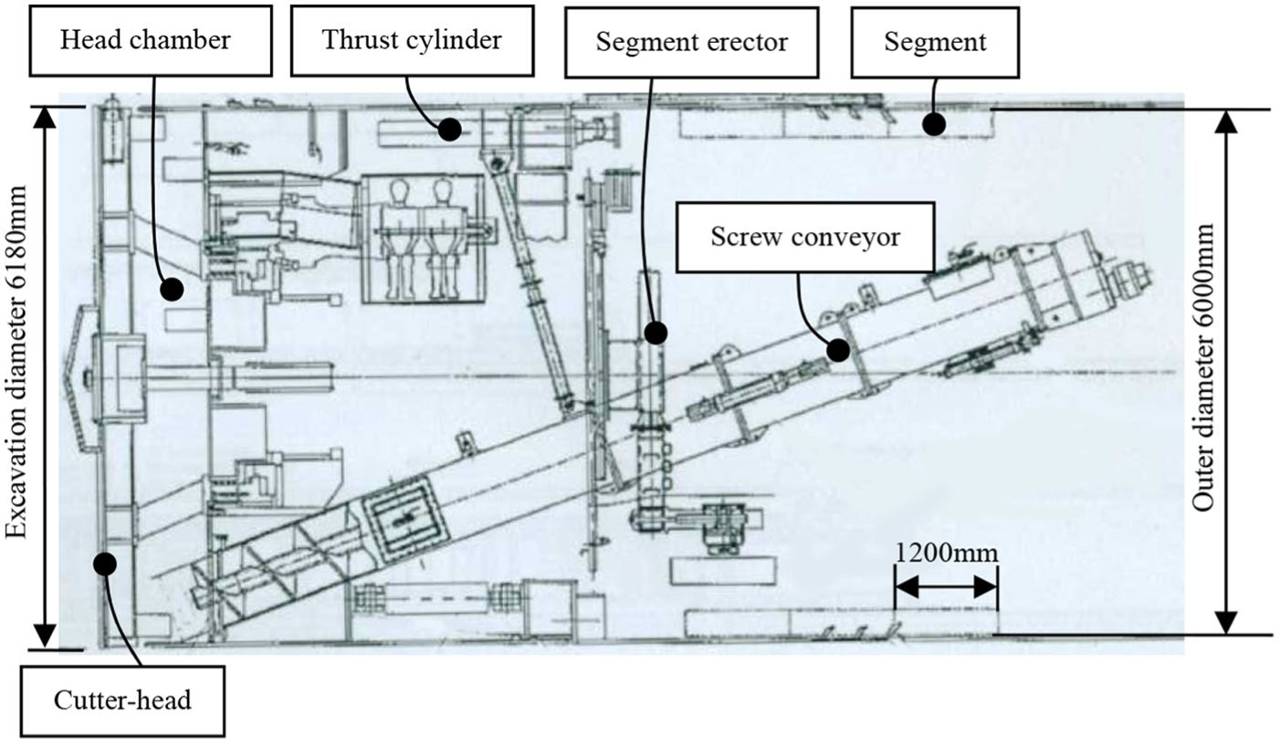
Schematic diagram of EPB with an excavation diameter of 6180 mm.
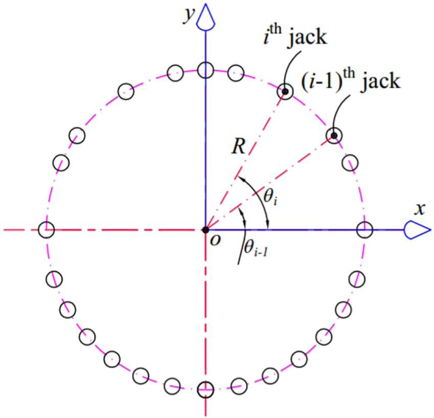
Non-equidistant thrust system for the EPB shown in Figure 1.
Unfortunately, there are few reports on the layout method of non-equidistant thrust system. Researches show that the thrust system with the same number and type of jacks has different force transmission performance, deformation characteristics, and natural frequency characteristics under the same working conditions. The space force ellipse model of force transmission in thrust system has been established. Based on the characteristics of force transmission, under composite foundation, the evaluation methods of thrust ellipse eccentricity for driving system, coefficient of variation (CV), and relative coefficient for thrust of pushing system have been proposed.8–10 The main principle of non-uniform thrust system design has been presented, and a non-uniform thrust system has been found by the Monte Carlo method without considering the uniformity of the layout and engineering application. 11 As a matter of fact, the jacks in thrust system should be evenly distributed as far as possible to avoid the mutual interference between the hydraulic cylinder and other components as well as the major changes in the original design structure. Then, according to engineering requirements for thrust hydraulic cylinder layout, by setting the number of conditions, find out the best layout design.
Aiming at the large number of tunnel cracks caused by the overlarge unbalanced load on the lined segment, the method of geometric progression increase among adjacent phase angles has been proposed in the non-equidistant thrust system of the shield tunneling machine in this article. This method is based on the consideration of the uniformity of force transmission and distribution. On this basis, the characteristics for the common ratio of geometric progression have been studied in detail. Finally, the distribution model would be used to find a non-equidistant thrust system, and the CV assessment has been applied to evaluate the new pushing system. The research result can provide a theoretical basis for the design of the non-uniform thrust system with the capability of the anti-unbalanced load.
Mechanical principles for distribution design
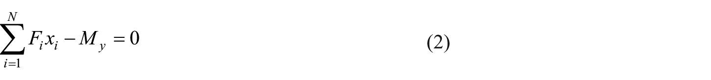
As shown in the Figure 3, all thrusts of hydraulic cylinders in thrust system would overcome the resultant resistance torque Mx and My, and external resultant resistance Fz, and these external loads are caused by complex working conditions, including large difference of strength for rock and soil on the tunneling surface, the overweight of the main machine, curve driving, and different friction between shield machine shell and surrounding rock and soil. In fact, the active forces exerted by the hydraulic cylinder would be directly applied to the rear lined segment ring which is usually composed of several pieces of A blocks, two pieces of B blocks, and one piece of K block. According to Kongshu and Huangong, 12 the center point of the circle arranged by each hydraulic cylinder is taken as the origin of o–xyz in a Cartesian coordinate system. Then, the position parameters of all jacks for any distribution should satisfy the basic mechanical equations
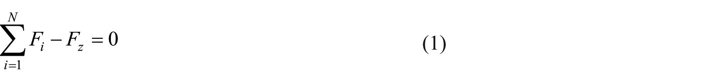

where (xi, yi) represents the layout coordinates of the ith hydraulic cylinder in thrust system,

Simplified 3D model for thrust system.
As depicted in Figure 2, phase angle for parameter of each hydraulic cylinder can be considered as the angle between the o–x axis and the line from the position of one hydraulic cylinder to the layout center point, and coordinate positions xi and yi in equations (2) and (3) can be expressed with arrangement radius R and phase angle


where R notes the layout radius of hydraulic cylinders in the driving system and
The scale of the passive stress on segments makes a direct difference to cracks of segments in a tunnel. 13 Therefore, it is very important to protect segments from cracking by controlling thrusts for all the jacks. Subsequently, in engineering applications, the following equation would be expected. This means that all thrusts for jacks in driving system should be equal to each other under given working geological conditions

Equations (1) to (6) indicate that if layout radius for all hydraulic cylinders R are obtained and all external loads Fz, Mx, and My are deduced from given working geological conditions, the better layout parameters for phase angles
Geometric progression difference of adjacent phase angles
However, studies have shown that many arrangement configurations can satisfy equations (1) to (6) in theory. 15 Clearly, many configurations may fall far short of the requirements for project practices. In engineering practice, the design of shield tunneling machine requires the uniform distribution of jacks and the avoidance of mutual interference between components and jacks. At the same time, the equidistant distribution also reduces the influence on the design change of other parts of the shield tunneling machine. Therefore, all jacks in the thrust system should be evenly arranged as far as possible, while all solutions are satisfied with equations (1) to (6). Subsequently, this article would propose the method of geometric progression solution for layout.
As shown in Figure 4, the external resultant moment Mr can be synthesized by the component moments Mx and My in the x and y directions, and its position angle can be defined as the angle between the resultant moment Mr and the x-axis. Each hydraulic cylinder in thrust system is symmetrically distributed, and its symmetry axis has been shown in Figure 4. The difference for adjacent angles between two adjoining jacks on both sides of the symmetry axis for layout is

Geometric progression arrangement model.
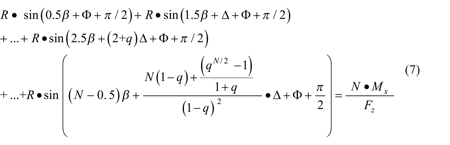
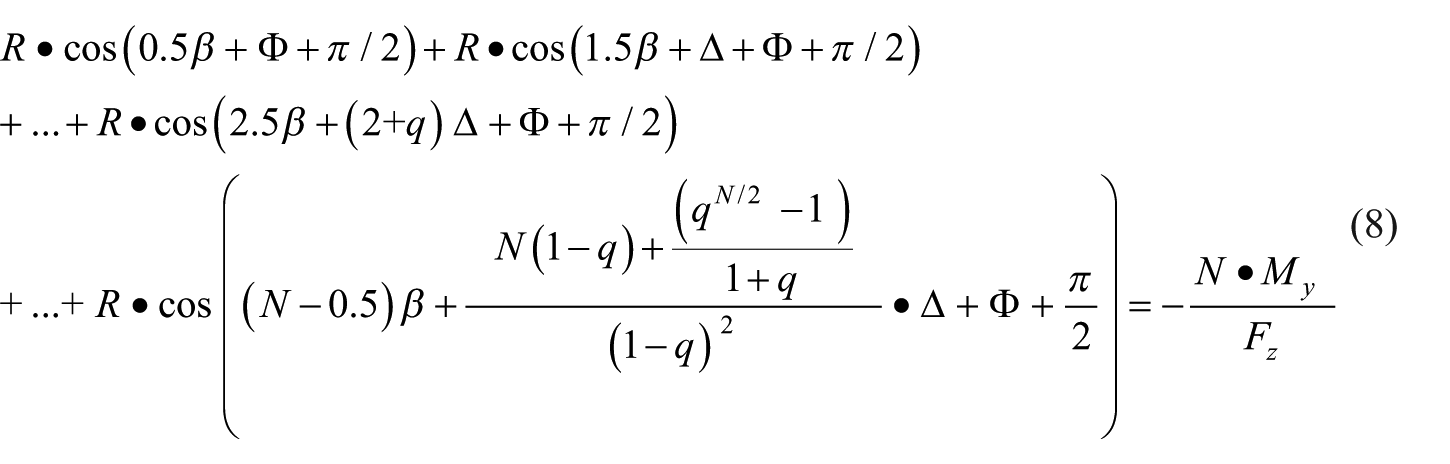
By combining equations (1) to (6), the following equations (7) and (8) can be obtained
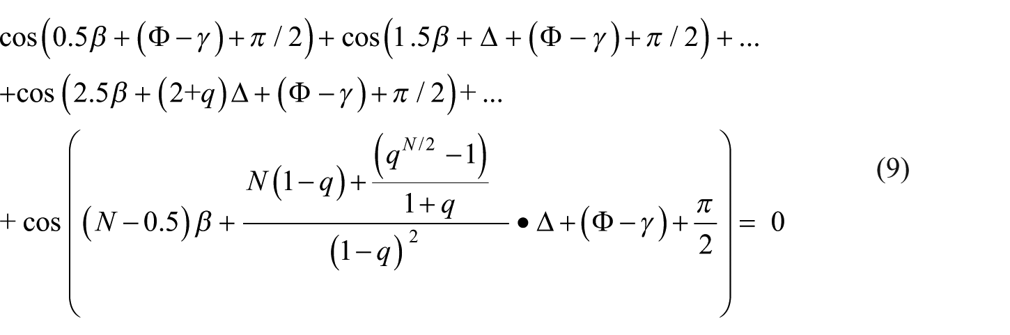
On the ground of Figure 4 and equations (7) and (8), the following equations (9) and (10) can be gained

By comparing equation (9) with equation (10), the following equation (11) can be easily deduced

Equation (11) showed that when the external load Mx and My are calculated, the unknown
Of course, the unknowns
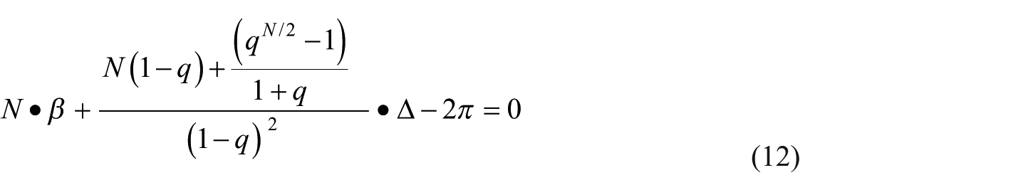
Obviously, by combining among equations (7) and (8) and equation (12), the unknowns


Equations (13) and (14) show that with the symmetry axis for layout shown in Figure 4, the hydraulic cylinder will be evenly distributed with a phase difference
Optimization case study
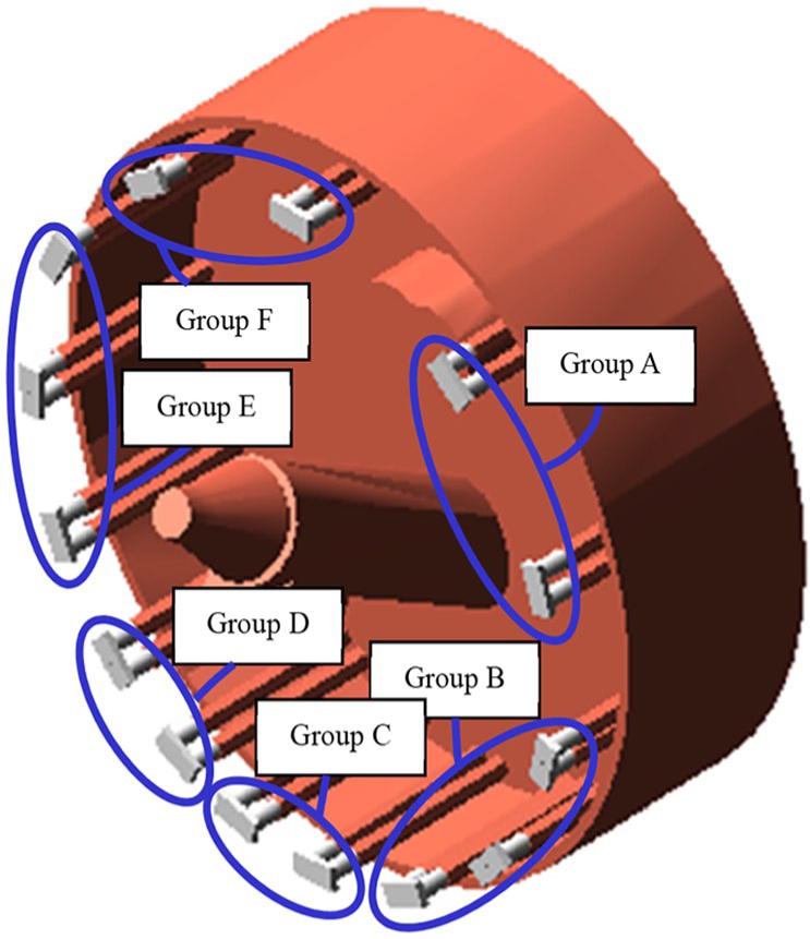
As described in Figure 5, the shield machine with a diameter of 9.49 m has been applied in Wehrhahn-Line (WHL) metro construction of the city of Düsseldorf in Germany, and the thrust system for this machine has layout radius of 4.375 m. There are 14 pairs of jacks in thrust system which are divided into six groups (groups A, B, C, D, E, and F), and the pressure and displacement of each group can be controlled individually. According to Xiaoqiang et al.,
16
the position of the ith pair of hydraulic cylinders in thrust system can be determined by the phase angle

Six-group thrust system.
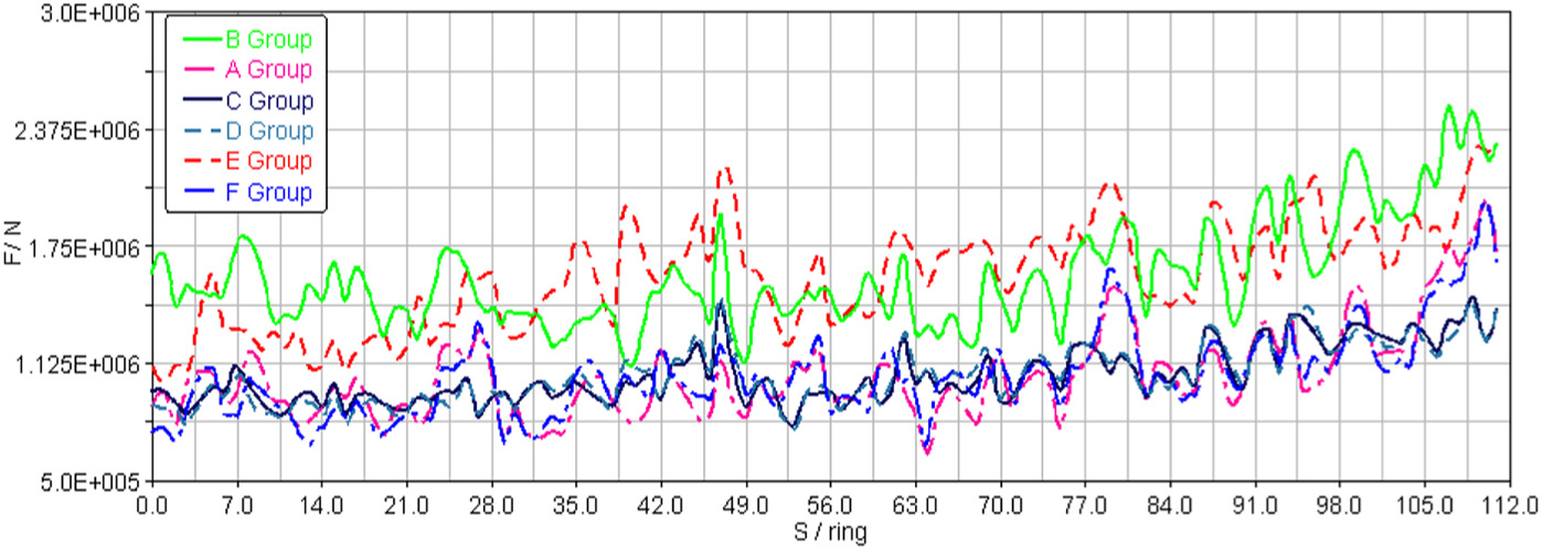
Figure 6 shows the average forces of the six groups measured on a shield tunneling machine for curved tunnel construction with the length of S = 112 rings (1.5 m/ring). According to Kongshu et al. 4 and based on the data shown in Figure 6, the external resultant loads Fz, Mx, and My can be deduced in Figures 7 and 8. It is difficult to distinguish the performance from other thrust systems just from Figure 6. Studies have shown that the CV for force transmission can effectively reflect the mechanical performance for thrust system under mixed ground. 9 The CV for thrust system before optimization has been shown in Figure 9, where the mean value is 0.342 and the maximum value is 0.584, indicating that the force change between thrust systems is close to 60%. This also indicates that in the non-optimized system, there is a large unbalanced load in the rear segments, and the lining segments would be vulnerable to damage under this condition (see Figures 10–13).
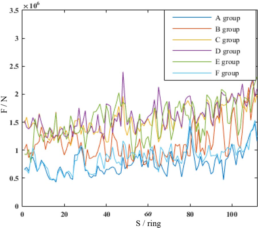
Measured thrust for six groups.

External resistant force, Fz.
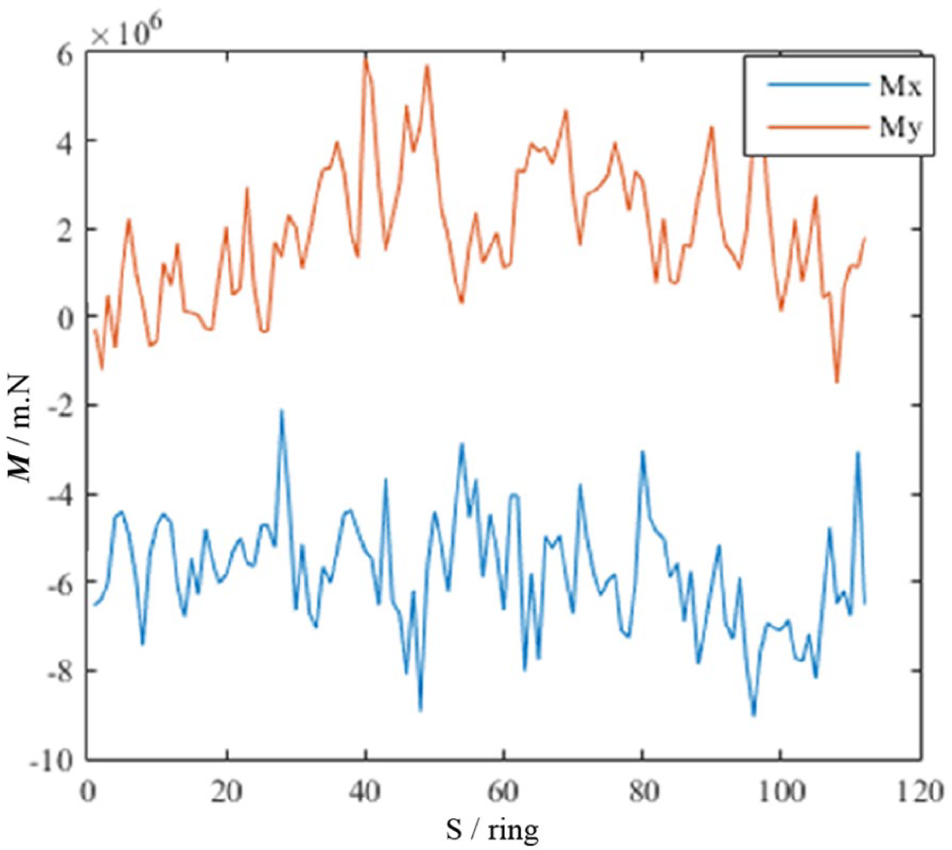
External moments change.
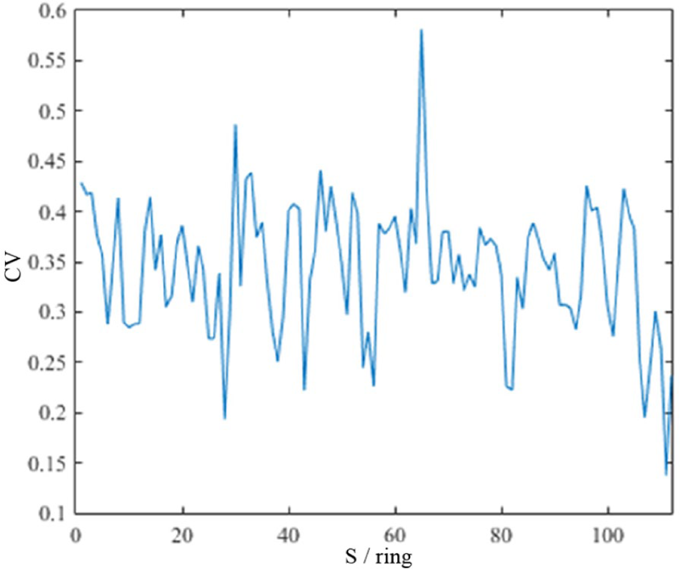
CV for thrust system before optimization.

Change of

Change of Δ with q.
Virtual prototype for optimized thrust system.
Thrusts for six-group jacks.
Therefore, all jacks in the thrust system would be rearranged non-uniformly according to the external forces shown in Figures 7 and 8. Based on the geometric progression mentioned above, let q be evaluated from 1 to 100 in equations (7) and (8), and force parameters can be extracted from the data shown in Figure 6,
4
and then it can be seen that with the increase of q,
Then, the common ratio q would be selected as 1.5 in this article. Introducing q = 1.5 into equations (7), (8), and (12),
Phase angles for pairs of jacks after optimization.

For such a large tunneling machine, it is very difficult to conduct field tests in the new concept stage. Virtual prototype technology should be an effective way to verify the new design theory. On ground of all position parameters of hydraulic cylinders in the optimized thrust system shown in Table 1, a virtual prototype of the optimized thrust system in ADAMS (Automatic Dynamic Analysis of Mechanical Systems) has been established. It can be found that, like the previous system, the new thrust system also has six sets of jacks which are arranged in a different way. Under the same working conditions, all the six groups of thrust would be obtained in ADAMS. By comparing the field test data with the simulation results of ADAMS, it can be seen that because groups B and E have one more pair of hydraulic cylinders than groups C, D, and F in the optimized thrust system, the force for groups B and E with the same number of hydraulic cylinders is greater than that of groups C, D, and F with the same number of hydraulic cylinders. However, the ratio of force for group B to group A is about 1.5, which is equal to the number of jacks in group B to group A. The result shows that the force transmission performance after optimization is better than the original one. According to the simulation result, CV value can also be obtained, as shown in Figure 14. The result indicates that the CV value of the thrust system before optimization was much higher than that after optimization with an average value of 0.0837 and a maximum value of 0.1978. The comparison of the two thrust systems shows that the unbalanced load on the rear segment in the optimized thrust system has been greatly reduced. This system would better prevent the lining segments from crack.

CV values for optimized thrust system.
Conclusion
In order to improve the force transmission performance of the thrust system, a method of rearranging jacks in the thrust system by means of geometric progression increase has been presented. According to the law of force transmission in the thrust system, the geometric progression model of non-uniform system has been established. Then, the characteristics of the model have been discussed in detail. Finally, the model has been applied to the non-eq15 thrust design of the shield tunneling machine with a diameter of 9.49 m and the thrust system of 14 pairs of jacks. The force transmission performance of the optimized thrust system is compared with that of the original one in ADAMS. The following conclusions can be drawn:
When all parameters of a certain shield tunneling machine and tunnel conditions have been given, a non-equidistant thrust system suitable for the shield tunneling machine can be obtained according to the geometric progression increase between adjacent phase angles.
The position of the symmetrical axis for arrangement only depends on the external resultant moment Mr and has nothing to do with the external resultant force, Fz.
With the increase of common ratio q, the values of
Footnotes
Acknowledgements
K.D. gratefully acknowledges the scholarship of the State Scholarship Fund of the China Scholarship Council that allowed him to be a visiting scientist at Ruhr University Bochum and contributed to this work. He also thanks to the scholarship provided by the Collaborative Research Center SFB 837 at Ruhr University Bochum.
Declaration of conflicting interests
The author(s) declared no potential conflicts of interest with respect to the research, authorship, and/or publication of this article.
Funding
The author(s) disclosed receipt of the following financial support for the research, authorship, and/or publication of this article: This research is supported by the Key Laboratory of Road Construction Technology and Equipment (Chang’an University; No. 300102259509), Hunan Province Education Department Key Research Project (No. 18A181), Education and Educational Reform Project of Hunan University of Science and Technology (No. J81202), and Hunan Provincial Natural Science Foundation, China (No. 2018JJ2122).