
Abstract
In order to overcome the low efficiency, high labor intensity and high risk of steel arch support operations in tunnel boring machines, a steel arch looping manipulator with multiple actuators was designed. Firstly, in order to simplify the complex design requirements of the manipulator, an exponential product model was established to analyze the influence of each single joint on the end output, and the manipulator was decomposed into different modules. The design is carried out separately, layer by layer, in the order of actuator—trunk module—branch module. Then, the optimal manipulator is obtained considering the limited space, equivalent flexibility, and joint control accuracy requirements. Finally, a prototype of the steel arch looping manipulator was manufactured and the feasibility of the manipulator was verified by experiments. The design method can provide a reference for the design of multi-actuator manipulator configuration in limited space.
Keywords
Introduction
Hard rock tunnel boring machine (TBM) is a large equipment used for tunnel excavation with the functions of breaking up the tunnel working surface, discharging rock fragments and supporting the tunnel section, which has been widely used in railway, mining, and traffic tunnel projects.1,2 During the construction of TBM, the redistribution of stress in the tunnel surrounding rock may cause deformation, damage or even collapse of the surrounding rock.3,4 Therefore, timely and effective steel arch support is an indispensable work procedure, especially for excavation of poor and broken rock geology.5,6 At present, the installation of TBM steel arches is carried out manually, which requires workers to complete heavy and difficult operations in narrow space and harsh environments. Manual installation of steel arches is inefficient and may cause accidents if the supporting work is not timely and stable. Therefore, it is necessary to design a robot to realize the automatic installation of steel arches, which can improve the efficiency and quality of installation and ensure the safety of personnel.
The installation process of steel arches includes carrying, fixing, bolting and looping. In the looping process, the open steel arches are assembled into rings by hand welding. Its quality directly affects the supporting performance of the entire steel arch. The looping operation has high requirements for accuracy and load-bearing capacity. Therefore, it is necessary to design a multi-actuator looping manipulator, which requires each actuator to achieve specified movements and interrelated trajectories in a limited space.
At present, many scholars have studied the kinematic synthesis of manipulators, focusing on two main aspects: configuration synthesis and dimension synthesis. Configuration synthesis is mainly used to study the kinematic pair types and relative positions, and generally does not involve specific dimensions. Dimension synthesis studies focus on the relationship between manipulator performance and structural dimensions. 7 Most of the manipulators currently used in industry and engineering adopt empirical methods for configuration synthesis. In addition, there have been many innovative configuration synthesis methods, such as Lie group,8–10 screw theory,11–14 position and orientation characteristic set theory,15,16 General-Function set,17,18 and so on. Among these theories, screw theory is the most widely used. It expresses the movement and constraints through a screw system, and determines the movement characteristics through linear operations. However, the configuration description of this method is not intuitive. Based on screw theory, Xie19,20 performed configuration synthesis in the form of linear geometry to make the design process more concise and clear. Dimension synthesis aims to calculate the geometric parameters of the manipulator in order to achieve the specified workspace. Most of the existing studies have turned the dimensioning problem into an optimization problem. 21 However, when the output trajectory is known, both configuration and dimension will affect the performance of the manipulator. In order to accurately obtain the optimal structure of manipulator, both configuration and dimension must be considered. Zhang 22 designed a generalized spherical parallel mechanism based on enumeration and screw theory, and used the D-H method for kinematic analysis. Russo 23 proposed a new method combining path planning algorithm and dimension synthesis to minimize position and orientation errors through configuration synthesis, so that robots with restricted movement can complete a set of prescribed tasks in a constrained environment. Shao 24 designed 12 variable stiffness mechanisms by adding linear springs and using length-adjustable connecting rods. These studies generally start with configuration synthesis and then optimize the manipulator dimension by performance indicators. The steel arch looping manipulator has multiple actuators with more degrees of freedom (DOF). A large number of mechanisms will be generated during the analysis, and separate designs for configuration synthesis and dimension synthesis will lead to great difficulty in design and a large amount of calculation. In order to simplify the design process, a tree design method is proposed for multi-actuator manipulators.
The contribution of this study is the design of a steel arch looping manipulator instead of manual work, which can provide a reference for the design of a multi-actuator manipulator in a limited space. In this article, the complex DOF of the multi-actuator manipulator is decomposed into different parts according to the requirements of each module. The synthesis and preference of the manipulator configurations are achieved step by step according to the actuator—trunk module—branch module sequence. This approach can reduce the design difficulty of multi-actuator manipulators and has important engineering significance.
Design requirements of steel arch looping manipulator
Traditional manual steel arch installation method
Currently, the installation of steel arches is mainly performed manually, as shown in Figure 1. First, the construction workers lifted one steel arch onto the assembly ring of the steel arch installer and fixed it. The assembly ring was then rotated at an angle to place a second steel arch and the adjacent steel arches were bolted together. 25 These processes were repeated until the steel arches were joined into a split ring and the steel arch ring was pushed against the rock wall by the support mechanism. Finally, the steel arch looping operation was performed. The construction workers manually dragged the steel arch ring gap into alignment and opened the steel arch ring gap with a jack to ensure that the steel arch was tight against the rock wall. The steel plate was welded in the gap of the steel arch ring to achieve the final ring, as shown in Figure 2. The dashed arrows indicate the direction of movement.

Traditional steel arch looping construction.

Schematic diagram of traditional steel arch looping operation.
Each traditional steel arch is more than 4 m long and weighs over 200 kg. It is difficult to grasp and drag. In the final looping process, multiple people work together to complete the posture adjustment and widening operation of steel arch, which seriously affects the construction efficiency. In order to reduce the workload of construction workers and improve the quality, efficiency and safety of construction, a steel arch looping manipulator was designed. It is used to replace manual grasping and widening operations, and improve the intelligence and installation efficiency of TBM construction.
The existing steel arch looping method is more suitable for two-handed operation. The process is tedious, which greatly increases the difficulty of manipulator operation. In order to achieve rapid looping of the steel arches, it is necessary to design a new looping method for steel arches.
New looping method of steel arch
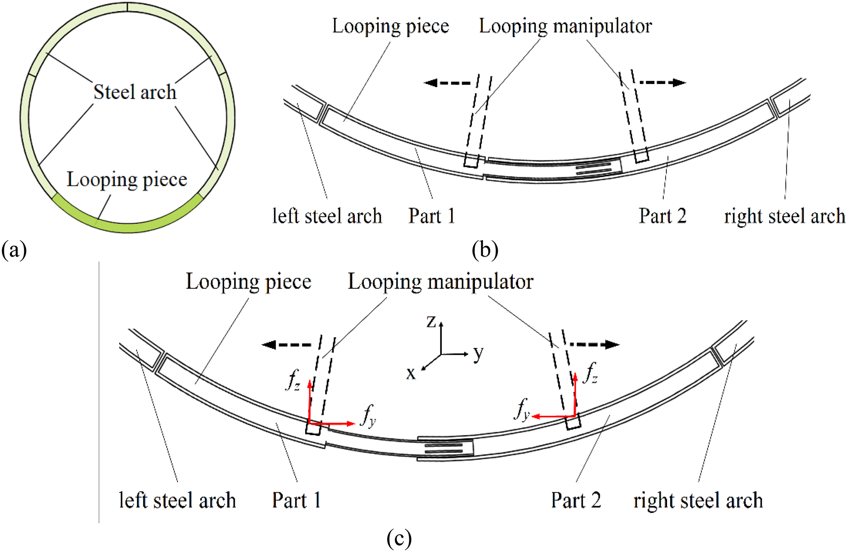
In order to facilitate the operation of the manipulator, a retractable looping piece was designed, as shown in Figure 3. It is divided into two parts. Part 1 is composed of I-beam and U-shaped steel that are fixedly connected, and part 2 is the I-beam. The U-shaped steel of part 1 is embedded in the part 2, and there are two through grooves on it, which are used to initially weld and fix the U-shaped steel to the part 2. In addition, to ensure the quality of the support, the joint seams of both parts need to be fixed by final welding.

Steel arch looping piece structure.
According to the structure of steel arch looping piece, a new looping method is proposed, 26 as shown in Figure 4. The last steel arch of the support ring is replaced by the steel arch looping piece, which is connected to the left and right steel arch, respectively. The manipulator approaches the working position and adjusts the angle to grasp the two parts of the looping piece, respectively. It opens to both sides simultaneously, bringing the steel arch ring close to the rock wall. Finally, the welding manipulator automatically finds the welding seam and completes the looping welding.
New steel arch looping method (a) Composition of support ring (b) Grasp looping pi.
Different from the existing steel arch looping method, the most important feature of the new looping method is that it does not require manual dragging of the steel arch to align the gap, nor does it require taking the steel plate from the outside, as it is a complete ring. Fast looping is achieved through the retractable characteristics of the steel arch looping piece. This method uses robot instead of manual to complete the looping, which improves the looping efficiency and supporting effect.
Design requirements of looping manipulator
In order to make the steel arch looping manipulator more adaptable to the engineering environment, the following design requirements are proposed:
(1) Heavy load: The weight of the looping piece is about 300 kg. Two actuators are set on each branch, respectively, to firmly grasp the looping piece. In addition, the steel arch looping manipulator needs to have sufficient static stiffness to meet the deformation requirements of the looping piece.
(2) Limited space: The space where the steel arch looping manipulator can be moved is the area under the main beam of TBM, as shown in Figure 5, where the rock ballast is stacking at the bottom of tunnel. In order to facilitate the movement and operation of the manipulator in the narrow space, the mounting base of steel arch looping manipulator was set on the bottom surface of the main beam.

Limited space for steel arch looping manipulator.
(3) Accurate end motion trajectory: According to the installation method of the looping piece, the end motion trajectory of steel arch looping manipulator is shown in Figure 6, where 1, 2, 3, and 4 represent the initial position of looping piece grasping point, and 1’, 2’, 3’, and 4’ are the corresponding positions after finishing the operation. Under the action of four actuators, the looping piece extends to both sides and sticks to surrounding rock wall. When the steel arch looping manipulator operates on the looping piece, the grasping posture is required to be adjusted with the deformation of the looping piece in order to accurately control the end movement trajectory of the looping piece. In addition, the steel arch looping manipulator needs to have the function of moving along the main beam and rotating around the vertical direction to ensure the accurate grasping of the looping piece.
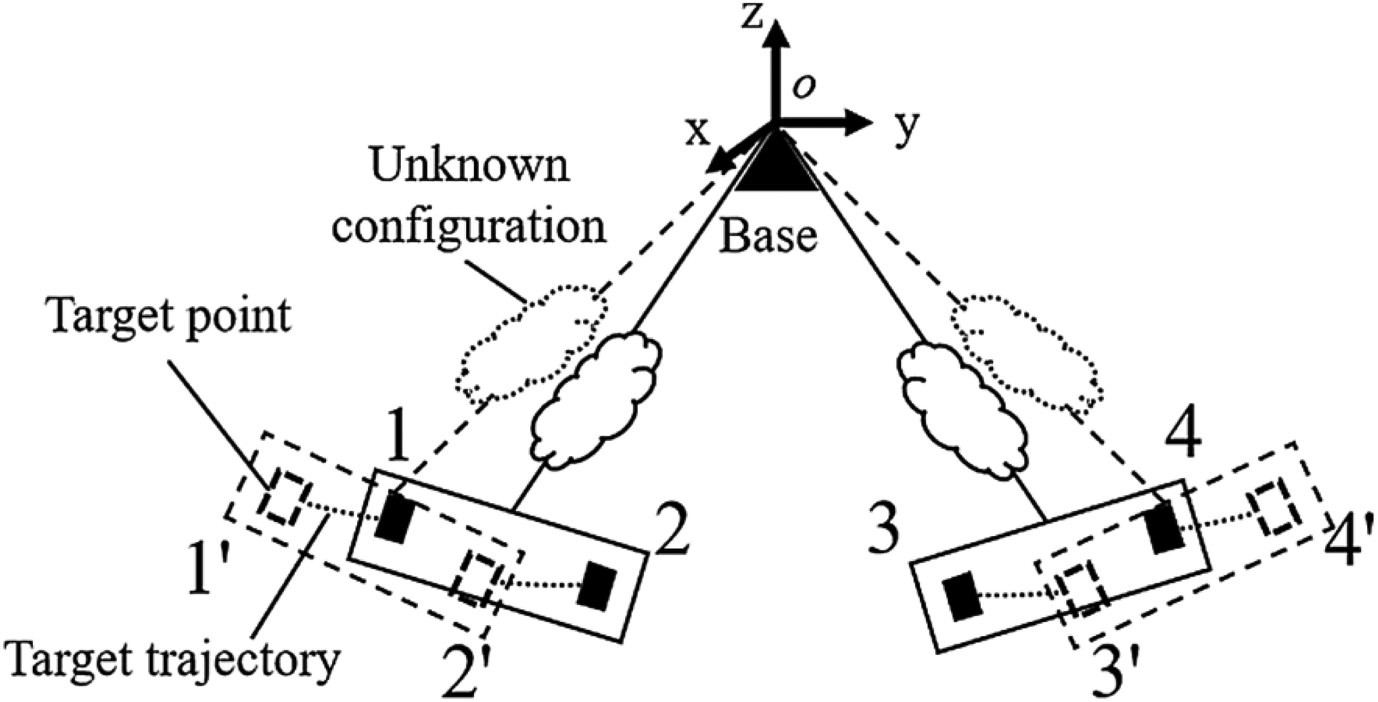
End motion trajectory of steel arch looping manipulator.
Design method of multi-actuator manipulator
Design procedure of multi-actuator manipulator
A tree design principle for a multi-actuator manipulator is proposed, as shown in Figure 7. It includes leaves, branches, and trunks, representing the actuator, branch module, and trunk module, respectively. The design of the manipulator is carried out layer by layer, where the requirements of the manipulator are simplified in the order of leaf-trunk-branch. The design process consists of three steps.
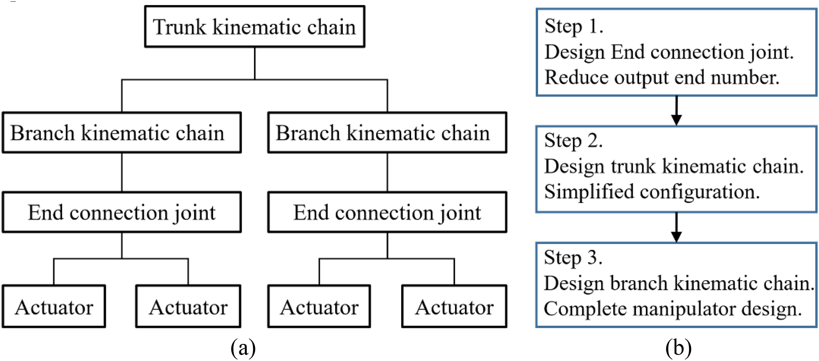
Schematic diagram of multi-actuator manipulator design (a) Schematic diagram (b) Design process.
Step 1: Actuator combination—The end connection joints are obtained based on the posture correlation between the actuators, as shown in Figure 8. It makes the design problem of multi-actuator manipulator simplified to the design problem of end connecting joints. According to the DOF requirements of end connecting joints and atlas method, the kinematic chain of the manipulator can be obtained after deducing the DOF space and the same-dimensional subspace. The transformation types can be divided into three conditions based on the relationship between actuators:
If the relative distance and angle of two actuators remain unchanged, there is no end connection joint. The two actuators can be fixed, as shown in Figure 8(a).
If the relative distance of two actuators remains unchanged and the angle changes, the end connecting joint can be a revolute joint, as shown in Figure 8(b).
If the angle of two actuators remains unchanged and the relative distance changes, the end connecting joint can be a prismatic joint, as shown in Figure 8(c).

End connecting mechanism form (a) Fixed constraint (b) Revolute jiont constraint (c)Prismatic joint constraint (a) Fixed constraint (b) Revolute jiont constraint (c) Prismatic joint constraint.
Step 2: Trunk module design—Firstly, the influence of each joint on the trajectory of end connecting joints are analyzed using the product of exponentials (POE) formula, and the joints that are not related to the working action are regard as the trunk joints. Then, the trunk joints are connected into trunk module in different arrangement sequences based on the DOF requirements. The space position change law of the main joint during the operation of the manipulator is analyzed, and the trunk module best suited to narrow workspace is selected. Trunk module plays the role of moving and adjusting manipulator in the early stage, driving all end connection joints to perform synchronous movement.
Step 3: Branch module design—The branch module can be obtained by connecting the joints related to the working action. Combined with end trajectory requirements and motion space constraints, the link length range and joint motion range of different branch modules are deduced. On this basis, the static flexibility model of the branch modules is established, and the flexibility change curve in the whole working process is analyzed. Finally, the optimal branch module is obtained based on the equivalent flexibility and joint motion accuracy requirements.
Dimension constraints of existing mature joints
The joint structure used in large heavy-load engineering equipment is simple and reliable, which can be classified into revolute joints and prismatic joints. Slewing base and externally driven revolute joint are the most popular revolute joints, as shown in Figure 9(a) and (b). The slewing bases are generally applied to the manipulator trunk joint, which can achieve a larger rotation range by gear drive. While the externally driven revolute joints are driven by cylinders and have an effective rotational angle range o [0,90°]. As for prismatic joints, sliding rails and telescopic arms are the most popular forms, as shown in Figure 9(c) and (d). The slide rail is mainly installed on the rack, which takes up a large space and is driven by a cylinder. In the telescopic arm, the length of the inner arm is smaller than that of the outer arm. In the design process, the effective displacement
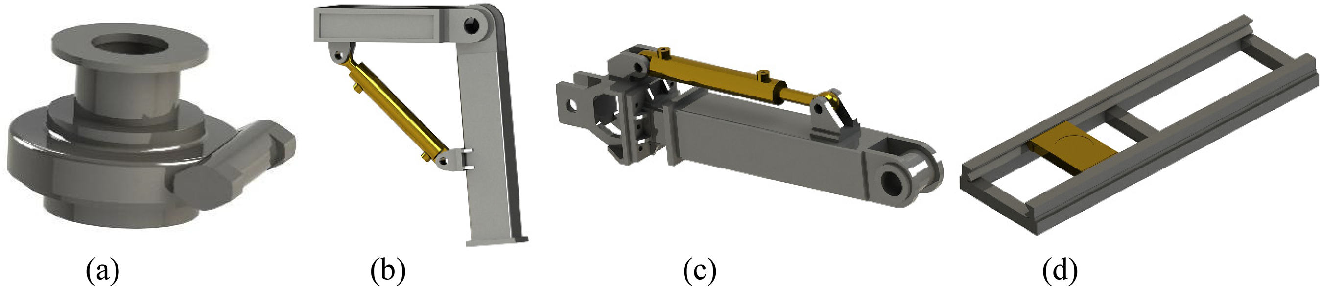
Common joint types in engineering (a) Slewing base (b) Revolute joint (c) Telescopic arm (d) sliding rail.

Dimension constraints of telescopic arm.
Design and kinematic modeling
Actuator combination
Each side of steel arch looping manipulator is grasped by two actuators. Since the relative position between the actuators and the looping piece remains constant, the relative distance between the actuators on the same side is also constant. During the operation of the looping piece, it will be stretched and moved outwards, so the angle of the actuators on the same side will change. It can be seen from Figure 8 that the end connection joint is a revolute joint, which is set between the two actuators.
The end trajectory of the steel arch looping manipulator is in the same plane, and the end connection joint needs to be able to move freely in this plane. Considering the motion and rotation requirements of the manipulator comprehensively, the DOF space of the end connection joint can be obtained according to the atlas method.27,28 Using the functional equivalence principle, the same-dimensional subspaces of the DOF space are deduced to obtain a large number of configurations, as shown in Figure 11, where the double-arrow line represents the prismatic DOF and the straight line without arrow represents the revolute DOF. The coordinate system of DOF space and the same-dimensional subspace below refer to the direction of this coordinate system.

Configuration synthesis based on traditional atlas method.
It can be seen that the traditional atlas method can also realize the configuration synthesis of the multi-actuator manipulator, but a large number of configurations will be obtained, which causes greater trouble for the subsequent dimensional optimization. Therefore, according to the tree design method, the manipulator is divided into multiple parts for analysis, which greatly reduces the computational effort.
Trunk module design
According to the POE formula, the position of the end connection joint under the action of each joint can be obtained. The inertial coordinate system {S} is established on the base and the tool coordinate system {T} is established on the end connection joint. The POE formula for the forward kinematics of the manipulator is as follows 29 :

where
The i-th revolute joint

According to the same-dimensional subspace, it can be obtained that the axis direction of the revolute joints are all along the x-axis or z-axis, and the direction of the links are all along the y-axis or z-axis. The screw of each joint is calculated as follows.
When the i-th joint is a revolute joint, the

The forward kinematics of a manipulator driven by an x-axis or z-axis revolute joint is obtained as follows.


According to equation (5), when there is no linkage in y-axis direction (as in the first two same-dimensional subspace in Figure 11), we can get
When the i-th joint is a prismatic joint, the

The forward kinematics of a manipulator driven by the prismatic joint in the x-axis, y-axis, or z-axis direction can be obtained as follows.

It can be seen that the joint Px will cause the end of the manipulator to be displaced in the x-axis direction. Since the looping trajectory lies in the yz plane, joint Px is not a component joint of the branch module. Therefore, joint Px is also a trunk joint.
The joints Rz and Px are used as the trunk joints connected to the base. The optional configurations of the three trunk modules are shown in Figure 12, and their forward kinematics are derived using the POE formula.

Trunk module optional configurations (a) Trunk module I (b) Trunk module II (c) Trunk module III.
Trunk module I:

Trunk module II:


Branch module design
After removing the trunk joints, the optional configurations of the branch module are obtained by the atlas method. During the operation of the branch module, the trunk joint is fixed, so the inertial coordinate system {SB} of the branch module is established at the connection position between the trunk module and the branch module, and the tool coordinate system {TB} of the branch module is set at the end of the manipulator, as shown in Figure 13.

Branch module optional configurations (a) Branch module 1 (b) Branch module 2 (c) Branch module 3 (d) Branch module 4
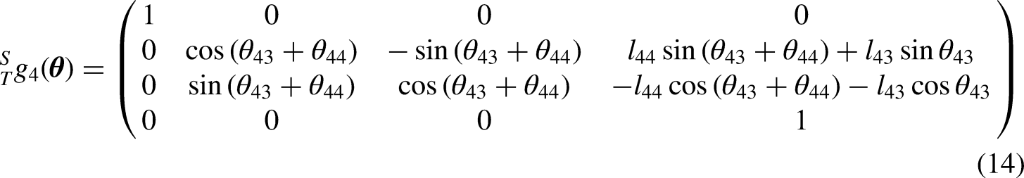
According to POE formula, the forward kinematics of the four types of branch modules can be obtained as follows.


Structural optimization
Constraints of branch module
The end trajectory of steel arch looping manipulator is displaced outward along the bottom arc so that the looping piece is tight against the rock wall. The branch module will be arranged with a slight offset to one side, limited by the assembly requirements. The offset size and the outward displacement can be roughly counteracted. Therefore, an end constraint function for the branch module during operation is proposed with the aim of simplifying the link size model.

The y’ and z’ of the four branch module models are substituted into equation (15), and the dimensional constraints of the existing mature joints are combined to obtained the parametric relationships between branch module links and joints in Table 1 and Figure 14. In Table 1,

Branch module working diagram in limited space (a) Branch module 1 (b) Branch module 2 (c) Branch module 3 (d) Branch module 4.
Branch module link and joint parameter constraints.

For branch module 3,
Branch module flexibility model establishment
When steel arch looping manipulator completes the looping operation, the branch module limits the link length and joint parameters, as shown in Figure 15. All these factors have an influence on the static flexibility performance of the branch module. It is assumed that the link has an elastic modulus
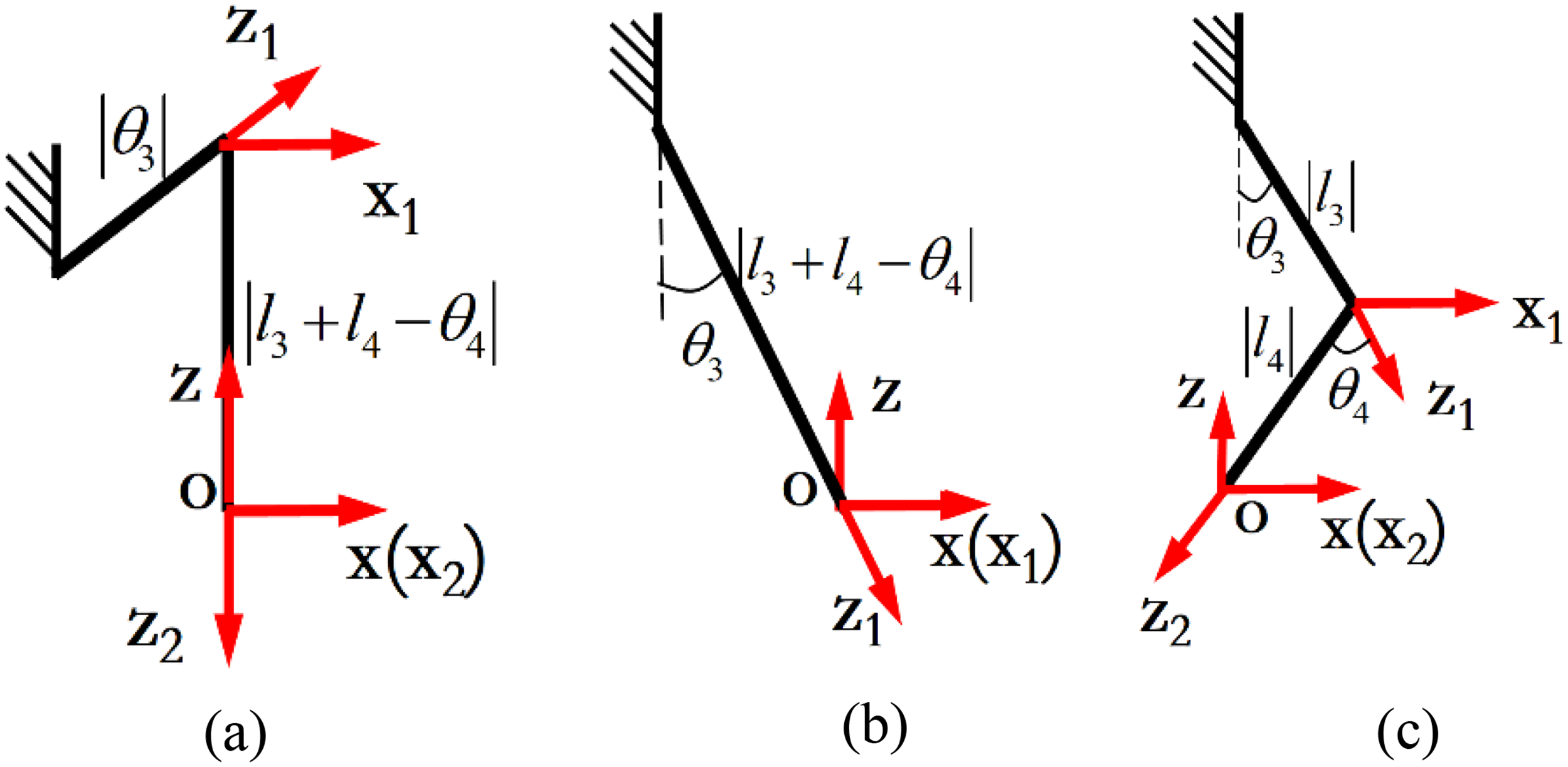
Branch module coordinate system (a) Branch module 1 (b) Branch module 2 (c) Branch module 4.
Based on the classical beam theory,
30
the flexibility matrices of the links are obtained and transformed to the same reference coordinate system. Then, these flexibility matrices are added to obtain the flexibility matrix

where,
The actual load of the steel arch looping manipulator is shown in Figure 4(b), which can be expressed as

where
Similarly, the end flexibility of branch module 2 in the y-axis and z-axis directions is

where
The end flexibility of the branch module 4 in the y-axis and z-axis directions is

where,
Discussion
In order to adapt to the harsh environment such as heavy load, darkness, and humidity in tunnel engineering, the manipulator must have good structural stiffness. In addition, in order to improve the end precision of the manipulator, the sensitivity of the joint input parameters to the end output should be reduced, that is, the control precision requirement of each joint should be low.
During the looping process, the branch module mainly overcomes the frictional force within the looping piece and the reaction forces from the surrounding rocks. The loads at the end of the branch module are mainly the forces along the y-axis and z-axis, as shown in Figure 4(c). According to the actual situation of the project,
The parameters in equation (17)–(19) can be obtained from Table 1, that is

Joint motion curve of branch module (a) Branch module 1 (b) Branch module 2 (c) Branch module 4.
It can be seen that the joint motion curve of branch module 1 has a decreasing trend with a curvature of −0.46 to −0.05. In the early stage of operation, the control precision requirement for L2 is very high. It shows that when L1 increases by 10 mm, L2 needs to decrease by 0.5 mm which is difficult to control. The curve of branch module 2 has an increasing trend with a curvature of 2.9 to 11.4 mm/°. At the beginning of the operation, the curvature is the lowest. When
According to equations (17)–(19), the flexibility curves of the three branch modules can be displayed in Figure 17.

Flexibility curve of branch module (a) Branch module 1 (b) Branch module 2 (c) Branch module 4.
As shown in Figure 17, the variation curve between flexibility and travel distance of branch module 1 shows an increasing trend, where the maximum value occurs at
Considering the flexibility variation across the workspace, the equivalent flexibility of branch module 1 is

where W is the workspace.
The equivalent flexibility of branch module 2 is

The equivalent flexibility of branch module 4 is

In summary, among the three branch modules, branch module 2 has the lowest requirements for joint motion control precision and is suitable for engineering. Branch module 1 has the highest end flexibility, while there is not much difference between branch modules 2 and 4. Therefore, branch module 2 was selected as the optimal kinematic chain.
Prototype test
According to the optimal configuration selection, the structure of steel arch looping manipulator was obtained by combining the trunk module 1, branch module 2, and revolute end connecting joint, as shown in Figure 18(a). A prototype of steel arch looping manipulator was designed and manufactured, which was applied to the TBM. The end actuators were controlled by hydraulic cylinders for grasping, adjusting, and looping actions. The prototype consists of two telescopic arms, each of which is connected to two actuators with a revolute joint. Both actuators grasp the looping piece simultaneously to ensure the stability of grasping action.

Steel arch looping manipulator (a) Configuration (b) Three-dimensional model (c) Working process diagram.
As shown in Figure 19, the prototype of the steel arch looping manipulator was used for the steel arch looping experiment. 28 Firstly, the position and angle of the steel arch looping manipulator were adjusted. Immediately thereafter, the actuators were opened and the telescopic arms were gradually extended to drive actuators close to the looping piece. Then, the actuators were gradually closed until the looping piece was tightly grasped. Under the action of the cylinders, the actuators grasped the looping piece and spread it to both sides until it was in complete contact with the rock wall. Finally, the welding manipulator automatically welded the looping piece to realize the final loop formation of the steel arches. The action time of each step and the average speed of the joints are shown in Table 2. The speed of step 2 is set to 0.005 rad/s for fine-tuning.

Prototype experiment (a) Position Adjustment (b) Extending (c) Fine tuning and grasping (d) Moving to both sides (e) Automatic welding.
Relevant data of steel arch looing experiment.

In step 5, the Rx1 joint moved with an average velocity of 0.01 rad/s, so the velocity of the Pz joint was

where t is the start time of step 5.
The experimental results show that the steel arch looping manipulator can accurately complete the grasping and looping operation of the looping piece under the control of cylinders. During the looping operation, no slippage occurred between the actuators and the looping piece, which indicates that the looping piece was grasped tightly. The looping piece was close to the cave wall, which satisfied the supporting requirement of the looping piece. In general, the designed steel arch looping manipulator is feasible for looping steel arches.
In addition, the average time for the entire looping installation was 8.6 min, while the traditional manual looping installation of steel arches generally takes 10 to 15 min. The efficiency of the steel arch looping manipulator is about 1.5 times higher than manual operation. It can improve construction efficiency and ensure construction safety.
Conclusion
A retractable looping piece structure and a corresponding looping method for steel arches, which is easy to operate robotically, are proposed. Compared with the existing looping method, the steps are simpler and the support efficiency can be improved.
A tree design method for multi-actuator manipulators in limited space is proposed. The DOF requirements of the manipulator are simplified layer by layer in the order of actuator—trunk module—branch module, and the complex manipulator is decomposed into multiple modules to be designed and optimized separately, which greatly reduces the design difficulty of the complex manipulator with multiple actuators.
Based on the tree design method, a four-actuator steel arch looping manipulator was designed with limited space, stiffness requirement and control difficulty as indicators. Based on the results of the optimal configuration, a prototype of the steel arch looping manipulator was developed. The prototype test shows that the proposed manipulator can successfully complete the steel arch looping process. It can replace the manual grasping, spreading and welding of steel arches, solving the low efficiency and high-risk problem of manual looping of steel arches. In addition, the looping installation process takes 8.6 min, which is about 1.5 times more efficient than manual operation.
The proposed method is applicable to manipulators where each module can be moved independently. It will have limitations when there is coupled motion between the trunk module and the branch module. This will be further investigated in future work.
Footnotes
Availability of data and materials
All data generated or analyzed during this study are included in this published article.
Declaration of conflicting interests
The author(s) declared no potential conflicts of interest with respect to the research, authorship, and/or publication of this article.
Funding
The author(s) disclosed receipt of the following financial support for the research, authorship, and/or publication of this article: This work was supported by the special funding support for the construction of innovative provinces in Hunan Province, Independent Exploration and Innovation Program of Central South University (grant number 2019GK1010, 2022ZZTS0633).
Author biographies
Yuanfu He is a PhD candidate and is mainly engaged in the study of mechanical design and robotics.
Mei Yang is a postgraduate and is mainly engaged in the research of tunnel and underground engineering.
Zhen Xu is a senior engineer and is mainly engaged in the research of the design and manufacture of tunnel boring machine.
Shenyuan Li is a senior engineer and is mainly engaged in the study of the design and manufacture of tunnel boring machine.
Bowen Zhang is a master and is mainly engaged in the study of mechanical design.