
Abstract
This study aimed to provide a description of the continuous recording of the true load regime experienced during daily living by the abutment of a trans-femoral amputee fitted with an osseointegrated fixation. The specific objectives: (i) To present an apparatus and a procedure allowing recording of the load regime, and (ii) an example of the raw data and six performance indicators of the usage of the prosthesis obtained with this method. A subject was monitored for a period of 5 hours as he went about his daily activities. The load regime was directly measured and recorded using a commercial transducer and data logger. The overall load profile presented alternative periods of variable length of inactivity (64%) and activity (36%), respectively. The maximum load applied on the mediolateral, anteroposterior and the long axes represented 21%, 21% and 120% of the body weight, respectively. The anteroposterior, mediolateral and long components of the impulse were 395 kN.s, 359 kN.s and 2,323 kN.s, respectively. The amputee generated a total of 2312 gait cycles of the prosthetic leg, giving an approximate overall cadence of 8 stride/min. Preliminary outcomes indicated that the proposed method was an improvement on the current techniques as it provided the true loading and actual usage of the prosthesis during daily living. This study is a stepping stone in the development of future affordable, on-board and user-friendly load recording systems that can be used in evidence-based practice.
Keywords
Introduction
Researchers have recently developed an innovative surgical method of attachment of the prosthesis for trans-femoral amputees that is based on direct skeletal anchorage. In this case, the socket is replaced by an osseointegrated fixation (Aschoff and Grundei 2004). One of the most advanced teams has developed a fixation including an implant and an abutment (Robinson et al. 2005; Ward and Robinson 2005). The implant inserted into the shaft of the femur develops a firm biological bonding with the bone, named osseointegration. The abutment is a rod of titanium that penetrates the soft tissue. One end is connected with the intraosseous implant while the other protrudes from the stump, allowing attachment of the external prosthesis.
So far, this technique, experienced by over 100 trans-femoral amputees worldwide, has proved to be a successful alternative for amputees who experience complications in using a conventional socket-type prosthesis due to short residuum and/or soft tissue problems (Brånemark et al. 2001; Sullivan et al. 2003). The absence of a prosthetic socket can alleviate the skin problems and stump pain. This technique has contributed to the significant improvement in the quality of life of trans-femoral amputees (Sullivan et al. 2003). Amputees can have improved sensory feedback, referred to as osseoperception (Brånemark et al. 2001). External components of the prosthesis can be attached and detached from the abutment easily. Amputees can enjoy a greater range of hip motion and better sitting comfort compared to socket-type prostheses (Hagberg 2004; Hagberg et al. 2005).
Most amputees can also walk further and be more active than when using a conventional prosthesis (Sullivan et al. 2003). However, some amputees are dissatisfied with the components of their artificial leg, which were initially designed to be fitted with a socket (for example, limited range of knee flexion). In addition, some occasional mechanical failures of the fixation have been reported. These have occurred essentially due to a bending of the abutment following a fall of the amputee (Sullivan et al. 2003). The ability of the abutment to bend is to protect the bone from overload.
These problems are directly related to the daily usage of the prosthesis. Consequently, an increased understanding on the load regime during daily activities will help to optimize the strength of the abutment and future developments of prosthetic components, including safety devices protecting the fixation system.
The loading regime data used to design these components was estimated using a conventional approach where the frequency (number of gait cycles) and the magnitude (maximum forces and moments) were assessed separately, as presented in Figure 1. These data sets focused mainly on trans-femoral amputees fitted with conventional sockets.
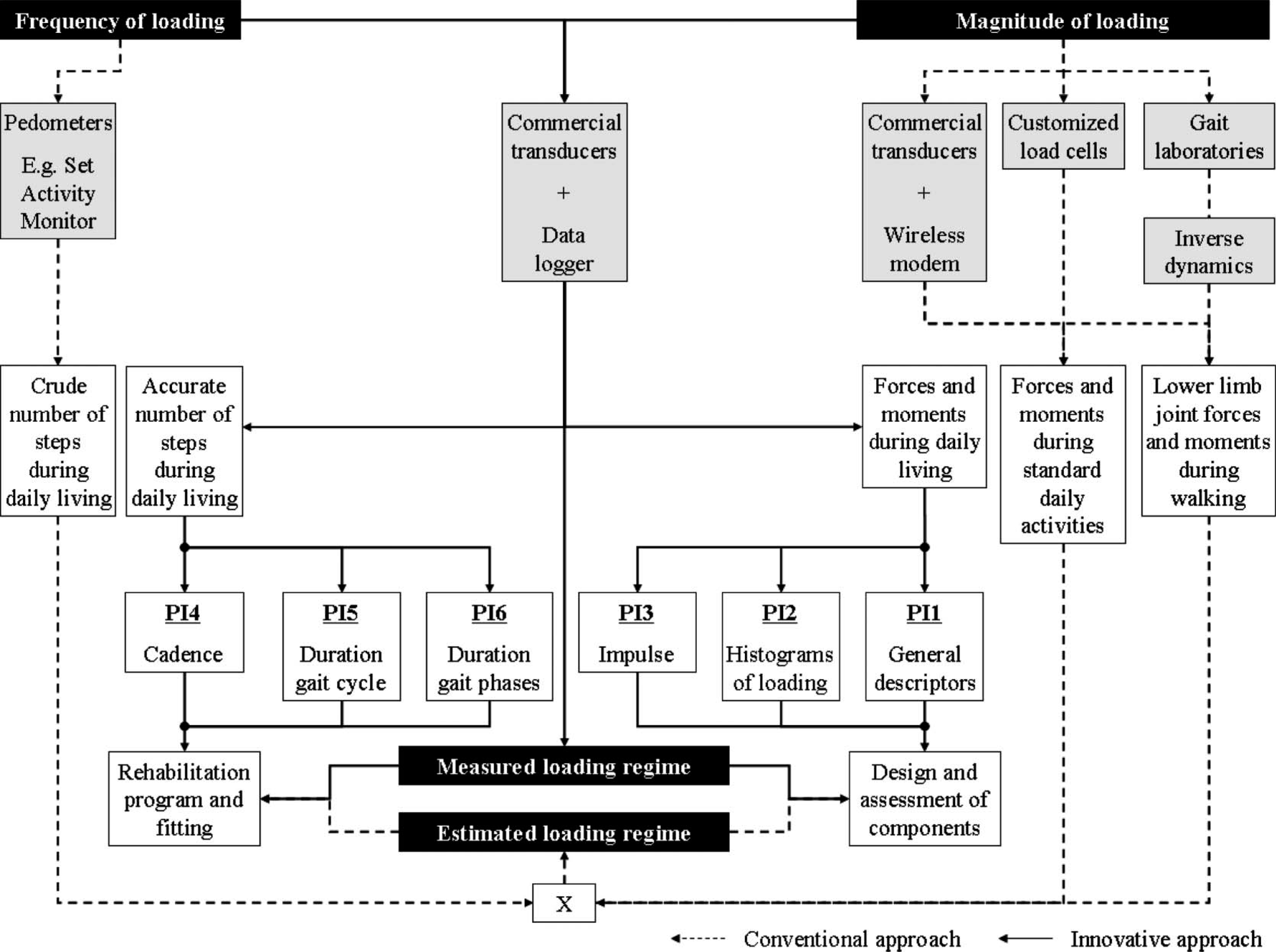
Overview of two approaches for determining the load regime applied on the abutment of trans-femoral amputees. The conventional approach relied on the combination of the measurements of the frequency and magnitude of the loading. The frequency could be measured using pedometers to determine the crude number of gait cycles of the prosthesis during daily living. The magnitude could be measured using a gait laboratory (inverse dynamics equations), customized load cells or commercial transducer during walking in a straight line or standard daily activities. An innovative approach based on a commercial transducer in conjunction with a data logger was used to directly measure the frequency and the magnitude of the load during everyday living environment. This single measurement has the potential to improve the design and assessment of prosthetic components as well as the monitoring of the rehabilitation programme, fitting and usage of the prosthesis through six performance indicators (PI) that can be used in an evidence-based practice.
The frequency of the loading was assessed using pedometers, such as the Set Activity Monitor developed by Coleman et al. (1999). This device was attached to the prosthetic foot and used for continuous recording of step counts per unit time as the individual went about normal daily life. While pedometers provided a representation of the overall usage of a prosthetic leg, they were not able to detect irregular and indistinct gait cycles (Saris and Binkhorst 1977).
The magnitude of the loading was calculated using inverse dynamics, relying on the motion of the prosthesis captured by a motion analysis system and the ground reaction forces measured by a force plate (DiAngelo et al. 1989; Stephenson and Seedhom 2002). The drawbacks of this method are that only one or two steps of walking are usually measured, force-plate targeting can produce altered gait (Wearing et al. 2001), accurate determination of inertia of limb segments are needed, and errors are compounded when involving more than one joint above the ankle. Therefore, the load calculated under these controlled conditions only partially reflected the true loading during daily living. In addition, it is expected that other daily activities that are difficult to assess in gait laboratory settings could produce larger forces and moments than walking (Legro et al. 2001).
This has resulted in the development of a direct method of measurement based on load sensor mounted within the prosthesis (Berme et al. 1975; Sanders et al. 1995; Sanders et al. 1997; Nietert et al. 1998). As pointed out by Sanders et al. (1997) ‘a portable data acquisition and processing system would enhance the utility and versatility of the device’. Consequently, Frossard et al. (2003) presented a recording system based on a commercial transducer and a wireless modem for a direct measurement of the load applied on the socket or the fixation system of trans-femoral amputees. These preliminary studies demonstrated that such apparatus provided reliable and realistic measurements of common daily activities (for example, walking in a straight line or around a circle and ascending and descending stairs and slopes). However, only the most common activities that can be conducted in experimental conditions were included because of the limited range of the wireless connection (700 m).
Recent developments in data recording equipment allowed the transducer introduced by Frossard et al. (2003) to be connected to a data logger. The use of these two devices together enabled the continuous recording of the frequency and magnitude of tri-axial loading during normal daily life.
This study provides a description of the continuous recording of the true load regime
experienced by the fixation of a trans-femoral amputee fitted with an osseointegrated
fixation system during daily activities. The specific objectives of this article are to
present: An apparatus and a procedure allowing this continuous recording. An example of the raw data and six performance indicators (PI) of the usage of the
prosthesis obtained with this method.
Methods
Participant
One male trans-femoral amputee fitted with an osseointegrated fixation participated in this study (age: 33 years, mass: 85 kg, height: 1.70 m). This subject was selected because he was particularly active and presented good functional outcomes following the implantation of the abutment, which was performed three years prior to this study.
This study received the Queensland University of Technology's human research ethics approval. The entire procedure was explained to the subject at which point he read and signed the informed consent form to participate in the study.
Apparatus
The apparatus included a prosthetic leg equipped with a Rotasafe, a transducer, the amputee's current knee and foot, and a data logger (Figure 2). No cosmetic foam was used during recording.
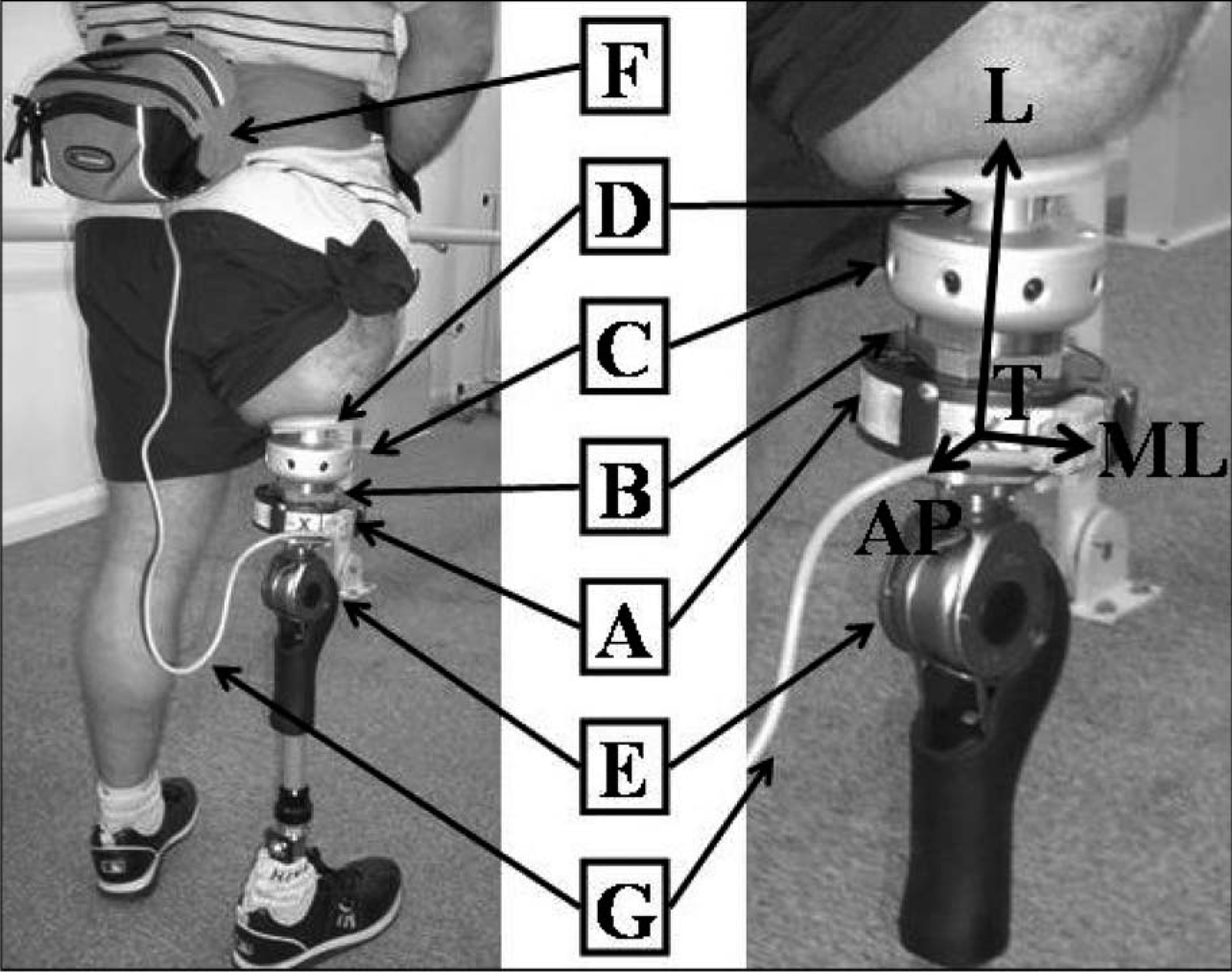
Monitoring of the load applied to the osseointegrated fixation of a trans-femoral amputee and the coordinate system of the transducer T (AP, ML, L). The transducer (A) was mounted to designed adaptors (B) that were positioned between the Rotasafe (C) and the abutment (D). The knee mechanism (E) was connected to the adaptors to enable regular alignment with the local anatomical axes. The transducer was then connected to the data logger (F) by serial cable (G) and attached to the subject via a waist pack (F).
Rotasafe
This protective device commonly worn by amputees fitted with a fixation is based on a safety clutch or ratchet. It is triggered when the torsional load on the long axis of the femur exceeds a set-up threshold in order to prevent excessive torque on the abutment. This device was connected to the abutment and the transducer.
Transducer
The forces and moments were directly measured by a six-channel transducer (Model 45E15A; JR3 Inc, Woodland, CA, USA), similar to the one used in a previous study by Frossard et al. (2003). The power was supplied by a customized battery pack placed in a waist pack attached to the subject. Data was processed using a calibration matrix to eliminate cross-talk between axial sensors. A preliminary experiment demonstrated that forces and moments along the three axes were measured by the transducer with an error of less than ±1 N and ±1 Nm. The transducer was mounted to customized plates that were positioned between the Rotasafe and the knee. These plates were used to anchor the transducer to pyramidal adaptors. The transducer was aligned with the abutment so that the coordinate system was co-axial with the anteroposterior, mediolateral and long axis of the abutment. The alignment of the axes is depicted in the insert of Figure 2. The positioning of the transducer depended on the fixation arrangement of the customized plates. This arrangement allowed only approximate alignment in the transverse plane with the anatomical coordinates of the abutment. A measurement of the angle between the mediolateral axis of the transducer and the abutment was made to allow for correction. The positive value on each axis corresponded to a load applied in compression as well as on the anterior and medial directions by the action force above the transducer.
Knee and foot
The prosthesis included the amputee's current knee (Otto-Bock 3R80) and foot (Otto-Bock 1D10). The subject walked with hard running shoes.
Data logger
The data logger was connected to the transducer by a serial cable and placed in the waist pack. The output of the transducer was digitally stored using an 8-bit data logger (Valitec AD128, Daytona, Ohio, USA) via additional interface circuitry. The 8-bit resolution of the data logger corresponds to a measurement resolution of approximately 8.95 N for the force along the long axis, 4.75 N for forces along the anteroposterior and mediolateral axes, 0.25 Nm for the moment about the long axis and 0.785 Nm for moments about the anteroposterior and mediolateral axes. The forces and moments were recorded with a sampling frequency of 10 Hz allowing a continuous monitoring period of five hours corresponding to 175,600 samples per channel, given the 2 Mb memory limitation of the data logger.
Data collection
The monitoring of the load regime included pre-recording, recording and post-recording phases.
Pre-recording
The amputee was asked to come to the prosthetics department. First, he was briefed on issues of safety and the limitations implied by the attachment of the data logger and serial cable of the recording system (i.e., do not disconnect the cable, being aware of loose cable, etc). The subject was asked to carry on his day as normally as possible since the study aimed to measure the true loading during normal daily living. Then, the prosthesis including the transducer was assembled by a qualified prosthetist and fitted to the amputee. The prosthetist attempted to align the leg as closely as possible to the usual alignment. The prosthetic leg was worn approximately 15 min before recording to ensure subject confidence and comfort.
Recording
The recording started shortly after 1.30 pm, just before the subject left the premises, and lasted until 6.30 pm, giving a total recording time of 5 h. The recording reflected the load regime during a recreational afternoon rather than a work day. The testing took place in January with an ambient temperature of approximately 17°C and overcast conditions, allowing the subject to carry on normal indoor and outdoor activities. No walking aid was used during the recording.
Post-recording
The participant returned the following morning and measurement of the angle for re-alignment of the coordinate system of the transducer was taken. The transducer was then removed. The amputee reported no problems wearing the apparatus but that the waist pack was cumbersome in some instances (e.g., driving a vehicle). No incident related to the recording or any other matters were reported and in fact, the subject reported that his afternoon was typical of his regular recreational day.
Data reduction
The raw force and moment data generated by the transducer were imported into a customized Matlab software program (Math Works, Inc). Raw data was pre-processed and analysed using the following steps:
Step 1: Calibration
Raw force and moment data were calibrated using a specific recording of the initial, unloaded conditions to remove any offset in the data and a transducer specific calibration matrix to eliminate sensor cross-talk.
Step 2: Alignment of coordinate systems
The coordinate system of the transducer and the local anatomical axes of the abutment were re-aligned using a simple rotational transform so that the forces and moments measured reflected the actual load applied on the anatomical axes of the abutment.
Step 3: Overall analysis
Periods of activity and inactivity were determined based on the magnitude of the signal. General descriptors of the loading on the three axes were then calculated, including: minimum, maximum and range (PI 1), load versus duration histograms (PI 2) and impulse values (PI 3).
Step 4: Temporal parameters
Automatic detection of each gait cycle of the prosthetic leg was determined using a standard gait template with a zero-crossing trigger. The cadence (PI 4) as well as the duration of each gait cycle (PI 5) and gait phases, including swing and support phases (PI 6) were subsequently calculated.
Results
Raw data
The raw force data applied on the long axis of the abutment is presented in Figure 3. The overall load profile presented alternate periods of variable length of inactivity (i.e., between 5.30 pm and 6.15 pm) and activity (i.e., between 3.45 pm and 4.30 pm), representing 64% and 36% of the recording time, respectively. The periods of activity included the relatively stationary behaviour seen at 2.20 pm and the ambulation at 4.30 pm.
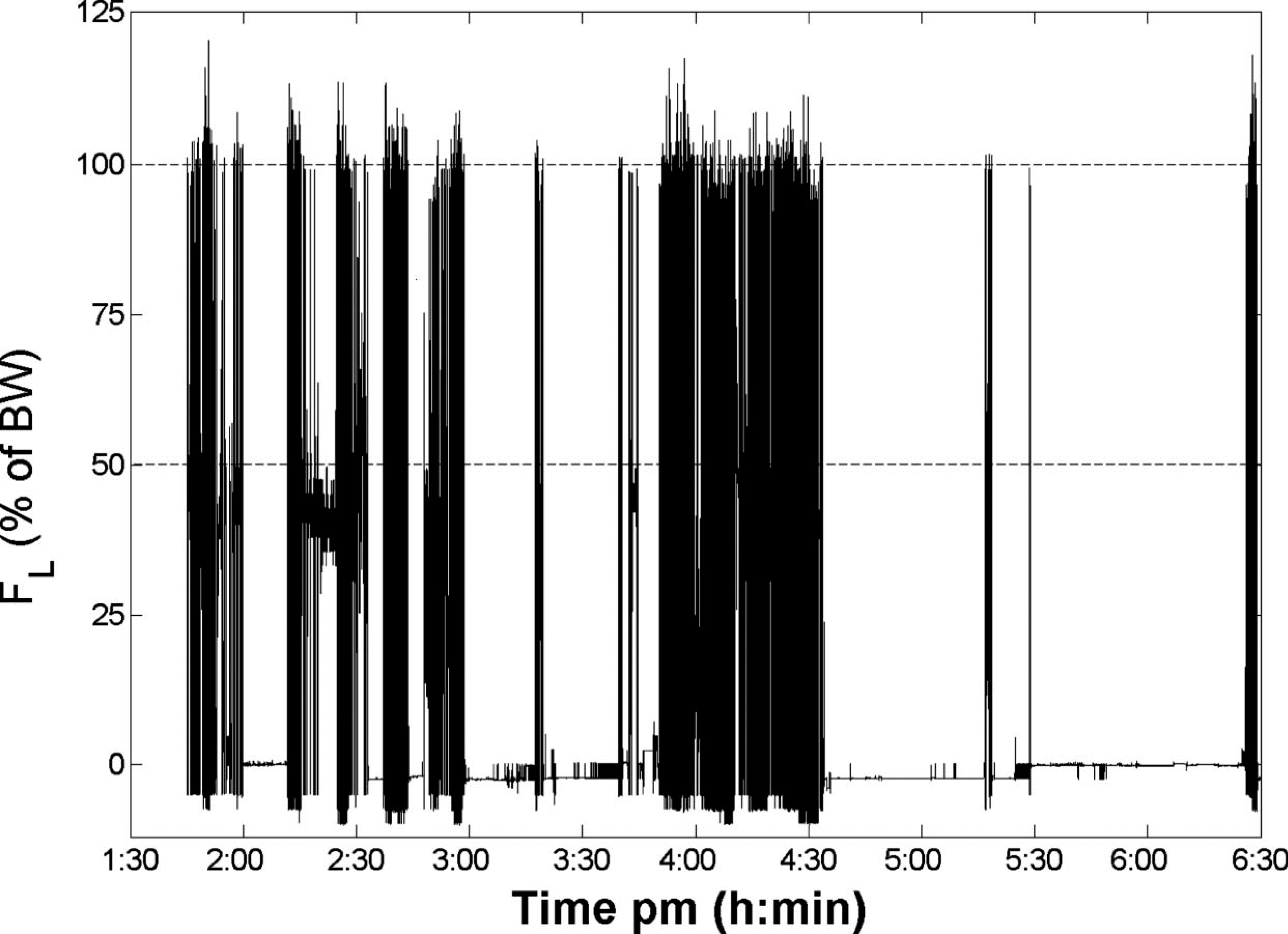
Raw data of force (expressed in percentage of the body weight) applied on the long axis of the abutment of the osseointegrated fixation during approximately 5 hours of recording (from 1.30 pm until 6.30 pm).
Derived information
Various pieces of information of particular interest to clinicians and engineers were derived from the raw forces and moments as presented as Performance Indicators (PI) in Figure 1.
General descriptors (Performance indicator 1)
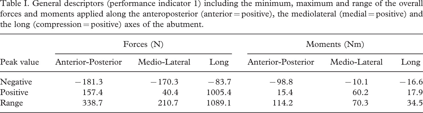
The load parameters of note, such as minimum, maximum and range of the overall forces and moments applied along the three axes of the abutment are provided in Table I. The minimum load applied on the long axis was negative (traction) during the swing phase due to gravity and inertia forces acting on the prosthetic components mounted below the transducer. The maximum load applied on the mediolateral, anteroposterior and the long axes represented 21%, 21% and 120% of the body weight, respectively.
General descriptors (performance indicator 1) including the minimum, maximum and range of the overall forces and moments applied along the anteroposterior (anterior = positive), the mediolateral (medial = positive) and the long (compression = positive) axes of the abutment
Distribution of loading (Performance indicator 2)
The load histograms of the three forces and moments in percentage of the full duration of recording are presented in Figure 4. These histograms outline the amount of time a specific load band was applied on the osseointegration fixation. The force on the long axis of the abutment corresponding to the body weight was applied for approximately 12% of the recording time.
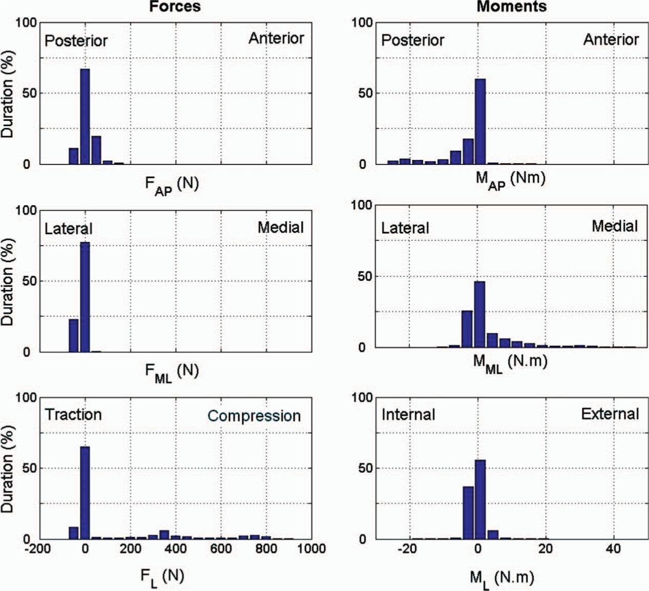
The load distribution of the three forces and moments in percentage of the full duration of recording (Performance indicator 2). The band width for the forces and moments were 47.5 N and 3.5 Nm respectively. (AP = Anteroposterior, ML = Mediolateral, L = Long axis).
Impulse (Performance indicator 3)
This parameter is based on the magnitude and the duration of the force applied during the recording. The norm of the impulse and its component on the anteroposterior, mediolateral and long axis were 2468 kN.s, 395 kN.s, 359 kN.s and 2323 kN.s, respectively.
Temporal parameters during walking (Performance indicators 4 to 6)
The amputee generated a total of 2312 gait cycles of the prosthetic leg during the recording period, giving an approximate overall cadence (PI 4) of 8 stride/min. The duration of the gait cycle (PI 5) was 1.26 ± 0.16 s. The duration of the swing and support phases (PI 6) were 0.58 ± 0.12 s and 0.67 ± 0.09 s, corresponding to 46% and 54% of the gait cycle, respectively.
Discussion
Improvement on current load monitoring techniques
The on-board recording system presented in this paper overcomes many of the limitations of the current load monitoring techniques that rely on a gait laboratory, transducer with wireless modem and a pedometer. Occasional inconvenience due to the waist pack was reported (e.g., while driving a vehicle). However, the portable, light and small 6-degree of freedom transducer and data logger enabled the amputee to ambulate freely in his actual everyday environment. This apparatus allowed direct and continuous recording of the forces and moments, providing a more accurate and realistic description of the loading profile.
Conclusions
This study is the first attempt to present a new on-board recording system based on a commercial transducer and a data logger that permits the continuous recording of the load regime applied on the residuum of trans-femoral amputees during daily living. An example of the outcome was provided for one trans-femoral amputee fitted with an osseointegrated fixation to illustrate the capacities of this new apparatus. In addition, a set of performance indicators that can be derived from these forces and moments is proposed. This work is a milestone in development of future affordable, on-board and user-friendly kinetic recording systems.
This work can be used by multi-disciplinary teams facing the challenge of restoring the locomotion of trans-femoral amputees fitted with conventional and osseointegrated prostheses in the framework of an evidence-based practice.
Footnotes
Acknowledgements
The authors wish to acknowledge the members of the Queensland University of Technology, Prof Mark Pearcy and Prof John Evans as well as Dr Scott Wearing and Dr Winson Lee for their valuable contribution and feedback during the writing of this manuscript. Dr Tim Barker, Bianca Mulder, Mark Hayne, Greg Tevelen and Kim Waddington are also thanked for their technical assistance.
This study was partially funded by the ARC Discovery Project (DP0345667), ARC Linkage Grant (LP0455481), QUT Strategic Link with Industry grant and an IHBI Advanced Diagnosis in Medical Device Grant.