
Abstract
The adapters of modular prostheses are the structural components mostly likely to fail during the use of prostheses because of the high forces and moments occurring during the human gait. In this study, structural performance of a modular uniaxial leg adapter during gait is analysed utilizing computer software. By analysing the results, the relevant product was redesigned in order to prevent possible failures. Subsequently, the developed modular uniaxial leg adapter was tested in accordance with ISO 10328 in order to ensure the safety of the design. Further, the test results are compared with a finite element analysis to evaluate the performance of the numerical analysis.
Introduction
Nowadays, there is a continual development in prosthetic leg components. Modular adapters, which are the main load carrying part of the prosthetic leg, have been investigated widely since they are subjected to high loads and moments created during walking. Researchers at Monash University, Australia, reported the problems defined by patients who have prostheses and by the manufacturers (Monash Rehabilitation Technology Research Unit [MRTRU]2000, Australia). Failed components are grouped and plotted as functions of component types, failure percentage, failure types and patient body weight range, and the distribution of failed lower limb prosthetic components is shown in Figure 1.
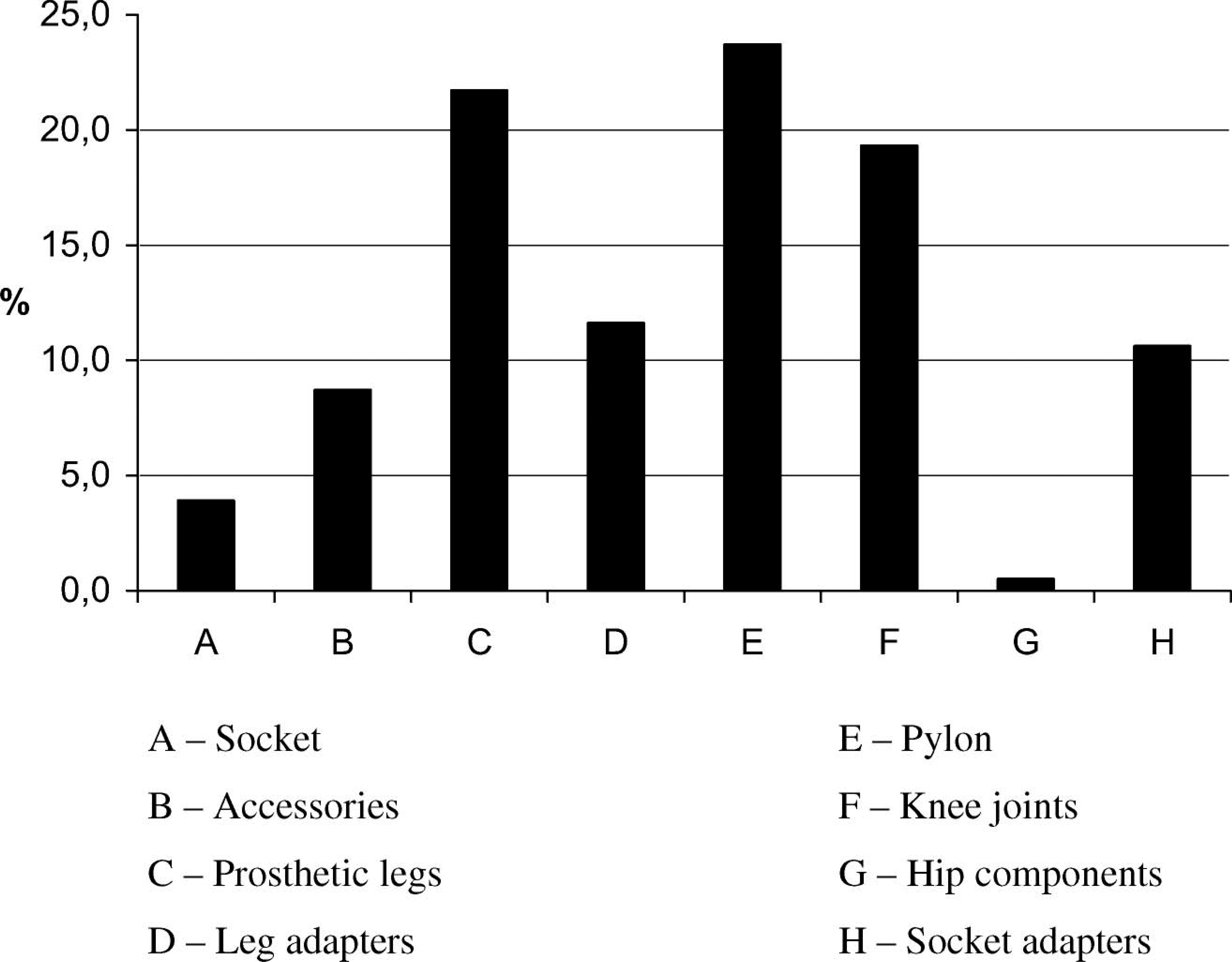
Failure distribution by product type (MRTRU 2000).
As can be seen, the pylon component of trans-tibial prosthesis has the highest fracture ratio of 23.7%. A diverse pattern has been observed in the relation between failure ratio and the prosthesis life. The highest failure rate (34%) is reported as the first month of the product operation (MRTRU 2000).
Generally, there are five main factors that cause component failure with fatigue (60%) being the main reason. Researchers of Monash University reported that trans-tibial components fail functionally and structurally (MRTRU 2000).
The other component failure factors are poor design, misassembled components, misuse or a combination of these factors. Poor design can be recognized after a number of reported cases some years after the product was marketed. In other cases, the product may be used with inappropriate parts and accessories. Assembly and misuse problems can be listed as loose screws, damage of the trans-tibial pylon during assembly (i.e., screw torque) and misuse of the component application as described in the user's manual.
The failure of prosthetic limb components versus weight of the patients was reported by MRTRU (2000) which found that the weight of the patient is not an important factor in the failure of prosthetic components.
Brown and Stewart (2001) investigated fatigue strength of modular pylon adapters made of stainless steel and titanium. They also analysed the failure time of the component related to the patients' activity level with using the finite element method (FEM) and compared their results with the experimental data.
Seewald (1996) examined the motion of the human ankle during gait to develop an ankle-leg system, which can supply the functions of an ankle, in order to improve ankle-leg prosthetic devices that have being used.
There are a number of finite element analyses (FEA) in literature concerning performance of trans-tibial prosthesis (Lin et al. 2004; Zachariah and Sanders 2000) as well as a few clinical investigations of the newly developed prostheses (Zhang et al. 1998; Sanders et al. 2000). In recent years, high-performance advanced composite materials are used in the manufacturing of the prosthesis (Hahl et al. 2000).
The International Standards Organization (ISO) 10328 (1996) defines structural test procedure of lower limb prosthetic components. While ISO 13405-1 (1996) contains the prosthesis classifications and definitions, ISO 13405-2 (1996) gives the definitions of lower limb prosthetic components and defines some standards related to them. EN 12523 (1998) explains the conditions and test methods that external prostheses and ortheses should satisfy.
As a conclusion, it is obvious that a modular leg adapter has great potential to improve the quality of life of patients and bring the lifestyle of a healthy person to patients. Since there is no extensive research on the design parameters and mechanical characteristics of the leg adapter, this study focused on this component and its structural characteristics.
Definition and solution of the problem
The product investigated was the “modular uniaxial leg adapter”. It is used as a trans-tibial joint in prosthetics manufacture. ISO 13405-2 (1996) is the international standard which defines the functions of a modular uniaxial leg adapter. There are cases of failure of this component some time after delivery (Muilenburg and Wilson 2003). In this study, the failed components were investigated and some design errors were determined, especially those related to the normal loads acting on the leg adapter during patients' gait which result in component failure. After some investigation of the foot attachment, cracks were observed around the upper part of the component where a bolt-nut type connection is used (Figure 2) (MRTRU 1998).
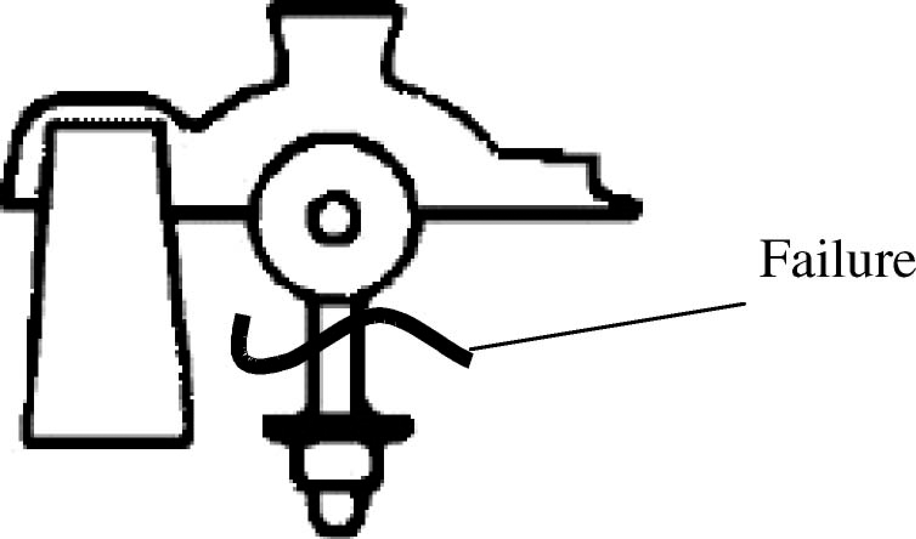
Failure region of the leg component (MRTRU 1998).
In order to solve this problem without affecting the functional properties of the modular uniaxial leg adapter, dimensional modifications of the critical regions and material replacement were considered. The new material should be more appropriate and should have higher strength, better corrosion resistance, and lower specific weight. After these modifications, the new component is compared with the original one in terms of structural performance. The steps of the improvement were as follows:
Under the consideration of the dimensional modifications, a solid model of the adapter was prepared.
The loads that the leg adapter will be subjected to during application were calculated using the ISO 10328 (1996) test standard.
During the gait of a patient, the loads created by the human body were applied to the leg component of the adapter and were analysed by using the FEM to determine the stress and strain distributions in the component.
After considering the stress values in the original component, a new material was selected and some dimensional modifications on the component were made to reduce high stresses by using FEA.
After numerical study, some prototypes of the new component were manufactured and tested considering ISO 10328 (1996) standards.
The experimental results were compared with the FEA.
Modular uniaxial leg adapter
Production of modular prosthetic adapters
Modular prosthetic adapters are weight-bearing components of modular prosthetics. They are assembled in different configurations. Hitherto, geometrical designs of the modular adapter have not varied to any great extent. However, production methods and materials used for adapters have developed rapidly. The aim of this research was to produce adapters possessing the following characteristics:
More strength and fatigue resistance;
Better corrosive resistance;
Less weight;
Limited plastic deformation;
Less production costs.
The geometry and the location of an adapter in modular prosthetic construction determine the production methods for its components. Materials commonly used in production of these components having the required mechanical properties are stainless steel, titanium, and reinforced composites. Because patients mostly demand lighter components the manufacturers choose materials such as titanium and aluminium. The production methods for components of adapters to be produced from metal are casting, machining and forging.
The casting method is preferred for components produced from titanium, aluminium and stainless steel. In order to manufacture the components by casting the adapters have to be located in parts of the prosthetic legs which are not subjected to large forces and moments, and the components must have a geometric structure that can not be produced by other methods. Hence in this study, only the housing of the adapter was manufactured by the casting method.
The machining process is the most common method and by using the CAD-CAM technology high quality components can be produced quickly. It was concluded that the shaft of the adapter will be produced by this method.
In recent years, the forging method has been often used in the production of adapter components because of the need for adapters that have to bear the higher weights of patients nowadays (MRTRU 2000). In the present study, two leg components that are subjected to large forces were manufactured by this method.
Structure of modular uniaxial leg adapter
The modular uniaxial leg adapter is a lower prosthetic component used together with a uniaxial prosthetic foot. The adapter is assembled to the uniaxial foot by two screwed rods with nuts. During assembly, two rubber cushions are placed under the housing element according to the requirements of the patients. A solid model of the adapter investigated in this study was prepared consisting of the following seven components: a housing element, two bars, two washers, a shaft and a bush (Figure 3).
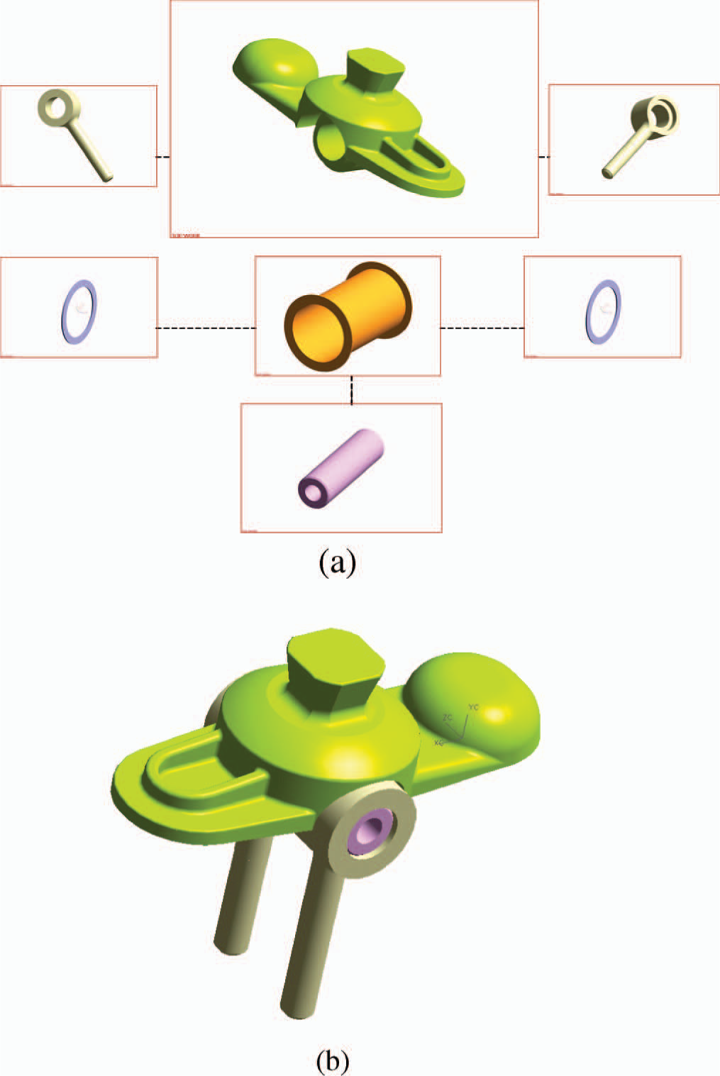
(a) Solid model of the components of the leg adapter; (b) Solid model of the modular uniaxial leg adapter.
Materials used in production of modular uniaxial leg adapter
Components of lower limb prostheses have to satisfy the test criteria of ISO 10328; regarding this standard, the prosthetic components have to be tested for three categories of weight, namely for 60 kg, 80 kg and 100 kg. Furthermore, the standard requires that the tested adapters must be taken from serial production (not from prototypes) and a different sample has to be used for each test.
Analysis of forces acting on the adapter
The human being creates forces and moments in certain parts of the body during gait. Hence, modular leg prosthetics and components, which are attached to a patient, are subjected to static and dynamic loads during walking. The ISO 10328 standard for structural testing of lower limbs determines load acting sequence and maximum values of static and dynamic loads.
In the analysis of the modular uniaxial leg adapter by using the FEM, loading parameters that are given in the ISO 10328-4 (1996) are fundamentally used. According to this standard the loading conditions to be applied are condition I (the instant of maximum loading occurring early in the stance phase of walking) and condition II (the instant of maximum loading occurring late in the stance phase of walking) (ISO 10328-3 1996). These forces and moments are defined as follows:
Axial force Fu : Axial force along the u-axis. Positive Fu compresses the prosthesis in its longitudinal direction.

Twisting moment Mu : Moment about the u-axis. Positive Mu tends to cause an internal rotation of the distal end on the leg relative to the proximal end.

According to ISO 10328-4 (1996), the axial force Fu and twisting moment Mu are calculated by means of Equations 1 and 2, in which uA and uK denote height of the ankle joint from the level of ground and height of the knee joint from the same level, respectively.
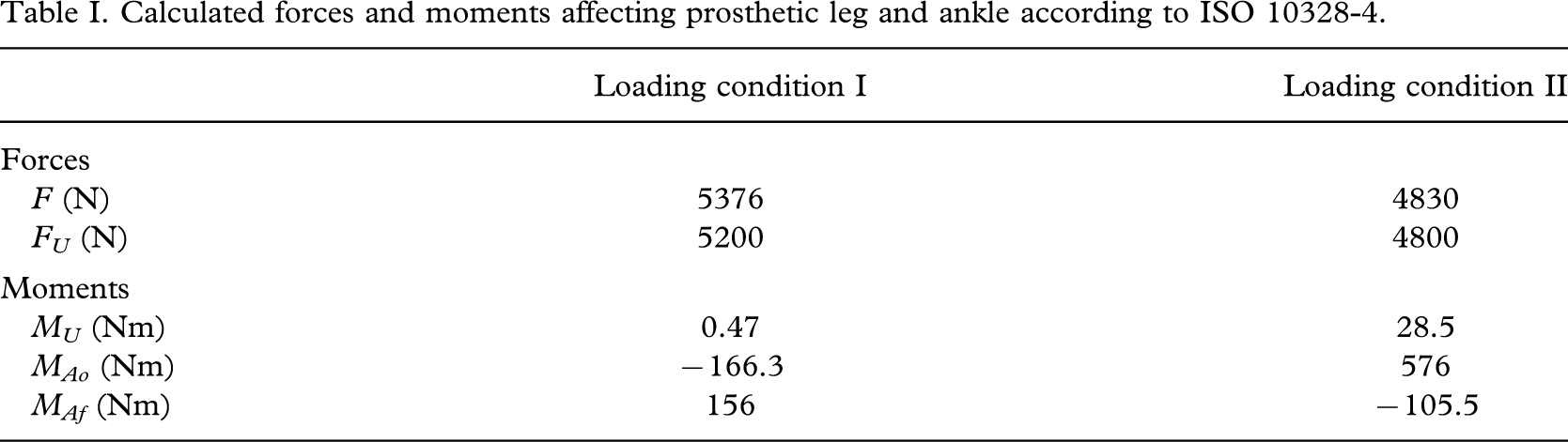
In this study, these forces were calculated according to these formulae. By increasing these values by 20%, the forces acting on the ankle joint of the prosthetics in loading conditions I and II were found. In these calculations, the height of the ankle joint uA from the ground level and the height of the knee joint uK from the same level are taken as uA = 60 mm and uK = 500 mm, respectively. Thus, the maximum test forces for loading conditions I and II acting on product are FI = (1.2) 4480 = 5376 N and FII = (1.2) 4025 = 4830 N, respectively. Table I illustrates the calculated forces and moments acting on the prosthetic leg and ankle in the corresponding cases.
Calculated forces and moments affecting prosthetic leg and ankle according to ISO 10328-4.
Analysis and development of the adapter
Analysis of the adapter by using the FEM
The housing and the bars of the adapter are the basic load bearing elements. Therefore, only these components are analysed with FEM.
In the examination and improvement of the modular uniaxial leg adapter, the material studied was stainless steel AISI 420 which is the material that has been found to fail frequently.
The solid model of the leg component (bar) was created by “Unigraphics” and it was meshed with the finite elements of “Tetra 4”. This element enabled more intensive meshing and faster analysis. The strength analysis followed the criteria of Von-Misés. The possible fracture sites of the leg of the adapter were more finely meshed in order to improve the accuracy of the analysis.
The housing and leg components function inside of an elastic material (prosthetic foot). Hence, real force values acting on the product decrease. However, forces determined according to ISO 10328-4 (1996) were applied directly to the components in the analysis that the adapter was subjected to higher loading. Thus, the product design has a large safety factor.
The FEA carried out in this study for improving the product consist of the following four steps:
Modelling and analysis of the failed adapter made of stainless steel AISI 420.
Selection of an appropriate material for a “new” adapter to be produced.
Analysis of the “new” leg component to be produced and comparison with the original one, and if it is necessary, modification of the new component dimensions.
Discussion of analysis results of the “new” design.
Determination of boundary conditions
Free-body diagrams of the leg component for loading conditions I and II. For the leg component, two boundary conditions were determined. The first condition is the bearing of the leg, which joins the leg to the housing component with shaft (Figure 3). The second is the upper part of the helix of the leg, where the leg is attached to the modular uniaxial foot (Figure 4). Figure 5 illustrates the mesh of the leg and housing components.
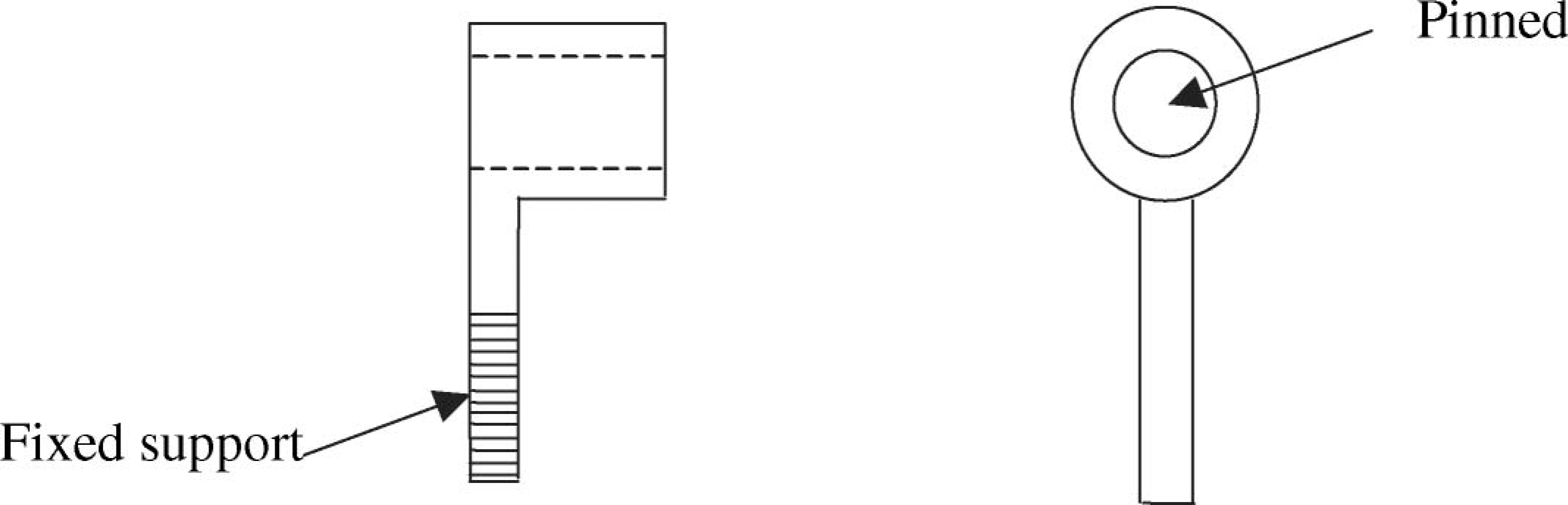
Boundary conditions of the leg component (bar).
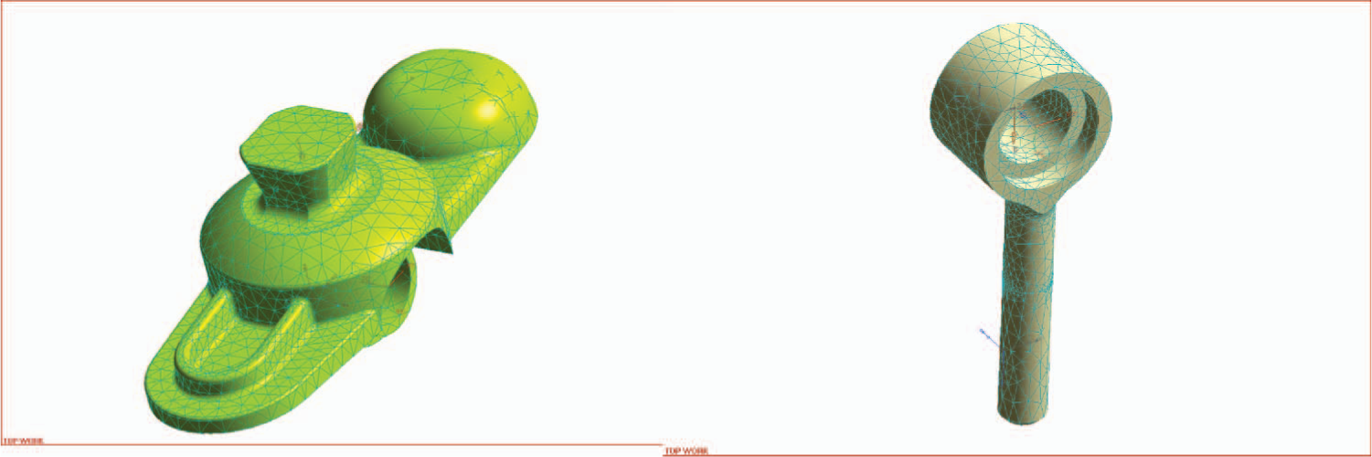
Mesh of the leg and housing components.
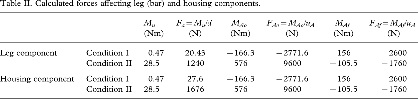
Table II illustrates how moments acting in the plane of ankle are transferred to the leg component according to ISO 10328-4 (1996). In calculations, the height of ankle plane from the level of ground uA is taken as 60 mm and the distance between axes of the legs is d = 23 mm. Figure 6 shows the effective directions of the calculated forces on leg components.
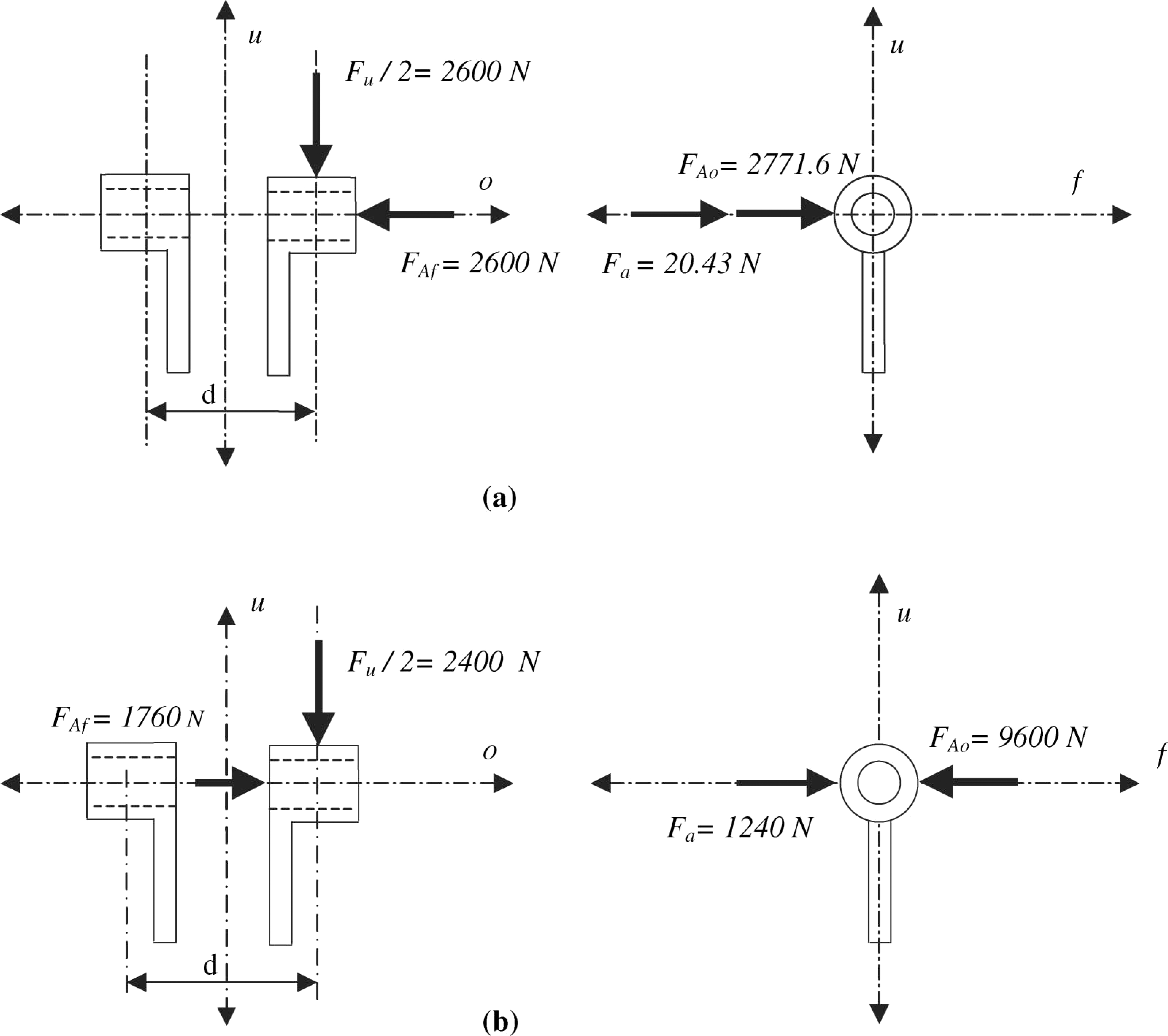
(a) Free-body diagram of the leg component for loading condition I; (b) Free-body diagram of the leg component for loading condition II.
Calculated forces affecting leg (bar) and housing components.
Free-body diagrams of the housing for loading conditions I and II
The housing of the adapter is connected to the leg component with a shaft. This element has only a bearing of the shaft as a constraint. Thus, the first boundary condition for the housing in FEA is to be applied so that it can rotate on the shaft. It is considered that the second boundary condition is to be determined separately for loading conditions I and II, in which maximum forces and moments occur during gait according to ISO 10328. So, this boundary condition is applied to the rear and the front regions of the housing for loading conditions I and II, respectively (Figure 7).
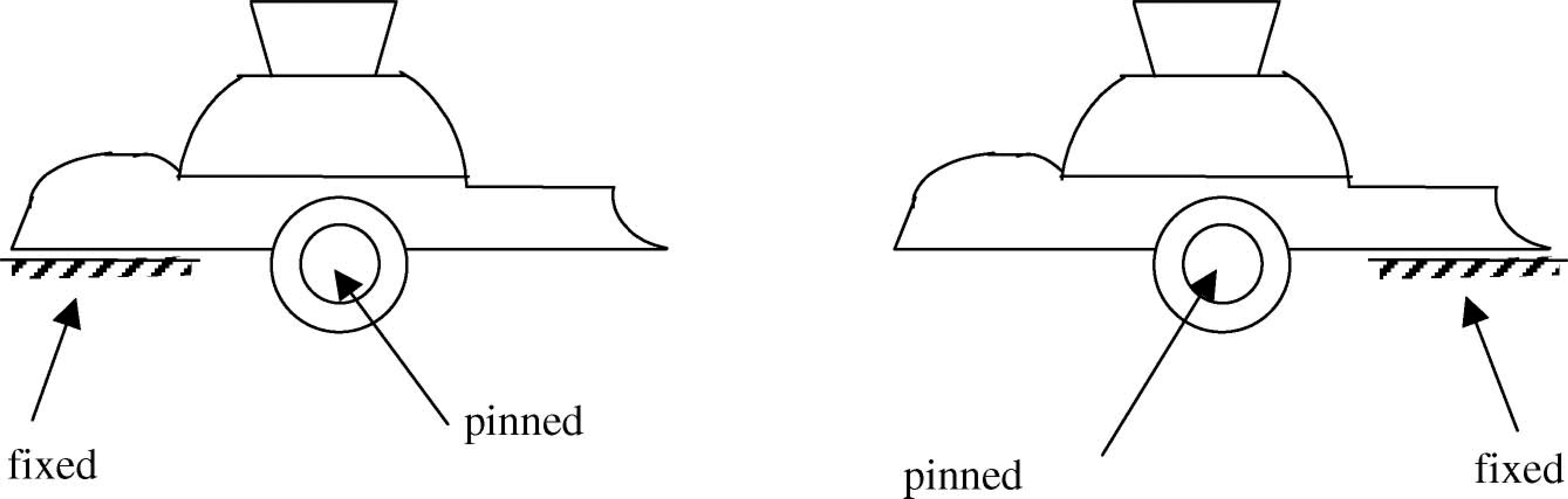
Boundary conditions of the housing in loading conditions I and II (left and right).
Table II also shows, how moments acting in the plane of ankle are calculated for the housing component according to ISO 10328-4 (1996). In calculations, uA = 60 mm denotes the distance between the ankle plane and the ground, and the outer edge of housing pyramid is taken as a = 17 mm. Figure 8 demonstrates the lines of actions of the calculated forces on housing component.
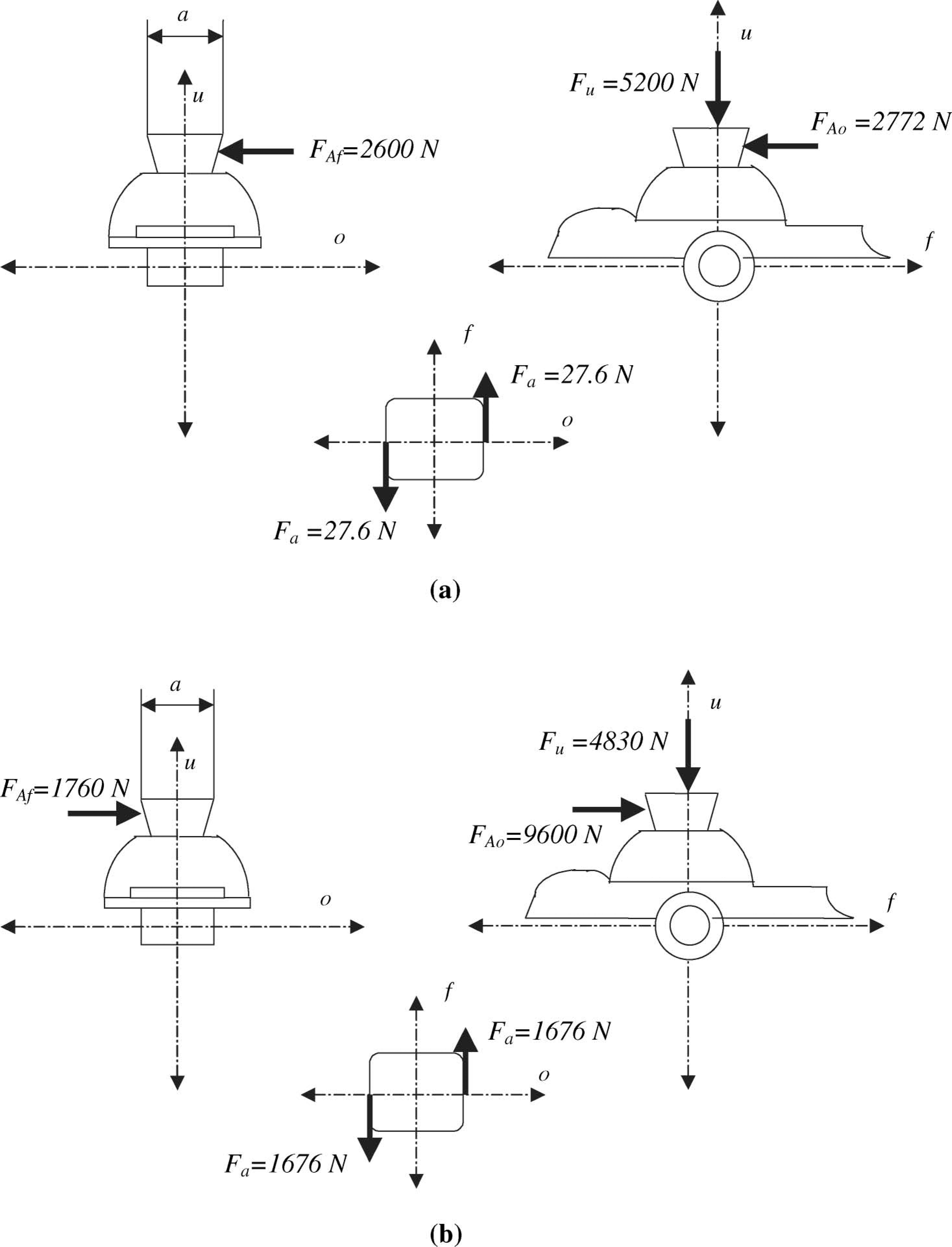
(a) Free-body diagram of the housing component in loading condition I: front view; lateral view; top view of pyramid. (b) Free-body diagram of the housing component in loading condition II: front view; lateral view; top view of pyramid.
Improvement of the adapter
Analysis of the original leg component
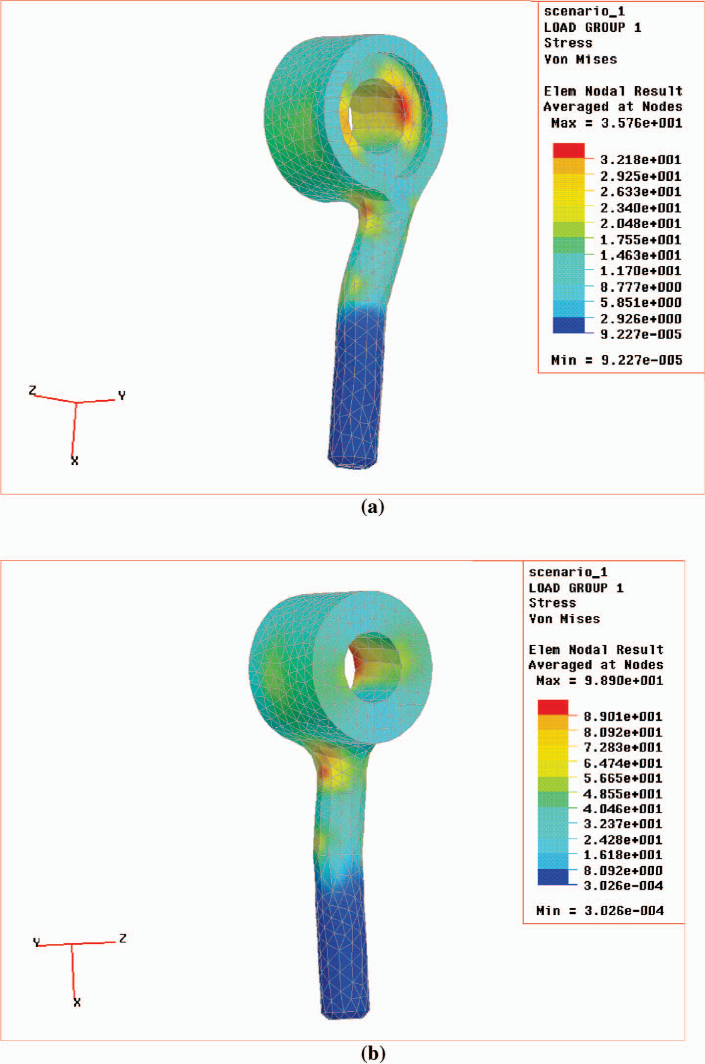
The leg component produced from stainless steel AISI420 was analysed for both loading cases by using the FEM. As shown in Figure 9a, large stress values are obtained in the upper part of the leg, especially in the area which is connected to the circular hollow head region in condition I. It results due to the small radius of curvature. In this location, stress concentration occurs with a maximum value of 464 MPa in comparison to the other parts of the leg component, in which stress values range between 230 MPa and 380 MPa. In loading condition II, very large stress values are obtained in the area, where the rod connects to the head with a small radius of curvature (Figure 9b). These stresses have a maximum of 1044 MPa, and range between 850 and 930 MPa and are distributed over a large surface.
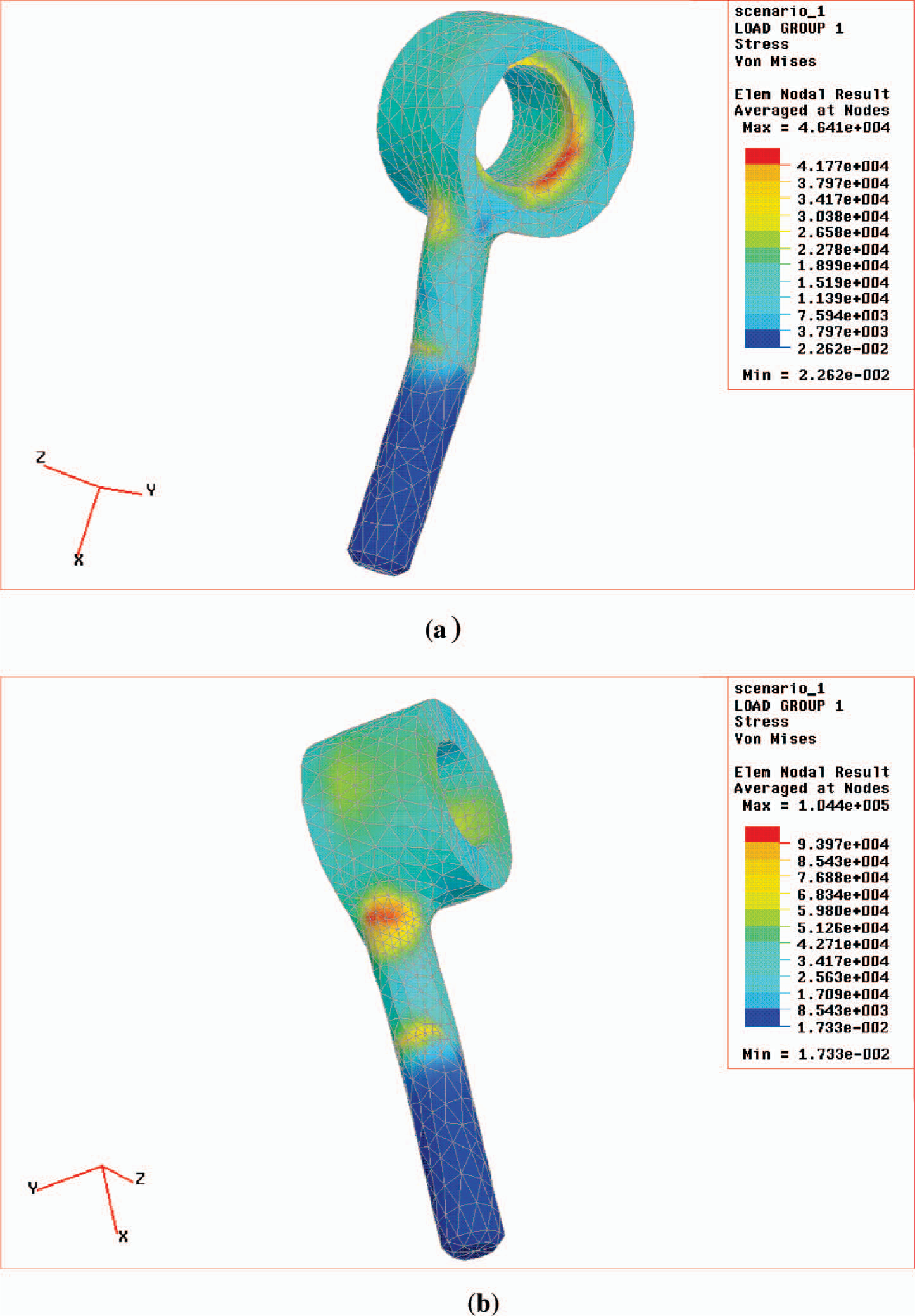
(a) Results of analysis of the original leg component in loading condition I (inner view); (b) Results of analysis of the original leg component in loading condition II (outer view).
Determination of an appropriate material
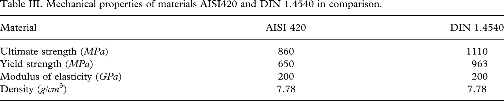
In order to improve the mechanical properties of the leg component, a new material was investigated. This material should have better mechanical properties and must comply with functionality of the leg component as follows: more strength and fatigue resistance, more corrosive resistance, less weight, less production cost, and limited amount of plastic deformation. The investigation resulted in the material DIN 1.4540 being selected regarding the criteria given above. Table III shows the mechanical properties of the materials AISI420 and DIN 1.4540 for comparison (www.matweb.com).
Mechanical properties of materials AISI420 and DIN 1.4540 in comparison.
Development and analysis of the “new” leg component
Using the results obtained from analysing the original component the dimensions of the parts in which great stresses occur were modified to strengthen them without affecting the functionality of the component; the radius of the bearing and radius of fillet between the leg and the bearing were systematically changed without significant increase in the weight of the element and without decreasing its functionality. Table IV illustrates the “new” radius of the bearing and the “new” fillet radius of the joint of the leg-bearing.
Modified measurements of the leg component (bar).
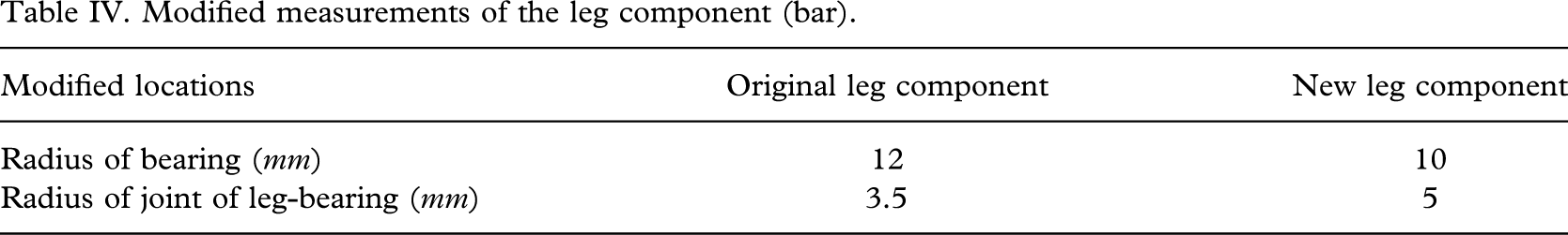
Figure 10a shows the results of analysis that was carried out in loading condition I for the modified leg component. According to the results, the highest stress values arise in the bearing due to its sharp curvature. In this location, the maximum stress value is 357 MPa, and stress values in the other parts of the leg component are determined to be 175 – 290 MPa.
(a) Results of analysis of the new leg component in loading condition I; (b) Results of analysis of the new leg component in loading condition II.
The results of the analysis of the new leg component in loading condition II are given in Figure 10b. Thus, the maximum stress values arise in the bearing and in the joint of the leg-bearing up to 989 MPa. Additionally, stress values in the other regions of the leg component are obtained between 647 and 809 MPa.
Analysis of results
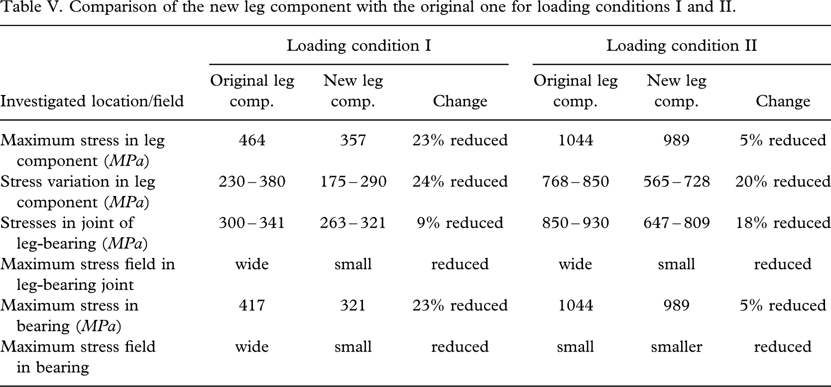
Table V illustrates four different values and two different fields of the original and new leg components in comparison for loading conditions I and II. The results indicate that the maximum stress values decrease between 5 and 24% and that the stress fields shrink likewise. So, the ultimate strength of the new material is not exceeded in spite of aggravated conditions.
Comparison of the new leg component with the original one for loading conditions I and II.
Analysis of the housing
The housing component to be produced from the material of DIN1.4540 was analysed. The results of analysis for loading conditions I and II are given in Figure 11; in both conditions the maximum stress values arise at the bottom of the pyramid of the housing due to stress concentration. These maximum values were found to be 710 and 1063 MPa in loading conditions I and II, respectively. While analysing the housing component, the effect of the rubber cushions that reduce the stresses in rear and front parts of the housing was omitted. It is assumed that the housing is constrained in its rear and front parts, in which forces act directly. The maximum stress values found do not exceed the ultimate strength of the new material selected for production of the housing component. Thus, it is appropriate to mass-produce this component from the new material.
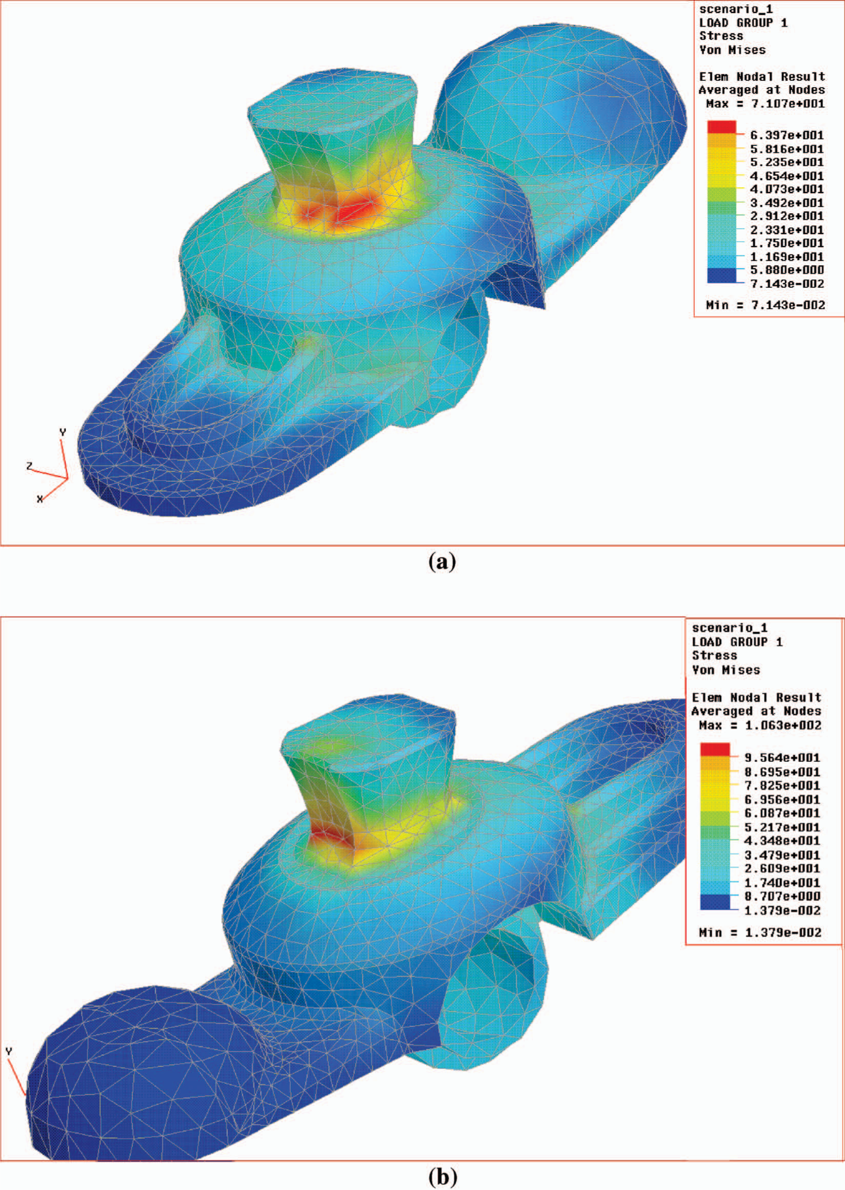
(a) Results of analysis of the new housing in loading condition I; (b) Results of analysis of the new housing in loading condition II.
Testing and results of the new leg
The first section of ISO 10328 outlines the configuration that is necessary for testing the product; its third section gives the structural test procedures to be applied; and its fourth section determines loading parameters and supporting configurations of the product to be tested in the test machine.
Testing of the new leg component
The new leg component was tested according to the criteria outlined in ISO 10328 (1996). In loading conditions I and II, F = 5376 N and F = 4830 N were applied to the leg component, respectively. Figure 12 illustrates the new component before and after the test.
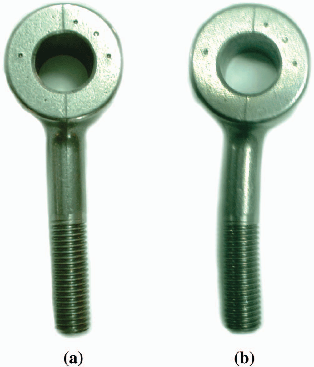
View of the leg component (a) before and (b) after test.
Neither cracks nor fractures were found during inspection of the tested component. Even though the component was deformed plastically in the middle, the deformation remained between limits of ISO 10328. Hence, the product fulfils the criteria of ISO 10328.
Elasto-plastic deformation distribution arisen in the FEA of the new component is shown in Figure 13a, and the maximum deformation found is 1.87 mm.
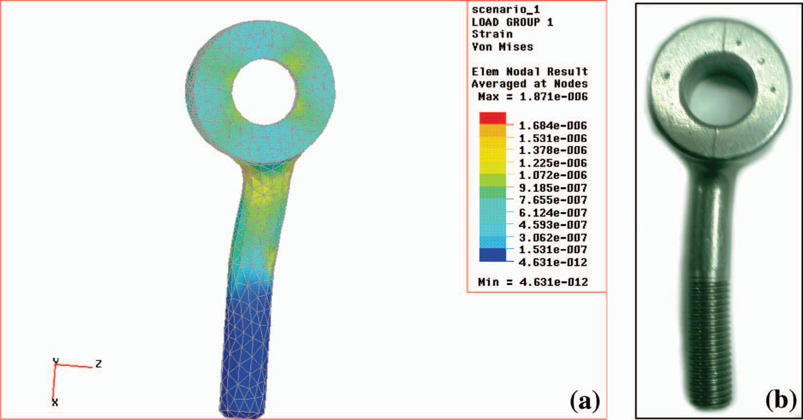
FEA of leg component (a) before production and view of the component (b) after test.
During the test, the maximum moment occurred when loading condition II was applied to the leg component, and the maximum elasto-plastic deformation was found to be 1.8 mm. As the elasto-plastic deformation in the FEA of the leg component is 1.87 mm, both results are in a good agreement (Figure 13a and b). The small difference may result from the fact that the boundary conditions selected for the FEA are less appropriate than the test conditions; the leg component is in an elastic continuum during the test, similar to it being in use, whereas it is analysed in rigid continuum. After the test, the maximum plastic deformation in the component is determined as about 1.7 mm.
Conclusion
In this study, a detailed investigation of the modular uniaxial leg adapter, which showed mechanical failure, has been carried out. Firstly, 3-D models of the leg and body parts of the components were prepared. The loads that the components are subjected to during their usage were applied as the models were transferred into the FEA environment. High stresses were observed at the common failure regions of the leg and housing components under these conditions (Dincel 2003).
Secondly, a material having better mechanical properties (DIN 1.4540) was selected for the components. Some geometrical changes of the critical regions were carried out on the leg component by checking the new construction at each step with the FEM. After these analyses, the stress values at the critical regions in both components were reduced significantly.
Thirdly, the new leg component (bar) is manufactured and tested according to ISO standards. As a result, the leg component satisfied the conditions, which are described in ISO 10328 indicating that both developed components are appropriate for mass-production.