
Abstract
On-chip cryopreservation of biological cells under low-temperature environments has been successfully demonstrated using a microfabricated chip with an incubation microchamber and microfluidic channels. Microheaters are used as both the resistive heating elements and temperature sensors to control the temperature profile of microenvironment under the liquid nitrogen cooling process. A two-step, temperature-controlled, on-chip cryopreservation process is applied for yeast cells, and after the thawing process, 74% cell survival rate has been accomplished. The reference experiment conducted without using the temperature control results in 27% cell survival rate. As such, this technique could have potential applications in on-chip cryopreservation processes, including those for sperm, embryo, or future cryogenic-based, lab-on-a-chip applications.
Introduction
Cryopreservation is a process where living cells, tissues, or large organs are preserved by freezing in low-temperature environment to stop their biological activities. 1 Occasionally, this process happens under natural settings—animals were buried under frozen ice and/or soil in ancient times and discovered in modern age with relatively well-preserved organisms. Artificial cryopreservation, on the other hand, also took place years ago; history recorded that ancient Egyptians used ice for wound treatments. In the late 17th century, freezing and thawing processes were first successfully demonstrated on fishes, and the major improvements were accomplished in the late 1940s by introducing glycerol to help reducing cell damages in the freezing process. 2 Today, cryopreservation of cell suspension and small tissue has been regularly used in biological routines and facilities. The reproduction of various animal species such as bovine, goat, and human 3 based on cryopreservation has been successfully proved and commercialized. The preservation of sperms, eggs, and embryos to help the people with the problem of infertility has grown into a major medical industry. In this and other applications, continuous efforts have been made to improve the survival rate of the cryopreservation process.4, 5 Similar to many other biochemical procedures that have been implemented at the microscale using the microelectromechanical system (MEMS) technologies, on-chip cryopreservation of living cells could help advancing areas in bioMEMS with integrated on-chip systems for low-cost, high-volume parallel processing.6-8
There are two potentially fatal mechanisms during the cryopreservation process, excessive osmosis and intracellular ice damages. 9 Ice formation occurs first in the extracellular aqueous solution during the freezing process and results in high solute concentration surrounding the living cells, which causes the osmosis effect to drive water out of the living cells.
If the cooling rate is too slow, osmosis can remove water from cells excessively, leading to a harmful high electrolyte concentration inside cells. If the cooling rate is too fast, intracellular ice could form and become the recrystallization sites of large ice crystals later during the thawing process and could damage the cell membranes. The ideal cooling rate, where the survival rate of living cells is optimal, is slow enough that the intracellular ice may not form and is rapid enough such that cells are not damaged by highly concentrated solution or excessive shrinkage. This optimal condition is typically determined empirically and varies depending on the particular cell types.
This work presents the approach of using microchambers and microheaters for the local control of temperature and cooling rate to achieve on-chip cryopreservation. The advantages of using MEMS-based cryopreservation system include (1) more uniform temperature distributions in microchamber because of reduced volume and (2) fast and local temperature control via microheaters. 10 These attributes and our experimental findings could serve as the foundations and design guidelines for future cryogenic-based, lab-on-a-chip systems and applications.
In this article, the cryopreservation with liquid nitrogen (LN), which is the protocol for long-term and/or sensitive cell (like embryos) preservation, is used as the basis to test the effectiveness of the microsystem. This process normally requires a well-controlled cooling profile and is sensitive to its cooling conditions.
Design and Fabrication of the Cryopreservation Chip
An MEMS-based, local cryopreservation device is designed as schematically illustrated in Figure 1 to be compatible with potential future integration with other lab-on-a-chip devices. The device consists of a microchamber and fluidic channels made of polydimethylsiloxane (PDMS) and a microheater/ temperature sensor covered with an electrical insulation layer on top of a glass or silicon substrate. The glass substrate is preferred here because it has much smaller thermal conductivity than silicon to prevent heat losses to the environment and is transparent to facilitate the direct observation of cells under an optical microscope. Several heater materials, including silicon, aluminum, and indium tin oxide (ITO), and different structures (attached or suspended) have been fabricated and tested. ITO is preferred for many biological experiments because it combines good electrical conductivity and optical transparency, and the typical composition of ITO is 90% indium oxide (In2O3) and 10% tin oxide (SnO2). We use ITO as the demonstration example throughout most of the article. A double-spiral shape with large line width is chosen as the basic heater design
11
to have more uniform heating profile and temperature distribution inside the microchamber.
12
The heater was also used as a temperature sensor during the experiment with a special configuration to achieve the measurement similar to four-point probe for better resistance measurement accuracy. A small-line width resistor is designed in between the spiral-shape heater, as an auxiliary temperature sensor, to have higher resistance values for the heater materials with low resistivity. The auxiliary sensor can improve the temperature sensitivity under that condition.
Schematic diagram of the on-chip cryopreservation device, including a microchamber, fluidic channels, inlet and outlet ports constructed on PDMS, and microheater with insulation layer on top of a glass substrate. The top PDMS cap and bottom glass substrate are bonded together with the assistance of oxygen plasma to complete the device.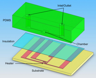
The fabrication process is shown in Figure 2. First, microheater and temperature sensor are fabricated on a Pyrex wafer. The wafer is cleaned, and a layer of 200 nm ITO is sputtered and patterned by a liftoff process. A 200-nm-thick plasma-enhanced chemical vapor deposition (PECVD) SiO2 is deposited and patterned by reactive ion etching afterward for the electrical insulation. Figure 2C illustrates the cross-sectional view after these processes. The PDMS cover cap is fabricated by using a silicon wafer with a patterned, 50-μm-thick SU-8 as the mold insert.
13
PDMS solution is mixed with the curing agent at 10:1 ratio and poured onto the SU-8 mold insert in Figure 2D. After the curing process, PDMS cap is demolded and a 21-gauge flat-tip needle is used to punch through PDMS to create inlet and outlet ports as shown in Figure 2E. The bonding surfaces between the top PDMS piece and the bottom glass chip are treated with 40-s, 40-W oxygen plasma (100 sccm oxygen flow rate), respectively. The two parts are then aligned manually under an optical microscope and bonded together as shown in Figure 2F.
Fabrication process of the on-chip cryopreservation device: (A) ITO heater patterning by the liftoff process; (B) PECVD SiO2 deposition for electrical insulation; (C) contact pads opening by reactive ion etching; (D) molding of PDMS microfluidic system using SU8 mold insert on silicon substrate; (E) inlet/outlet holes constructed by mechanical punching on PDMS pieces; and (F) bonding of two substrates after oxygen plasma treatment and manual alignment.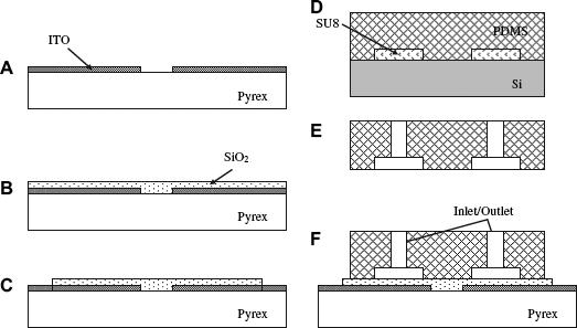
Figure 3A is an optical photo of a fabricated, double-spiral ITO microheater, which is 80 μm in width and 16 mm in total length on top of the glass substrate. It can be seen that there are totally six leads designed to operate the device. Besides the two leads marked as “I,” which will be used to apply current to the double-spiral heater, there are two “V” leads connected very close to the two ends of the heater. The voltage between the two “V” connections and the current going through the heater will be both recorded during the experiment to monitor the heater resistance change as a four-point probe. This resistance change is correlated to the temperature variation inside the microchamber and can be used to realize the temperature control by directing the heating power adjustment. The two auxiliary ports marked as “Aux” are attached to the thin-line resistive temperature sensor fabricated in between the spiral heater. Figure 3B shows the microheater after the PDMS bonding process. The sizes of typical chamber and fluidic channel are 1200 × 1480 × 50 and 80 × 1500 × 50 μm3, respectively. It is noted that the whole chamber is on top of the heater area to effectively use the heating power. Because the thickness of the microchamber is only 50 μm, temperature in the microchamber responds rapidly to the adjustable heating power. Figure 3C shows the final device photo after the PDMS cover is bonded on the device substrate. There are two sets of device on one chip. The electrical wires are bonded to the six leads to connect the signals out, and kapton tapes are applied to assist the positioning of the wires.
Optical photos of (A) the fabricated double-spiral-shape ITO heater with two voltage terminals (V) and two current terminals (I) for heating and temperature sensing, and two auxiliary terminals (Aux) for a complementary temperature sensor; (B) the PDMS cap with microchamber and fluidic channels bonded on top of the microheater; and (C) the overall view of the final device. There are two sets of device on one chip. The electrical wires are bonded to connect the signals out, and kapton tapes are applied to assist the positioning of the wires.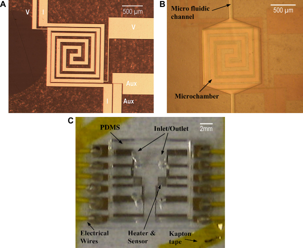
Experimental Results and Discussions
Biocompatibility Tests
It is important to validate that the fabricated on-chip devices are broadly biocompatible to various species. We conduct baseline incubation experiments for the qualifications on four different cell types, including two microorganisms:
Biocompatibility testing results for the on-chip cryopreservation device. (A) Fluorescence photos of 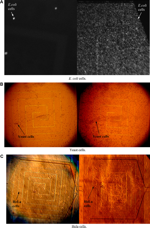
Temperature Calibrations
Because the SiO2 insulation layer between the ITO microheater and the cell solution is only 200 nm thick, the temperature difference between the microheater and the liquid will be negligible. In our experiments, the microheater serves as both the heating element and temperature sensor. The heater temperature derived from the heater resistance change will be used as the sensing signal to control the heating power directly. Figure 5 illustrated the temperature calibration of the heater, conducted under the dry mode (without cell solution) to correlate the heater resistance to its own temperature. A fine-wire thermocouple with tip diameter of 25 μm (CHAL-0005, unsheathe K-type thermocouple from Omega Engineering, Inc., Stamford, CT) is placed on top of the ITO heater area as the reference temperature sensor. The resistance of the ITO heater is recorded with respect to the thermocouple temperature while increasing the heating power of the ITO microheater. The calibration was conducted from —95 to 50 °C, and a good linearity was observed between —60 and 50 °C. The measured temperature coefficient of resistance as the result of the linear fit is 3.35 × 10⁻⁴/°C. The curved tail on the plot at the lower temperature range is typical when the material has impurities or defects. The on-chip temperature was estimated by using this temperature calibration result together with the established theoretical modeling on microheaters.
15
Resistance versus temperature characterizations of the fabricated ITO microheater between —95 and 50 °C.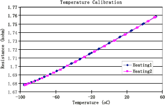
Experimental Setup and Procedure
The experimental procedure of on-chip cryopreservation is illustrated in Figure 6. In general, small biological cells have better survival rate than large cells during the cryopreservation process and are not good candidates for comparative studies. Yeast ( (A) Experiment procedure for on-chip cryopreservation of cells: the cell solution is loaded into the microchamber by a pipette; the device is attached to a metal beam and lowered into LN vapor while the on-chip heater controls the cooling profile; the preserved cells are diluted into the solution with the right ratio; the solution is spread on a agar plate to calculate the survival rate. (B) Experimental setup.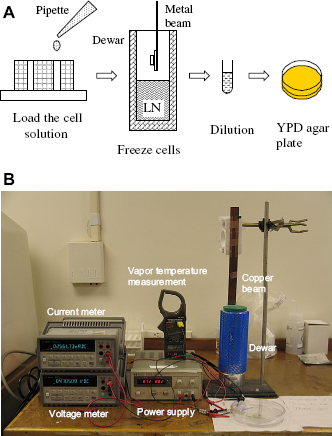
The solution is taken out of the chamber by injecting 20 μL sterilized deionized water into the device 10 times. The collected specimen is then diluted to 1:103 and further to 1:104 and 1:105. The same procedure on a new preservation chip without the heating process was conducted for comparison. Afterward, 50 μL of each sample was spread and cultured on a YPD agar plate in a 30 °C incubator for two days. The survival rate is determined by counting the colonies on the plates.
By diluting the same sample into different dilutions and plating each dilution on identical plates several times, it is found that the highest counting accuracy can be achieved when the grown colonies are between 100 and 150, with an estimated variation to be ±5% within different plates. As the colony number is in the range of 200—300 and 50—100, the estimated variations are ± 10% and ± 15%, respectively. If the colony number is lower than 30, variation rises dramatically because the base number is very small. If the colony number is higher than 400, on the other hand, it is very difficult to count the single colonies.
Results and Discussions
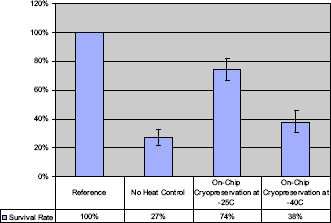
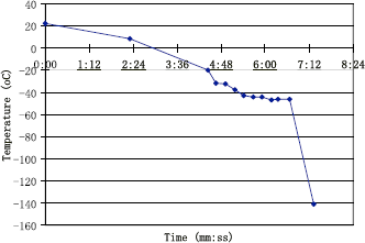
Figure 7 shows an example of the viability results from our initial test: colonies of cells on the agar plates from the samples going through no cryopreservation process (top); direct and rapid cryopreservation with LN without temperature control (left bottom); and on-chip cryopreservation with the two-step temperature control (right bottom). Each white dot on the brown agar is a single colony of cell grown from a viable cell. A yield improvement from no heat control to the on-chip option can be visibly observed. The final survival results from our device are summarized in Figure 8, and the preliminary experiments show that around 74% survival rate is achieved with the two-step, on-chip temperature control process with a holding temperature around —25 °C, while the device plunged directly into LN vapor gets only about 27% survival rate. Another experiment of on-chip cryopreservation test is conducted with a holding temperature at —40 °C for 3 min as illustrated in Figure 9, and the survival rate drops to 38%. This temperature control is completed by an open-loop, manual procedure (each point in Fig. 9 represents an important temperature or control event). It is suspected that some cells in this experiment may have experienced the formation of intracellular ice crystals as the holding temperature is low.
Viability results of on-chip cryopreservation experiments. Each white dot is a cell culture grown from a viable cell. Photos show (top) the results from reference without going through the cryopreservation process, (left bottom) the base line results of cells after direct and fast LN cooling, and (right bottom) the on-chip cryopreservation results with the two-step cooling control as shown. The survival rate results and comparisons of on-chip cryopreservation experiments. The temperature profile for the on-chip cryopreservation experiment using embedded heaters to control the temperature profile to have a temperature holding period around —40 °C for 3 min. Each point is an important temperature or control event.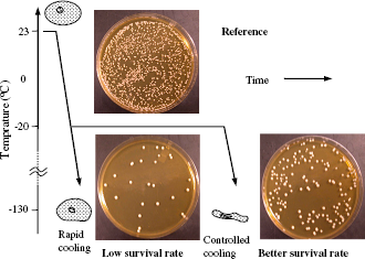
It is clear that the open-loop temperature control is lack of accuracy, and an automatic feedback control system should be able to improve the system performance and the final result. A further optimization of microheater and chamber design might provide better temperature controllability. Beside the controlled cooling process, a controlled thawing process could also help to further improve the survival rate. Although the above experiments were all tested under the LN environment, the system should have no problem to work under other low-temperature environments like refrigerators to provide localized temperature control. During the experiments, it is found that ITO electrodes gradually dissolved in the assays probably because of the poor coverage of insulation layer. Other insulating materials can be studied to replace PECVD oxide. 10
The limited data above serves only for the purpose of proof-of-concept experiments. Reliable control and repeated experiments on the cooling rate, holding temperature and periods on various cell species have to be conducted to establish the best empirical protocols for individual cell types. This will require substantial efforts in future investigations.
CONCLUSION
Proof-of-concept experiments have been conducted for the feasibility study of on-chip cryopreservation using a two-step cooling process. The key experimental outcome, the survival rate of living yeast cells, is evaluated by counting viable cultured cell colonies on agar plates. Results are compared with the control experiment, in which the living cells are directly plunged into LN vapor. It is found that the average survival rate for the control experiment is about 27%, and the survival rates for cells running through the on-chip cryopreservation process with a holding temperature at —25 °C and —40 °C for about 3 min are about 74% and 38%, respectively. Experimental setups, procedures, and biocompatibility of the MEMS-based cryopreservation device with several different cell lines have been established. It is believed that further investigations will increase the survival rate, including the use of feedback control on the microheaters to control the device temperature, comprehensive studies on various cooling profiles and holding temperature with respect to various cell species, and temperature control during the thawing process. As such, this on-chip cryopreservation technique could be potentially applicable as the platform for future cryogenic-based, lab-on-a-chip applications.