
Abstract
ARUP receives on average more than 23,000 specimens/day for laboratory testing. The residual samples are stored in trays with a capacity of 450 tubes at −20 °C for up to a year. Previously, the disposal of these samples required a minimum of 1 full-time equivalent (FTE) for the manual disposal of up to 39,000 samples/day. We report the development of an automated workcell for the disposal of these samples. The workcell has reduced the FTE requirement by sixfold to 0.18 and has minimized potential biohazardous exposures.
Introduction
ARUP laboratories receive on average 4000–40,000 specimens/day for clinical laboratory testing. To accommodate this specimen volume, an extensive automated system for specimen handling has been developed to transport and track specimens through the testing process. 1,2 The automated specimen management group is responsible for storage, retrieval and disposal of the residual specimens. These specimens are stored at −20 °C from two weeks to a year depending on the requirements of the test. To handle these high capacity storage requirements, an automated track system delivers specimens to distribution centers for clinical testing. After analysis, the specimen tubes pass through a sorter that distributes them into trays based on the storage time requirements. The filled trays are then transferred to the −20 °C freezer which can store 2,349,000 specimens, consisting of 5220 stainless steel trays in an indexed shelf system (Fig. 1). 3 Each day, a discard report is generated listing on average 66 trays with expired specimens for disposal. Previously, these trays were processed by hand, requiring manual disposal of 20,000–39,000 specimen tubes/day. This process required a minimum of 1 FTE to complete the task with exposure to biohazardous material and potential repetitive motion injury. We describe the development of an automated workcell which empties all tubes from a tray in a single motion.
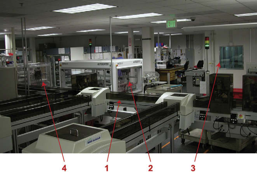
Overview of automated specimen management. Automated specimen management for transport and sorting consisting of the track transport system (1) and storage autosorters (2) for transfer of samples to the 60 × 30 × 26 ft −20 °C freezer (3). Samples are discarded in the tube removal workcell (4).
System Overview
The tube disposal workcell was designed to accommodate a 338 × 670 mm stainless steel tray capable of holding 450 tubes (Fig. 2). These trays are designed to accommodate tubes varying in outer diameter (OD) from 12 to 16 mm by holding and centering them in place with a plastic collet. Most of the specimens received arrive in a standardized 15 × 92-mm false bottom transport tube. However, “vacutainer” and other tube types ranging in heights 75–100 mm are present.
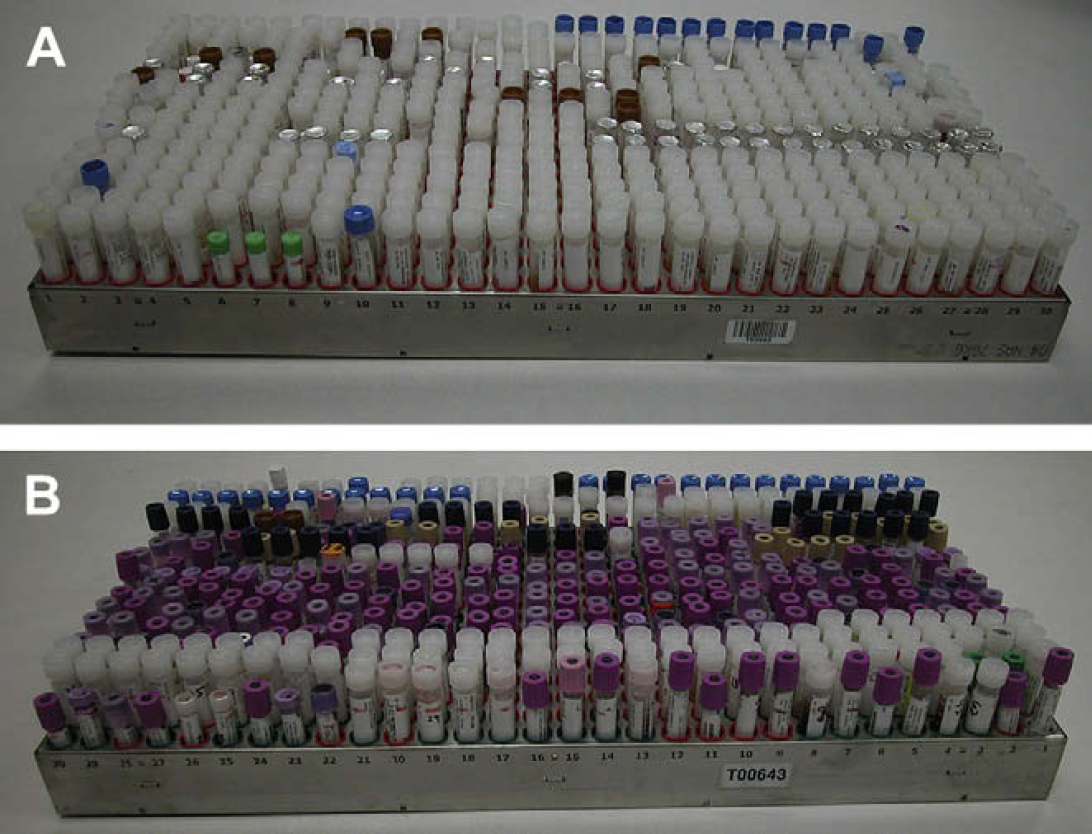
Specimen storage trays. Specimens are received in many different tube formats as shown above and are accommodated in the specimen storage trays. (A) A tray filled primarily with the 15-mm OD transport tube (capped and foil sealed) and a few other 12- and 15-mm tubes are also present. (B) A tray composed primarily of 4-ml vacutainers (12-mm OD) and other 15-mm OD tubes.
The tube removal workcell is divided into four sections (Fig. 3). The first section houses the SLC 5/05 series programmable logic controller (P/N 1747-L551, Rockwell Automation Allen-Bradley, Milwaukee, WI) which coordinates pneumatic function, optical position verification, and timing. In addition, a small air reservoir tank connected to house air (120 PSI) is also located here. Above the control unit are two pneumatic cylinders, orientated for X and Z axes travel (P/N MY1M32–500-HS-Y59BZ, SMC, Indianapolis, IN and P/N DLB-25-L-B-700-D-00-1, DE-STA-CO, Auburn Hills, MI) and the collection assembly, which is composed of a 31-position pneumatic manifold with aluminum finger supports that fit between the tube rows. The fingers are covered with a 0.75-in. long flat fire hose (woven polyester fiber wrapped polyurethane hose, P/N 235070251C, Axmen Fire Equipment, Missoula, MT) with one end sown and sealed with silicon. The fire hose is inflated (15 PSI) to pinch the specimen tubes between the fingers for removal. The collection assembly is attached to the Z-axis cylinder and raises the tubes from the tray whereas the Z-axis cylinder transports the fingers in and out of the tray presentation area. The pneumatic cylinders and tray presentation sections are separated with barrier bars that are interdigitated between the fingers (Fig. 4). The fourth section is for biohazardous specimen collection. Access doors into the tray presentation and pneumatic areas have been incorporated for instrument maintenance.
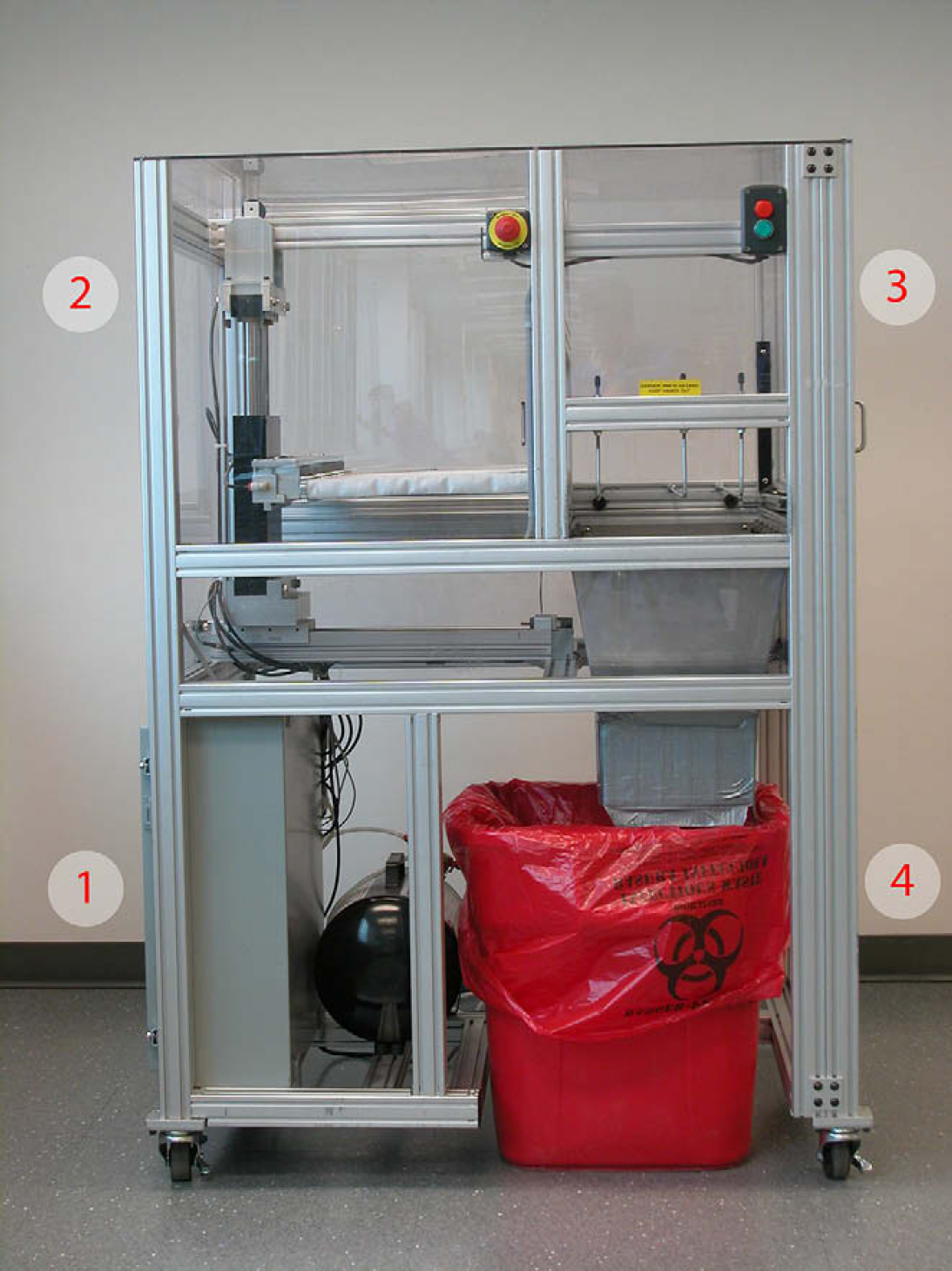
The specimen tube removal workcell. The automated specimen removal workcell has four different working sections. The lower left quadrant houses the control unit (1) with pneumatic cylinders (2) located above it. The upper right quadrant is for tray presentation (3) with the biohazardous waste bin (4) located below.
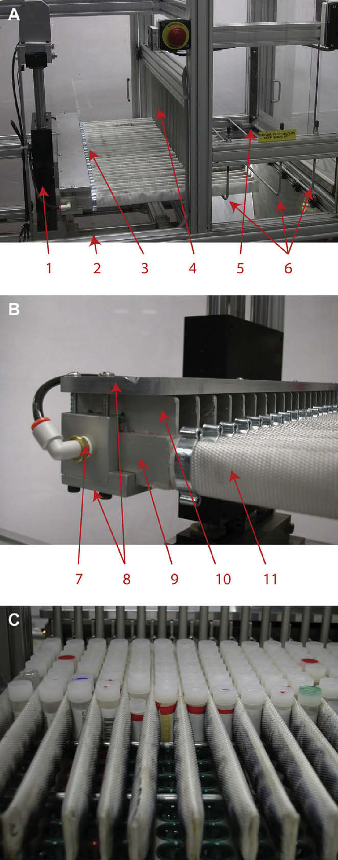
Detail of the specimen collection assembly. (A) The interaction of the collection assembly with the tray presentation area consisting of the Z-axis cylinder (1), X-axis cylinder (2), collection assembly (3), barrier bars (4), tray ejector (5), and tray hold-down rods (6). (B) An enlargement of the collection assembly highlighting the manifold (7), finger-support plates (8), pneumatic coupling (9), finger (10), and fire hose (11). (C) The collection assembly interacting with a storage tray for tube removal. The fingers are extended through the barrier bars and between the specimen tubes. The fire hose is inflated, pinching the specimen tubes before being lifted from the tray.
For tube disposal, a specimen tray is manually presented to the workcell and slid to a preset stop. At this point, the disposal cycle is initiated. Tube disposal begins with the collection assembly inserting the fingers between the barrier bars and the rows of tubes. With the finger position verified, the fingers are inflated, pinching the specimen tubes. The collection assembly is raised, pulling the tubes from the specimen tray. The tray, which is held in place by hold-down rods traversing the tray perpendicular to the finger motion, is then partially ejected. After the tray has been manually removed from the workcell, the collection assembly lowers and the fingers are deflated. Upon retraction of the collection assembly, the tubes are “racked” from the fingers as they come in contact with the barrier bars and fall through the waste shoot into the biohazard disposal bin. The total cycle time for tube removal is 10 s as shown in Figure 5.
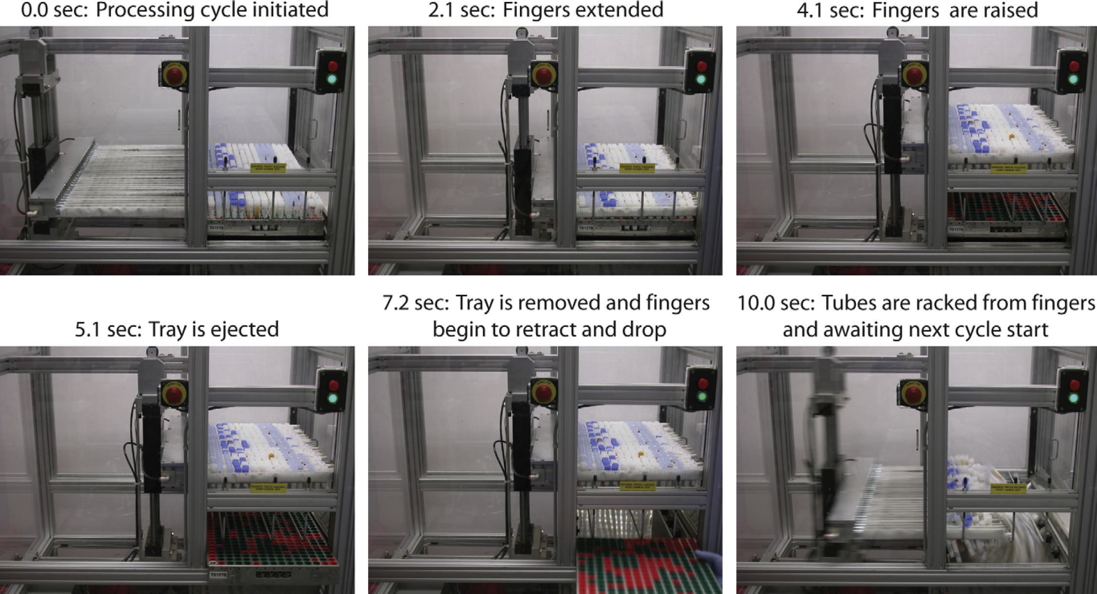
Tube disposal cycle. Each step of tube extraction is shown and time correlated. The disposal cycle is initiated by pushing the green start button (0 s). The collection assembly is moved extending the fingers into the tray (2.1 s). The fingers are then inflated and the collection assembly raised (4.1 s) after which the tray is then ejected (5.1 s). Upon removal (7.2 s), the collection assembly retracts dislodging the tubes from the fingers (10.0 s). The workcell is now ready for initiation of next disposal cycle.
Workcell Evaluation
The current system was evaluated to determine performance as a function of time required for processing trays and incidence of incomplete tube removal. Initial trials of the work-cell with room temperature standard transport tubes showed complete removal of all tubes from the trays. However, when the system was first implemented with the specimen storage system, occasional complete failures would occur. These failures were traced back to trays being removed from the freezer for immediate tube removal. This was solved by removing trays from the freezer and allowing them to thaw thoroughly before their placement in the workcell.
However, a few tubes were still inappropriately retained in 95% of the trays. Analysis of 210 trays (Fig. 6) showed that when filled predominantly with the standard transport tube, on average 2–3 tubes were retained per tray. Trays consisting predominantly of nonstandard tubes and vacutainers had much greater rates of retention (upwards of 30+ tubes). The primary cause of tube retention was interference between the tube label and the tray collet (Fig. 7). Inspection of these failed tubes revealed that tubes with heights ∼80 mm (4-ml vacutainers) would have labels extending beyond the end of the tube. This excess label would eventually crumple up and adhere to the bottom of the tray or catch on the collets, retaining the tube in the tray. Label delamination as well as folds and creases can catch on the collet preventing tubes from being removed.
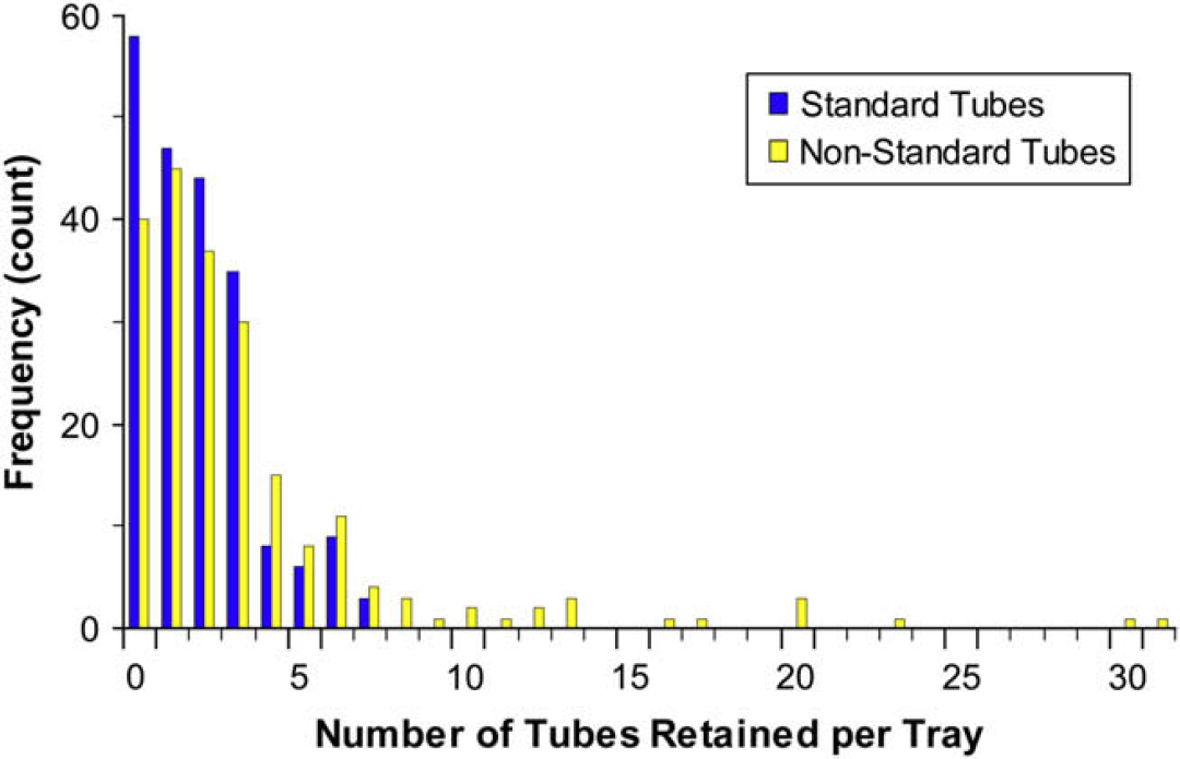
Incidence of tube retention. The incidence of tubes left in the tray after extraction. On average, 1.8 standard 15-mm OD transport tubes and 3.4 random specimen tubes are retained.
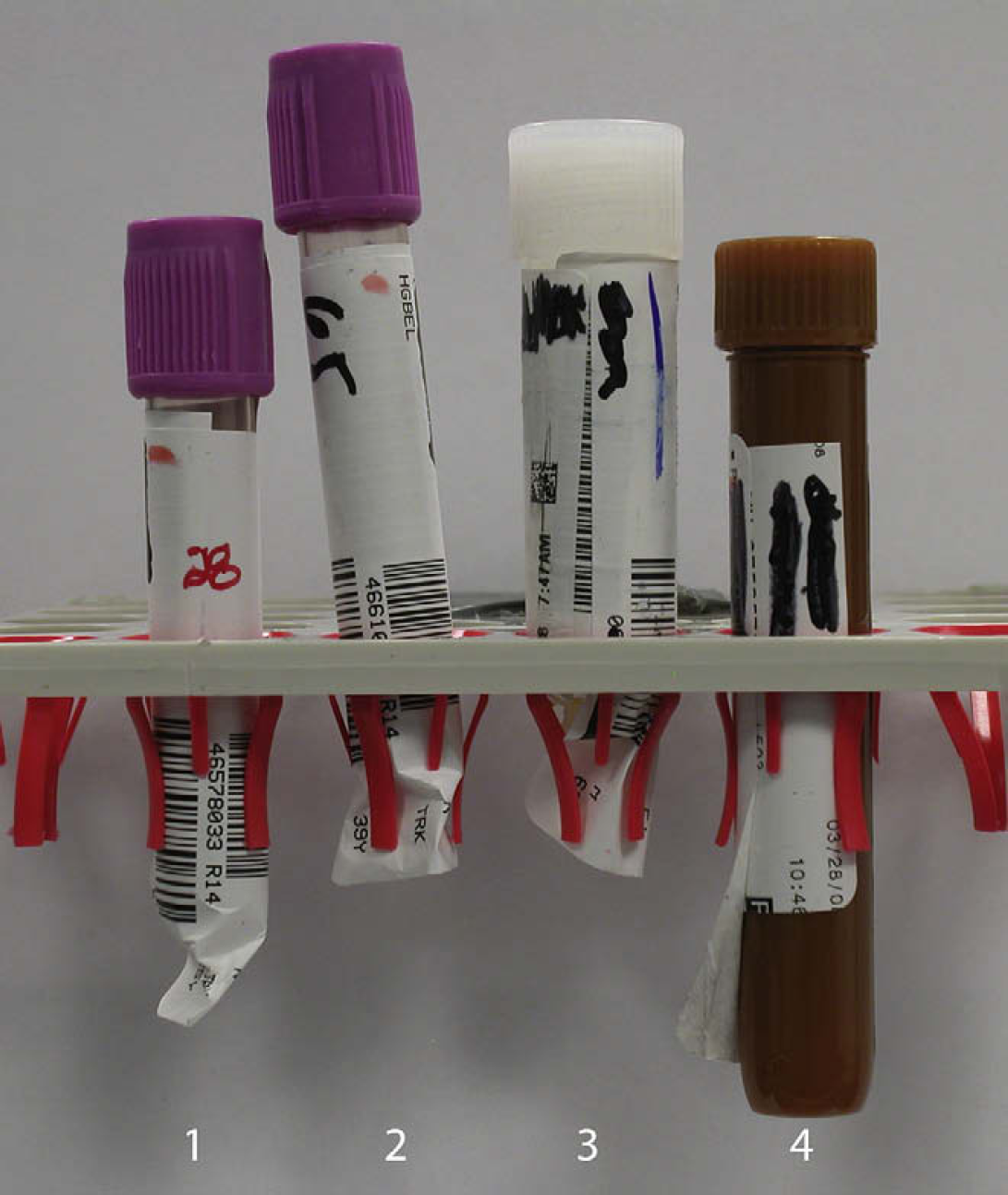
Common causes of tube retention. The major cause of tube retention is the interaction between the label and the tray centering collets. For tubes 1 and 2, the labels extended beyond the end of the tube and have crumbled. The folds of the label then catch on the collet preventing removal as seen in tube 2. Tube 3 was oversized due to excess labels and forced into position by the autosorter. Tube 4 shows a standard 15-mm transport tube with a delaminated label which can catch and adhere to the tray collet.
The FTE requirements for tray processing were determined for both the manual and automated procedures. Manual extraction of all the tubes from the tray requires on average 3.5 min. Additional time was required for waste bin preparation and removal for every three trays thus requiring a minimum of 1 FTE for weekly tube disposal. Implementation of the tube removal workcell reduced the tray handling time to 0.36 min/tray. This lowered the FTE requirement to 0.18 for specimen tube removal from the trays, a sixfold savings. The manual processing of retained tubes had little impact on the processing time. The average 2–3 tubes left in the tray are quickly discarded into the waste bin while the workcell is processing. However additional time, up to a minute, may be required when retained specimens were in excess of 10.
Full integration into the automated storage/retrieval system for complete hands off operation is dependent on increasing the number of trays with 100% tube extraction. Under the current design, the tubes momentarily restrain the Z-axis cylinder from lifting. In the future, the Z-axis cylinder may be replaced with a servo-driven ball-screw to increase the lifting strength. The additional power would also allow the fingers to be constructed out of stainless steel for increased rigidity. The tubing used to cover the fingers, as constructed, is prone to air leakage and under inflation thus allowing some tubes to be retained. We are investigating thermal welding of the fire hose for sealing to eliminate this issue. However, the major improvement for specimen extraction will come on line later this year, when ARUP converts to a smaller label that fits on 75-mm tubes.
Conclusions
High volume reference laboratories have high-volume tube disposal needs. Incorporation of a tube removal workcell into ARUP specimen management has reduced the labor requirements by sixfold, lowering staffing requirement as specimen volume continues to increase and decreasing biohazardous exposure.
Acknowledgments
We thank Tess Calder and the automated specimen management team for access to their department during the validation and Vladimir Blackbolt for manuscript review.