
Abstract
Microarrays simultaneously screen tens to thousands of biosamples to observe biochemical activities in protein—protein, protein—nucleic acid and small molecule interactions. In this high throughput analysis, rapid and reliable printing technologies are highly desired with less deterioration on biosamples during process. This study introduces several micro-contact printing systems to print out multiple proteins simultaneously, uniformly and continuously with batch-filling capability for rapid microarray formation, with very gentle process for biosample preservation. This printing system consists of two chips, including a micro-filling chip and a micro-stamp chip, for rapid/accurate registration and batch operation. The micro-filling chip can simultaneously transfer numerous protein solutions into the micro-stamp chip in seconds by capillary force without cross-contamination, while preserving the functionality of proteins. Different proteins can be dispensed into the corresponding channels and driven into the tips of the micro stamps. The micro stamp can be then brought to contact with the substrate to produce bio-fluid spot arrays. These devices have a potential to be expanded to a high throughput system for simultaneously printing hundreds of bio-fluid spots for hundreds times in minutes, and to form dense bio-microarrays for disease diagnosis or drug screening.
Introduction
Protein microarrays 1 -3 have been applied to simultaneously screen tens to thousands of biosamples to observe biochemical activities in protein–protein, protein–nucleic acid, and small molecule interactions. This technology supports high-throughput analysis and has great potential in basic molecular biology research, disease marker identification, toxicological response profiling, and pharmaceutical target screening. 4 -6
Several methods have been developed for generating microarrays, including micro-needle arraying, 7,8 ink-jet printing, 9,10 air dispenser jetting, 11 -13 piezoelectric inkjet, 14,15 electro-spray deposition, 16 -18 biological laser printing, 19 dip pen nanolithography, 20 -22 and micro-contact printing. 23 -28 Photolithography methods may pose biocompatible issue, and cannot be easily applied to many different types of proteins on a chip at one time. Robot controlled micro-needle array, although matured in DNA array formation, has the drawbacks such as high cost, and serial and long process in sample loading, printing, and washing. Besides, the tip cleaning process might be unavoidable to eliminate cross-contamination. In ink-jet printing technology, the ink-jet printer needs precise pressure control for each nozzle to reach uniform deposition during the high-speed printing. The printing apparatus may be very complex for accommodating many different types of proteins for printing if each of the protein samples needs to be ejected out from its own chamber to prevent cross-contamination. Besides, the formed spots may not be in regular shape due to the ejected droplets impinging on chip surface at high speed. Electro spray and laser ejection may also pose issues of irregular proteins spots and undesired effects on proteins by the applied energies.
Unlike robot bin sequential printing, micro-contact printing 29,30 can rapidly print hundreds of uniform spots of the same bioreagents in parallel with conformal contact. For preventing the bio-fluid from attaching to neighboring stamp by surface tension, 31 traditional contact printing transfers proteins 23,32 using stamp immersed with protein solution and then dried under a stream of nitrogen. A silicon microwell 26 used to ink the polydimethylsiloxane (PDMS) stamp with protein solutions enables the stamp to print four protein types with a pitch of 350 μm after rinsing and drying. Otherwise, microfluidic networks 33 -35 and PDMS microfluidic spotters 36 enable the multiple solutions to flow on the contact area on the substrate. However, those methods do not allow the easy generation of patterns of different inks and the protein structures may change during drying. 37 This study introduces several specially designed micro-contact printing systems to print out multiple proteins simultaneously, uniformly, and continuously with batch-filling capability for rapid formation of protein microarray, while preserving the biosample functionality and preventing cross-contamination.
Back-Filling Micro-Stamper Chip
System Introduction
Among various micro printing schemes, most of which can deal with very limit types of proteins at one time; yet the back filling of a micro-stamp chip 27 including reservoirs with PDMS stamps can parallelly print 4–10 proteins simultaneously. The back-filling stamp chip demonstrates the basic functionality of printing single to several proteins in one stamping process without being dried under a stream of nitrogen. This stamping system, as shown in Figure 1, can be filled with different biosamples on the chip backside reservoirs and then prints out protein arrays on a bioassay chip in parallel. The concept can be easily expanded to spot hundreds to thousands of different biosamples simultaneously. The micro-stamp chip comprises three components: a micro-stamp array, an embedded micro-channel array, and reservoir units. In Figure 1, different biosamples can be dispensed into different reservoirs in millimeter size and directed by surface tension to the tips of the micro stamps through the micro channels without pumps or valves. The biosample-filled micro stamp is then brought into contact with the bioassay chip to generate droplet arrays of the biosamples. After being briefly pressed on the bioassay chip for 30 s, the micro-stamp chip is released, and then biosample arrays form on the bioassay chip simultaneously for further bioprocess. The micro-stamp array comprises elastic PDMS thus can make conformal contact with nonplanar surfaces.
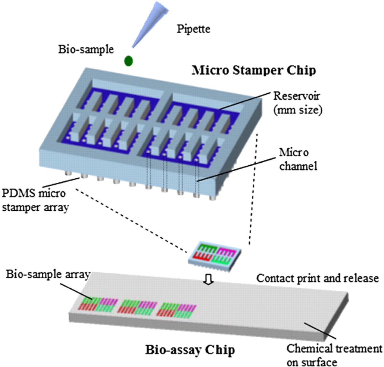
Schematic diagram of the backfilling micro stamping system.
Manufacturing and Printing Results
The stamp was fabricated by the incorporation of SU8 lithography and PDMS molding. 29 The fabricated PDMS stamp array is shown in Figure 2a. To verify that the stamping system can perform uniform protein printing, the micro-stamp chips were used to spot Cy3 conjugated antimouse immunoglobulin G (IgG) onto the bioassay chip. The bioassay chips were fabricated by glass slides with surfaces modified by aminopropyltrimethoxysilane (APTS) and then bis-sulfosuccinimidyl suberate (BS3). Before stamping, O2 plasma treatment was used to transform the SU8 channels and PDMS stamps hydrophilic. The fluorescence of the stamped protein arrays was scanned in GenePix 4000B scanner (Axon Instruments, USA). Figure 2b shows the stamping result of Cy3 (0.001 g/L) diluted in phosphate buffered saline (PBS) with 30% glycerol solution. The amplified cross section of the SU8 flow channel and the PDMS stamp are shown on the Figure 2c. The print results by the stamp (outside diameter: 200 μm, inner hole diameter: 50 μm) with Cy5 fluorescence (0.01 g/L) in PBS solution is illustrated in Figure 2d. The stamped protein spots displayed uniform features.
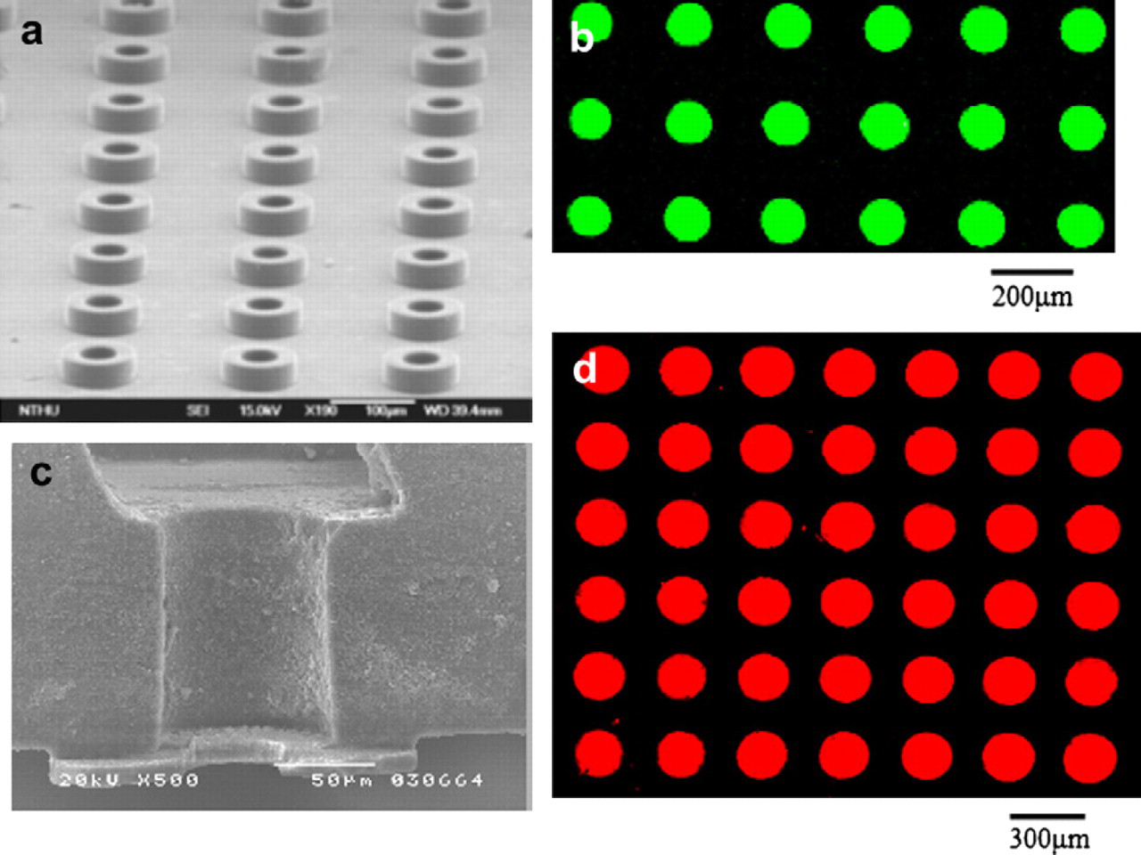
(a) Scanning electron micrograph showing PDMS stamp array (b) Fluorescence image of the print results by the stamp (outside diameter: 100 μm, inner hole diameter: 50 μm) with Cy3 fluorescence (0.001 g/l) in PBS solution (c) SEM image of the amplified cross section of the flow channel of the stamp chip (d) Fluorescence image of the print results by the stamp (outside diameter: 200 μm, inner hole diameter: 50 μm) with Cy5 fluorescence (0.01 g/l) in PBS solution.
Surface Property and Viscosity Effects on the Formation of Droplet Arrays
In the robotic metal pin system, Reichert found that the surface wettability of the substrate and the viscosity of the bio solution affected the printed feature size. 38 However, the back-filling elastic stamp differs from pin-printing process owing to its open channel structures and material deformable nature, resulting in more complex capillary flow and more conformal contact with substrates than those of solid pin process. Therefore, the study investigates the dynamic printing process of stamper array, the effects of surface wettability, and solution viscosity of formed droplet size by both simulation and experiment. 39 Figure 3 shows the experimental results of the effect by surface wettability and solution viscosity on droplet size, and reveals that the printed spot size increases with substrate wettability increasing. Otherwise, the printed spot size decreases with solution viscosity increasing. 3D simulation is used to discover the dynamic stamping process and the drop breakdown process, as illustrated on the Fig. 4.
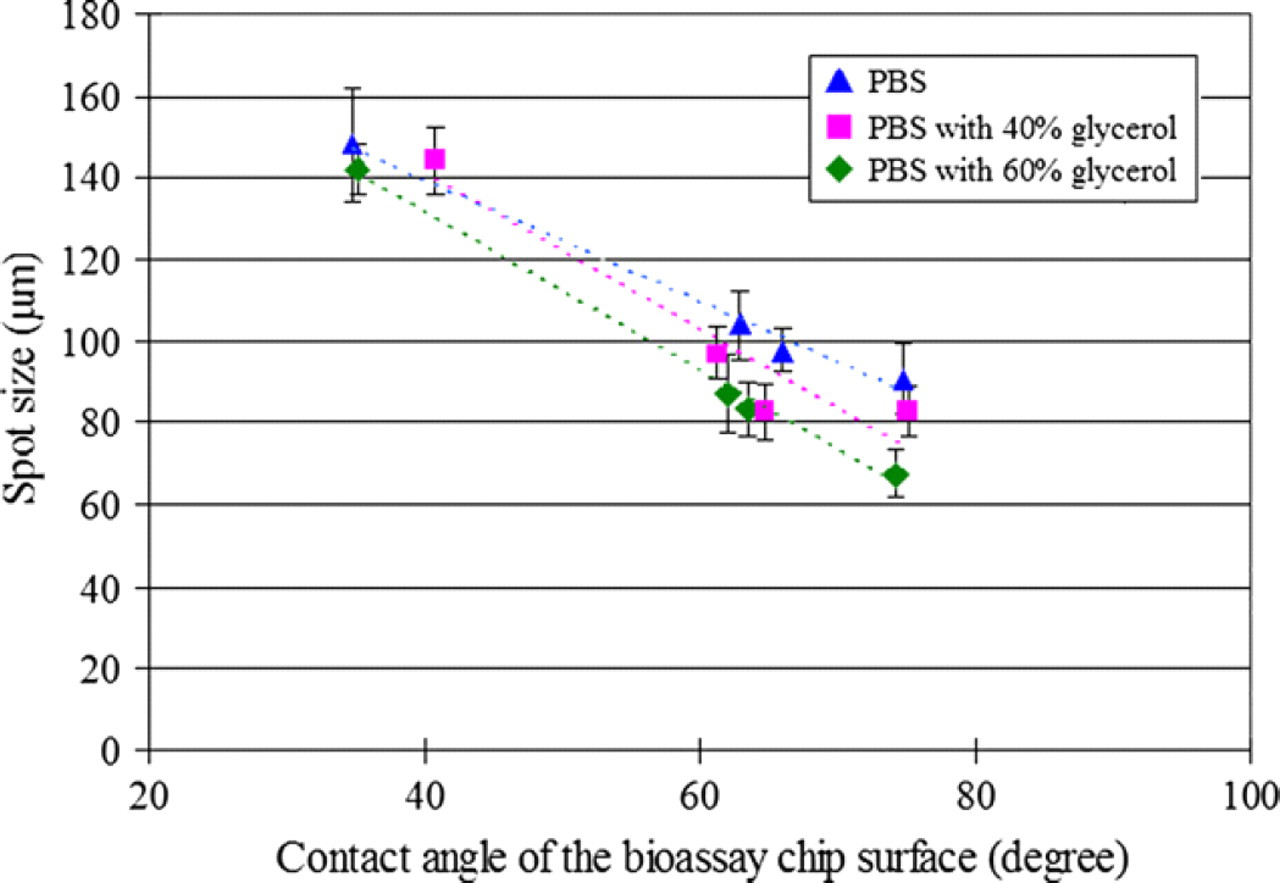
Experiment result of spot size variation on the bioassay chip surface with different wettabilities.
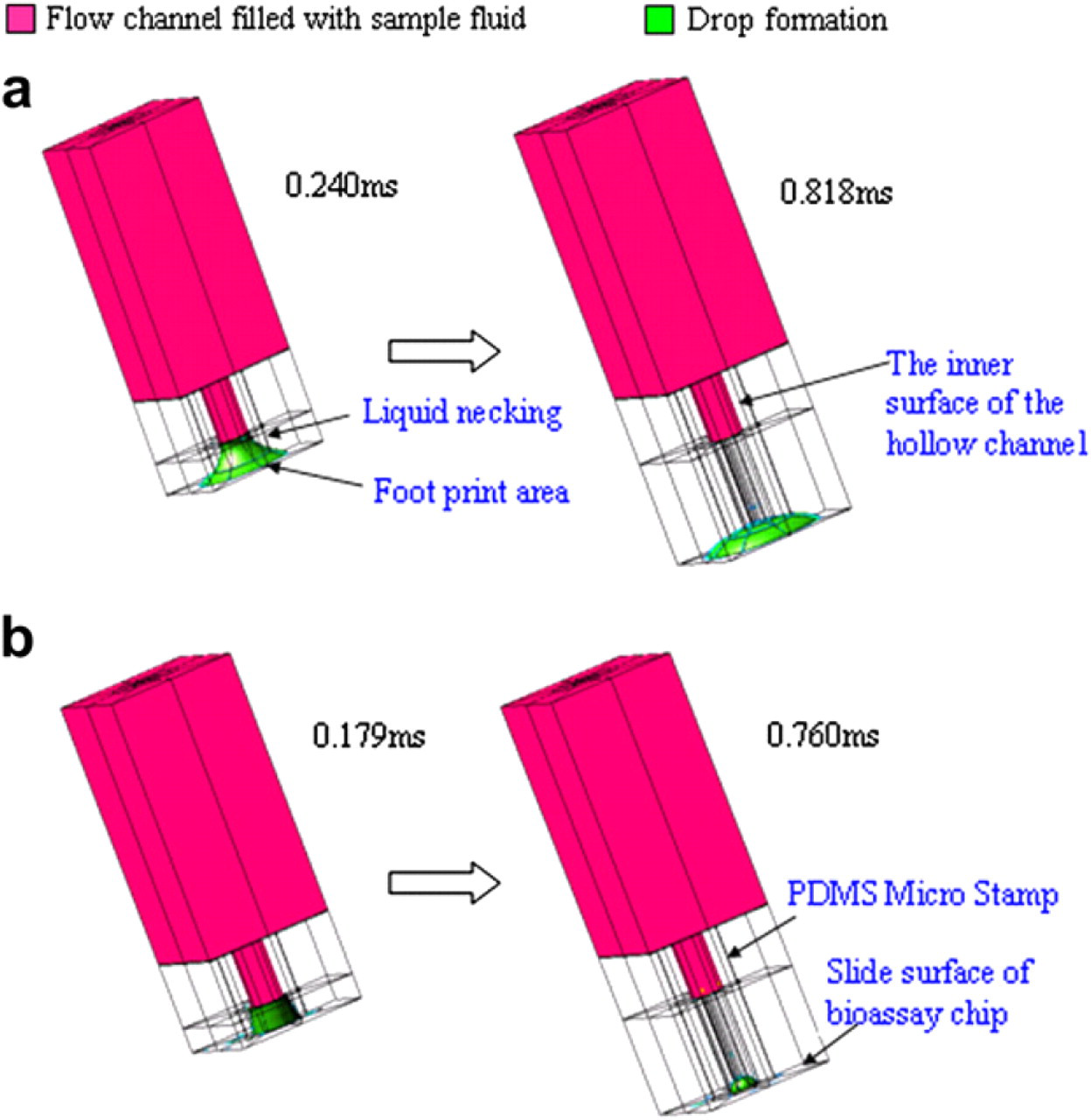
Dynamic simulation of micro-stamp detaching process and drop breakdown process. (a) on higher hydrophilic surface (30o) (b) on lower hydrophilic surface (80o).
Batch-Filling and Parallel-Printing Multiple Proteins
System Introduction
To further increase the printing numbers of different types of biosamples, a batch-filling micro-contact printing system was developed 40 with the capability of batch-fill-in and in-parallel print tens of proteins in one stamping process to form dense arrays in high throughput, as the schematic shown in Figure 5. This system consists of a filling chip and a stamping chip. The filling chip can simultaneously transfer tens of proteins into the stamping chip without cross-contamination, and also preserve active protein solutions as a library before transferring. After batch filling, the micro-stamp chip can simultaneously print in parallel tens of protein solutions in a dense array without sample dry out during the operation. The entire procedure takes a few seconds, and all microfluidic fillings proceed under capillary force only.
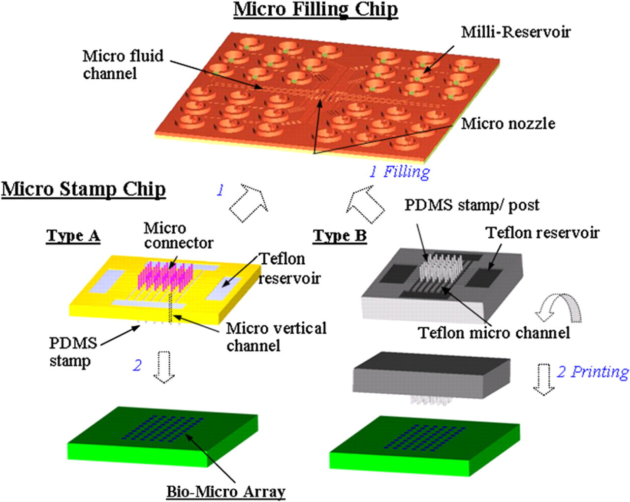
Schematic representation of microarray system for batch-filling and in parallel printing of multiple proteins. 1) The micro connectors (type A) or the PDMS posts (type B) of the micro stamp chips are connected into the nozzles of the micro filling chip, and then the bio-fluids are transferred into the micro stamp simultaneously. 2) After the filling has been completed, those two chips are separated, and then PDMS stamps are used to print in parallel numerous arrays.
In the design as displayed in Figure 5, on the top of the filling chip are reservoirs with a diameter of 1.2 mm for bio-sample loading; on the bottom are micro nozzles to transfer solutions of biosample. Micro channels connect each reservoir to the corresponding micro nozzle. Biosamples can be loaded by capillary action from a single reservoir to the corresponding micro nozzle. The filling chip is designed for batch, rather than individual, protein filling of the micro-stamp chip. Additionally, the filling chip can preserve protein in a refrigerator after its top and bottom surfaces are sealed. This study develops two types of stamping chips, A and B. In chip A, the micro connectors on top of the micro-stamping chip can be plugged into the nozzles of the filling chip to cause different bio-fluids to flow simultaneously into the corresponding stamp heads via vertical micro channels. The micro posts on the top surface of the chip B function as connectors to guide different proteins from the filling chip into the stamp heads for printing. Teflon patterns that are coated on the top of the stamp chip and the bottom of the filling chip are applied to prevent cross-contamination during the transfer of bio-fluid from the filling chip into the stamping chip. After batch filling, the stamp is brought into gentle contact with the substrate to produce a bio-microarray.
System Operation
Figure 6 presents the operation concept according to which the protein filling chip and the stamping chip perform batch filling and parallel printing. Different protein solutions were loaded into the reservoirs of the micro-filling chip using a pipette, as depicted in Figure 6a. The parallel protein fill-in process can be initiated by directly connecting the filling chip to the stamp chip. The filling chip was aligned with the stamping chip under an optical microscope. Tens of proteins were simultaneously transferred by capillary action from the filling chip into the stamp chip in seconds. Each stamp was filled with a different protein solution, as shown in Figure 6b. Teflon patterns were coated around each connector and the bottom of the filling chip nozzle to prevent cross-contamination between neighboring channels during the fill-in process. After the filling process was completed, the two chips were separated and the bio-fluid drops were remained on the top of the stamp chip separately, as shown in Figure 6c. The protein-filled micro stamp was then brought into contact with the substrate to generate bio-fluid arrays, as presented in Figure 6d, e. PDMS was used to fabricate the micro stamps; therefore, conformal contact can be achieved on rough surfaces. Finally, tens of proteins were simultaneously arrayed using this novel stamping system chip, as shown in Figure 6f.
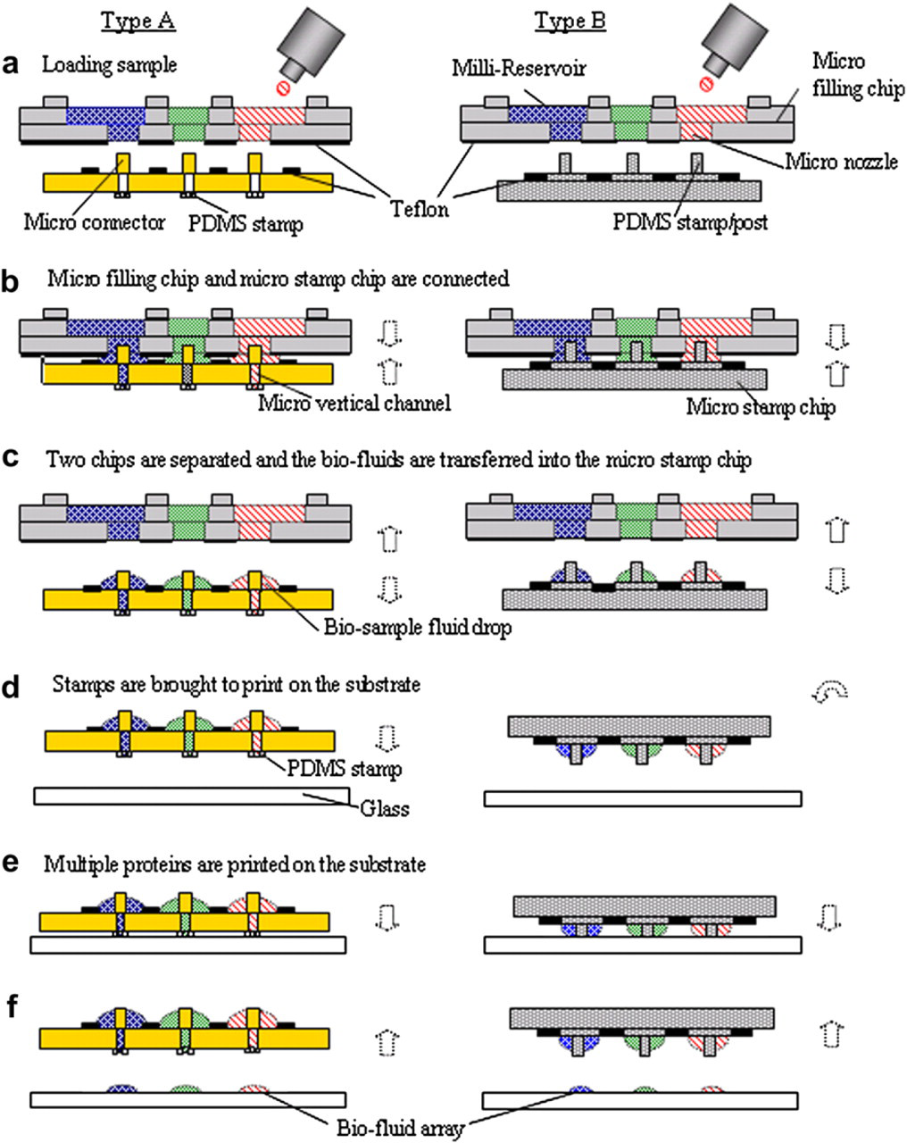
Operation of the micro filling chip and micro stamp chip system.
Manufacturing Results
The SEM images of the fabricated filling chip, 40 shown in Figure 7, reveal good structural definition. Filling chips with 36 reservoirs were successfully fabricated. On the other hand, the stamp chip was designed with barrier channels for Teflon solution guidance, Teflon pattern regulation, and a structural barrier to stop flow cross mixing on the top of the stamper chip. This barrier channel design was directly incorporated into the fabrication of two protein stamps, A and B, as shown in Figure 8a, c. In the A chip (Fig. 8a and Fig. 5 type A), specially designed Teflon channels in orthogonal directions were used to confine the Teflon solution, and both hydrophobic patterns and structural barriers were formed around the connector/chamber regions. The reservoirs for Teflon solution were located on the four sides of the chip and the Teflon solution flowed from the reservoir to the micro channels. PDMS stamp microarray were located on the bottom of the A chip as shown in Figure 8b. In the B chip (Fig. 8c and Fig. 5 type B), the stamp/post regions were made higher than the chip surface, such that the Teflon solution was confined only on the chip surface that surrounded the stamp/post regions without contaminating the stamps/posts.
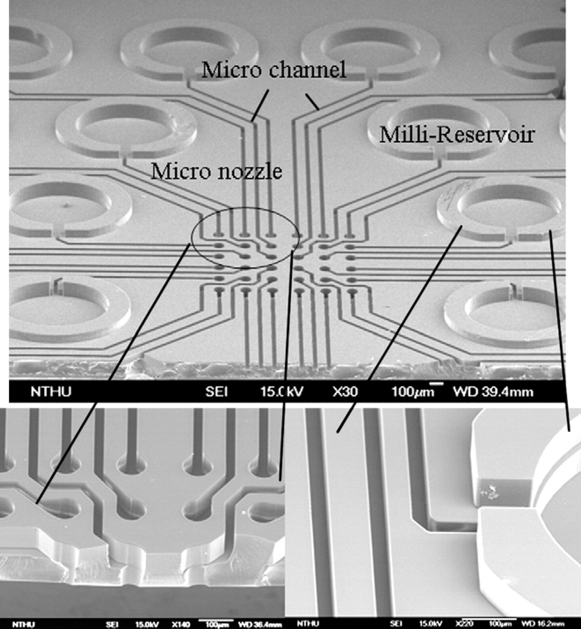
SEM images of the micro nozzle, micro channel and milli-reservoir of the micro filling chip.
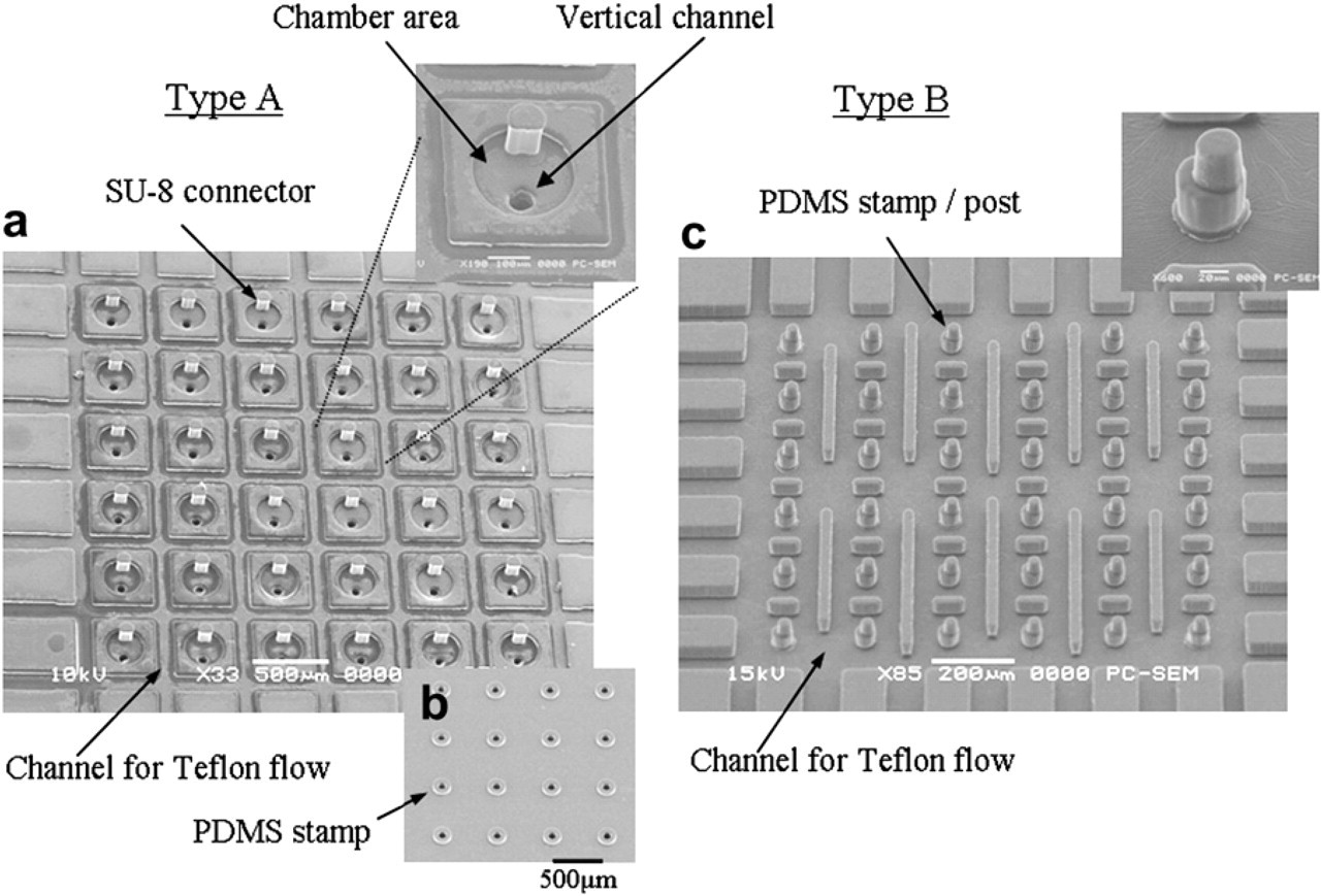
SEM images of micro stamp chip. (a) Top view of the type A stamper chip. Teflon flow channels are around the connector regions. (b) Bottom view of the type A stamper chip, PDMS stamp array. (c) Top view of the type B stamper chip, PDMS stamp/post array.
Printing Results
The stamp heads were filled with different proteins. Figure 9 presents the results of the parallel printing of 36 spots with different protein solutions using the type B stamp. The symbols represent the following. R1: antimouse IgG cy5 0.6 mL/mL, R2: antimouse IgG Cy5 0.1 mL/mL, G2: antirabbit IgG Cy3 0.8 mL/mL, G3: antirabbit IgG Cy3 0.4 mg/mL, G4: antirabbit IgG Cy3 0.2 mg/mL, G5: antirabbit IgG Cy3 0.05 mg/mL, X: solution mixing. Each spot of the microarray is associated with a different protein and allows the PDMS micro stamp to produce patterns of different inks simultaneously. The micro-filling chip can be expanded to have 100 micro nozzles, and the micro-stamper chip can be made to have 100 micro connectors. The concept of this work can be expanded to parallel print hundreds of proteins simultaneously in a single stamping following batch filling.
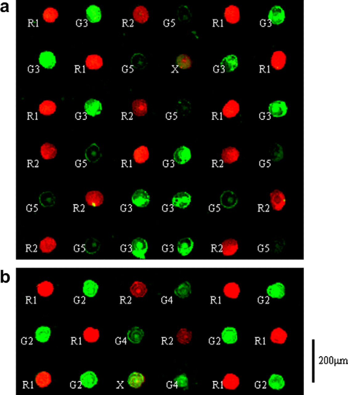
Fluorescence images of the parallel printing numerous proteins. (a) Thirty-six spots with four kinds of different protein solutions. (b) Eighteen spots with four kinds of different protein solutions.
Figure 10a shows the results of the simultaneous parallel printing of 30 spots with given concentrations of Cy3 using a type B stamp. Different concentrations (1: 1 mg/mL, 2: 0.8 mg/mL, 3: 0.4 mg/mL, 4: 0.2 mg/mL, 5: 0.05 mg/mL) were printed in an orderly manner in each row. Those solutions were antirabbit IgG Cy3 in PBS solution with 30% glycerol. The logarithm of the concentration data was linearly related to the logarithm of the fluorescence intensity, as presented in Figure 10b.
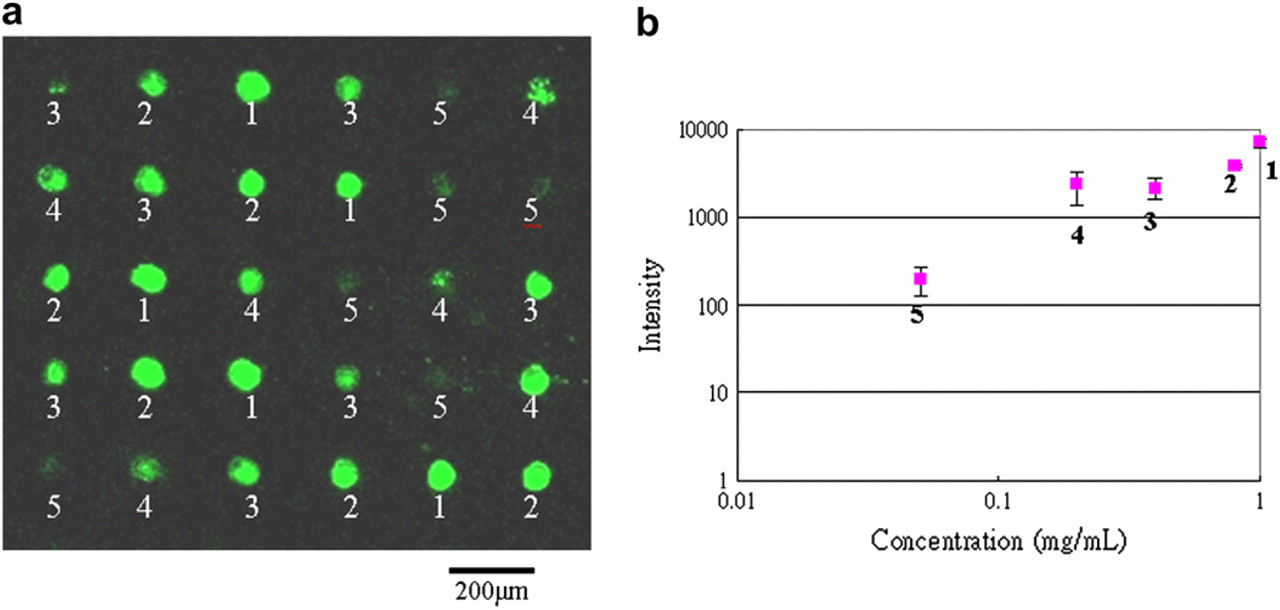
Simultaneously parallel printing 30 spots with the different concentration solution.
Line-up micro-stamper chips
With providing larger reservoir of the biosample storage of the stamper chip, a line-up micro-contact printing chip was able to simultaneously print multiple proteins and continuously print hundreds times after batch filling once. The filling chip can simultaneously transfer tens of protein solution in seconds into the micro-stamper chip by capillary force during these two chips conjugation. Teflon-coated micro channel was designed to avoid cross-contamination during in-parallel filling process. Figure 11 illustrates the design concept of the line-up micro-stamper system, which consists of a micro-filling chip and a micro-stamper chip.
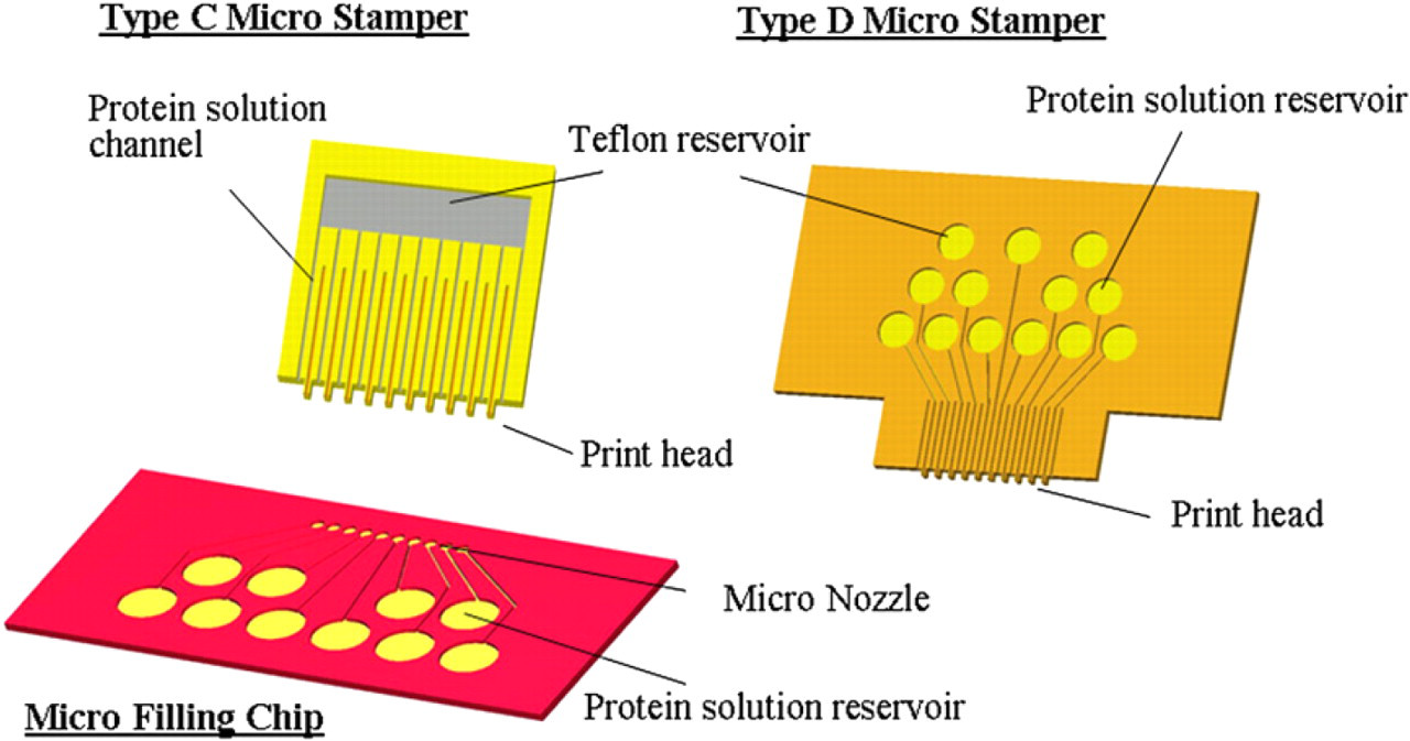
Schematic representation of the line-up micro stamp array system: Type C stamper chip can be filled from a different micro filling chip. Type D stamper chip is designed with the reservoirs directly on the topside for pipette dispensing.
The micro-filling chip can contain protein solutions in different reservoirs free from cross-contamination and be kept in refrigerator before using (Fig. 12a). When the micro-filling chip contacted with the micro-stamper chip, different protein solutions parallelly filled in the stamper chip through the stamp head of type C. By the capillary force, protein solutions flowed into the micro channel of the stamper chip (Fig. 12b) in seconds. The protein-filled micro stamper was then separated (Fig. 12c) and brought into contact (Fig. 12d, e) with the bio-reaction chip to generate sample arrays simultaneously in parallel (Fig. 12f) for further bio-processing. Figure 12g illustrates the protein solution was loaded into the backside reservoir of the type D stamper chip. After loading, the stamper chip stood and contacted print on the bottom plate of the 96 well as shown in Figure 12h-j.
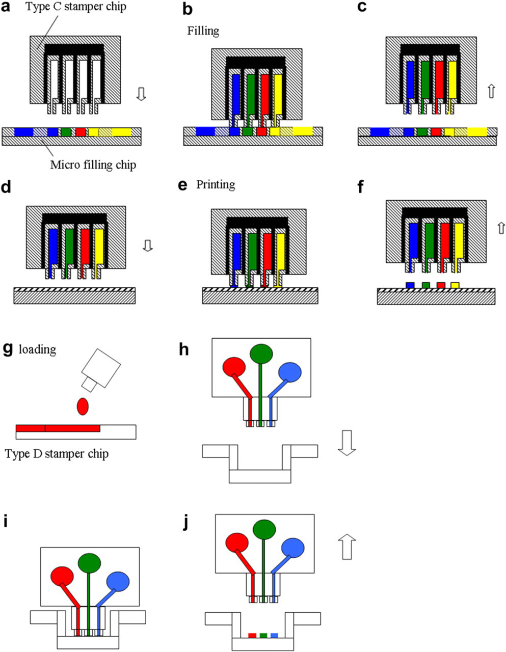
Operation process: (a-f) Type C stamper chip; (g-j) Type D stamper chip print in 96 well.
Figure 13 shows the SEM picture of the fabrication result of the micro-stamper chip. The stamper chip can continuously print a hundred times on a glass slide after filling once as demonstrated in Figure 14. Antirabbit IgG Cy3 0.005 g/L and antimouse IgG Cy5 0.1 g/L in PBS solution with 30% glycerol were used in this experiment. The standard deviation of the spot size is under 7.1%, and that of the intensity is under 8.3%. This stamper chip system can parallel fill-in tens of samples, simultaneously print multiple proteins, and continuously print hundreds times after filling once for rapid protein microarray formation.
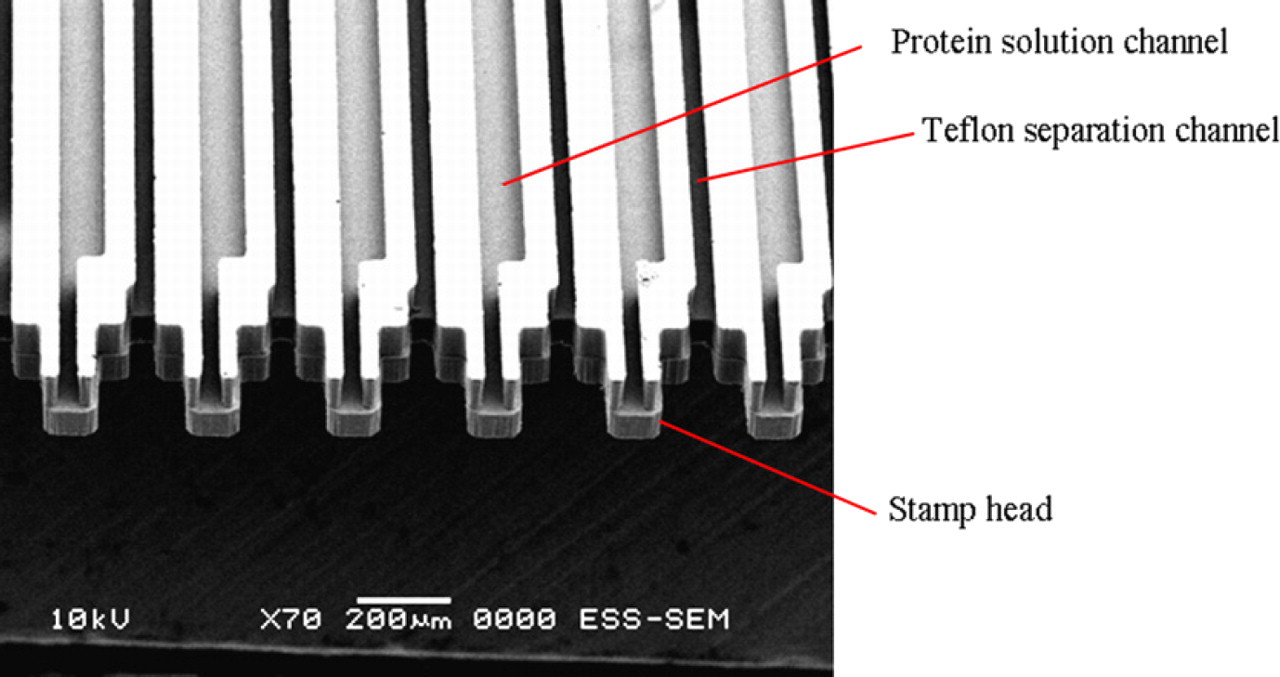
SEM picture of the stamp head of the line-up micro stamper chip.
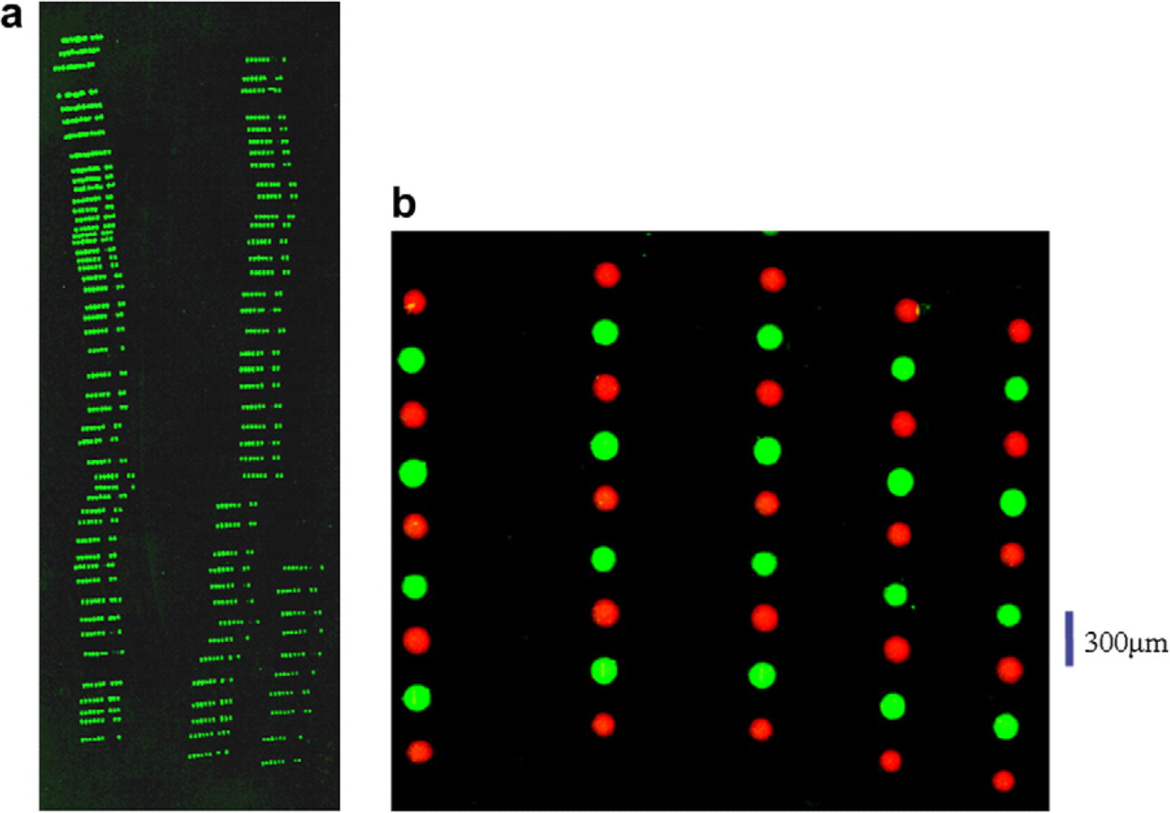
(a) Fluorescence image of the continuously printing 100 times on glass slide. (b) Fluorescence images of parallel print multiple proteins.
Comparison
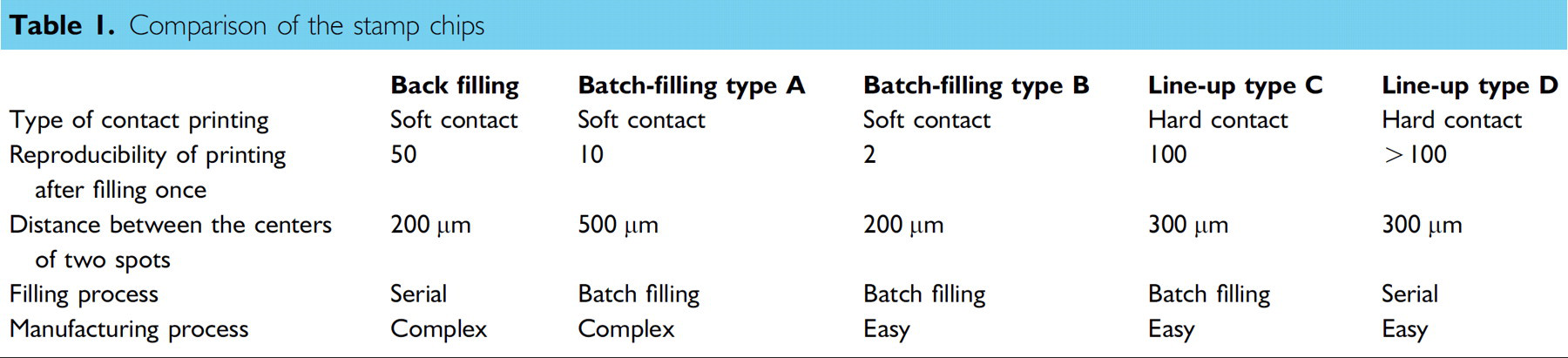
The batch-filling stamper chips of types A, B with PDMS stamp are soft-contact printing. The line-up stamper chips of types C, D with Su8 stamp are hard-contact printing. Otherwise, the types C, D chips can print repeatedly more times than the types A, B chips can because the chamber reservoir design allows an additional protein solution to be contained. Furthermore, the manufacturing processes of the types B, C, and D chips are simpler than that of type A. The comparison of the different stamper chips are described in Table 1.
Comparison of the stamp chips
Conclusion
This study demonstrates several types of micro-array stampers for bio-microarray rapid formation without deterioration. In the back filling and disposable micro-array chip, uniform parallel printing has been successfully performed. Both experimental and simulation results verify that the spot size of the soft printing increases with the increasing of surface wettability of bioassay chip. Furthermore, the more viscous biosample solution carries out the smaller droplet size. On the other hand, the batch-filling system can passively and gently print in parallel tens of bio-fluids in an array. This chip system can have a micro-filling chip to preserve and transfer bio-fluid, and a micro-stamp chip for parallel bio-fluid printing. The micro-filling chip successfully transferred by capillary action tens of bio-fluids from a filling chip into a micro-stamp chip during conjugation. A Teflon channel barrier was used to prevent cross-contamination and the spread of fluid during filling. Thirty-six proteins were simultaneously printed in parallel on a substrate to form a bio-fluid microarray using this in-parallel-printing system. The printed array has a spot distance of 200 μm, a spot size of 50 μm, and a spot size variation of less than 5%. The concept can be expanded to spot simultaneously hundreds of biosamples. Moreover, a line-up micro-contact printing chip demonstrated the functionality of parallelly printing multiple proteins and continuously printing hundred times after batch filling once. Pack each line-up printing chip together to form 2-D printing array is the future developed work. The micro stamper was used to print out different proteins simultaneously, uniformly, and continuously for rapid forming protein microarray for disease diagnosis, drug discovery, and research into bio-molecular interactions.
Acknowledgment
The authors would like to thank the National Science Council of the R.O.C., Taiwan, for financially supporting this research under Contract No. NSC-94–2323-B-007–004, 005.