
Abstract
A fully automated robotic system was developed and deployed in-house in a modular way to meet the needs of a high throughput chemistry laboratory. The main system components consist of a Stäubli TX60 industrial robot and a Vapourtec V-10 evaporator, with control software by Aitken Scientific. A custom server application was written by Stäubli robotics to interface the robot and control software. The design was done using SolidWorks Computer Aided Design to speed up development, with out-sourced software development and hardware procurement or fabrication. Both hardware and software were modularized such that components could be reused in the future. An industrial robot and original equipment manufacturer (OEM) components were used to improve reliability and minimize support. A custom gripper was designed using a Schunk MPG50 pneumatic two-finger parallel actuator with stainless steel fingers. An injector station was designed to simplify and automate large volume evaporations, with built-in self-cleaning. Custom fabrication of racks, grippers, etc was done using local precision engineering firms. Providing full documentation and training allows support to be done by third-party service engineers. Initial data show that the system is both intuitive and reliable in use.
Keywords
Introduction
Scientific processes in Research and Development are notorious for changing, often rapidly. This is a challenge to automation projects as the processes can be changing quicker than systems can be deployed, so limiting usefulness. Reuse of components, including software, is thus a compelling justification, minimizing risk. Industrial robots, with minimal support issues and down time, are a seriously attractive option for laboratory applications, but the lack of integratability into laboratory systems, safety issues, and expert knowledge requirements has limited their general use in small workstation applications.
The Vapourtec V-10 evaporator 1 is a compact standalone solvent evaporation system developed for use in laboratory environments. To maximize the throughput, a system was designed that allowed racks of vessels to be scheduled completely unattended. The needs of a high throughput chemistry laboratory, with open access requirements, were critical to the successful deployment of a solution.
Design Considerations
Design Phase
A prototype robotic system 2 using a Kawasaki FS02N robot and V-10 evaporator was developed by the Technology Development group at GlaxoSmithKline (GSK). To meet the needs of an open-access high throughput chemistry laboratory, and ensure that support needs and safety standards were fulfilled, the project team revisited all aspects of the prototype.
The in-house project design team at GSK used SolidWorks
3
3D-Computer Aided Design (CAD) to rapidly design the system. SolidWorks models of many third-party industrial components, including the Stäubli robot, were readily available from vendors or web sites such as PowerPARTS
4
and Traceparts.
5
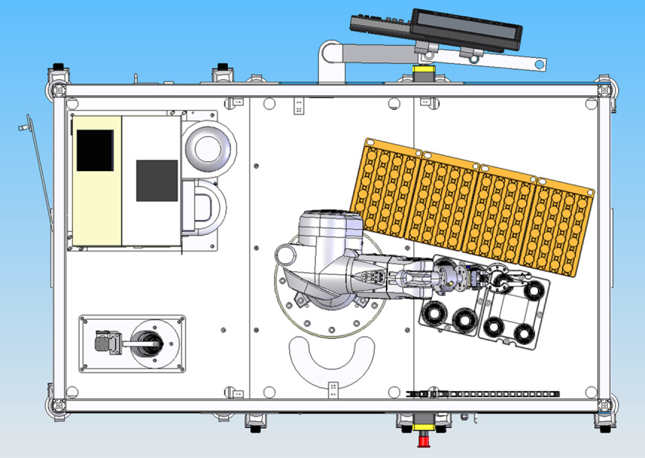
This enabled a library of parts to be used to build assemblies and subassemblies of complex systems so allowing reuse in future projects. Animation and simulation let the design engineer check for problems and allowed virtual design iterations. Parts were quickly drawn using this CAD package, with little CAD knowledge. The system described in this article consisted of many hundreds of individual parts all mated together to give an accurate representation of the system. Saving of the assembly design in SolidWorks eDrawings format allowed the design engineer to e-mail 3D-CAD models to the scientist in a form suitable for easy visualization of the system. Changes were thus easily made before procurement and building started (Figs. 1 and 2).
Isometric Computer Aided Design drawing of system at design stage. Plan view of system.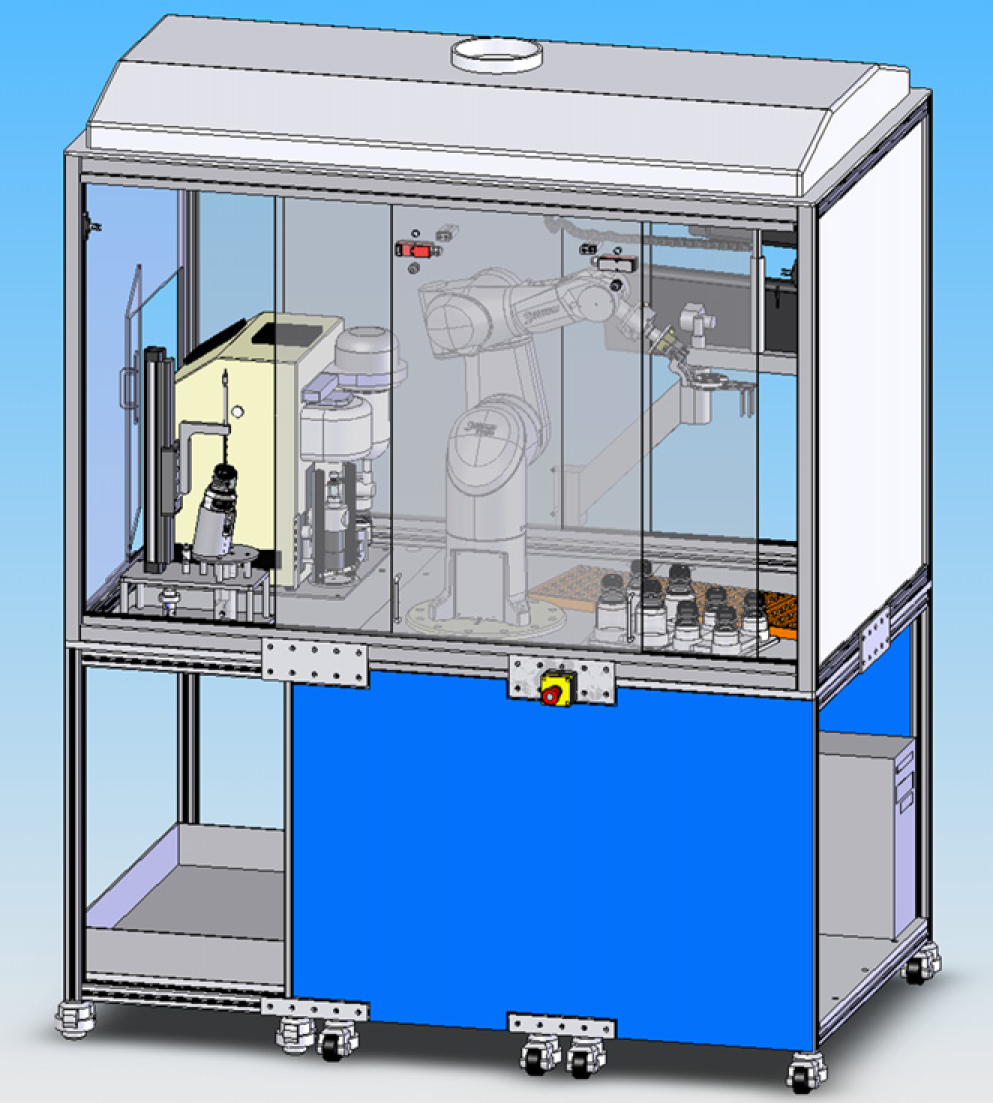
Vapourtec V-10 Evaporator
The Vapourtec V-10 is a standalone evaporator
1
designed to evaporate small volumes of solvent quickly. Because of this capability, and to justify the capital outlay of such a piece of equipment, automation was highly desirable. The V-10 also has the capability of processing large volumes of solvent via a series of valves and tubing. Attaching the end to a canula needle allowed automation, as a vessel just needed to be brought to the end of the needle, using either a robot or liquid handler. Due to the variation in vessel sizes, different configurations, open access, and other requirements, this system was designed using a robot. To integrate with the rest of the system, a software driver had to be written. It was also decided to add additional sensors, hardwired into the robot I/O, to prevent robot collisions. A microswitch was used at the bottom of the lift, and a digital sensor to detect whether a vessel was on the lift (Fig. 3).
Computer Aided Design of V-10 showing location of sensors and mounting brackets.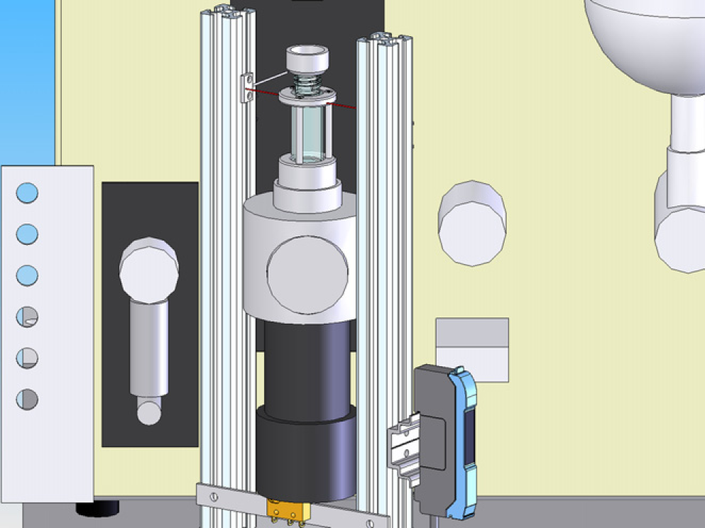
Injector Station
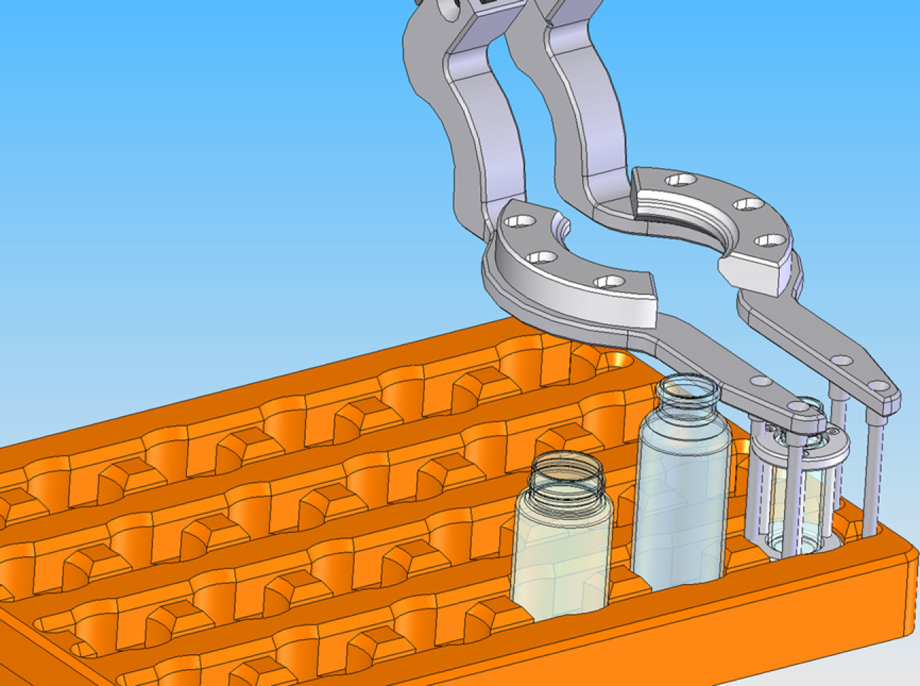
To release the robot from holding a vessel during multimode activity, a station was designed that held the vessel and automated the movement of the needle. The station was also designed to allow the needle to be cleaned between samples. A total of five vessel types were required to be processed in this system, ranging from 4-mL vials to 250-mL bottles. To transfer the entire contents to the evaporator, it was necessary to have the needle at the bottom, and to incline the vessel at an angle. With different thicknesses, heights, and diameters of glass, this was a real challenge to the designer, especially as variation in glass production processes is relatively high. The vessel holder was a major challenge, because once designed, it proved to be more difficult to fabricate than anticipate. Utilization of Rapid Fabrication technologies using a Viper
6
Stereolithography (SLA) machine allowed the design to be checked first. This took three iterations before the design was deemed to be final. The final arrangement meant that the vessels were staggered height-wise and so the use of a simple pneumatic cylinder to drive the needle up and down was becoming more of a challenge. This problem had been partly solved during the initial design phase, to take up the variation of glass thickness at the bottom of the vessel. To take up this difference, the needle was mounted between springs with a compliance of over 50 mm. The needle was then simply mounted on the pneumatic cylinder via a bracket (Fig. 4).
Computer Aided Design of wash station (A) cross-section (B) isometric.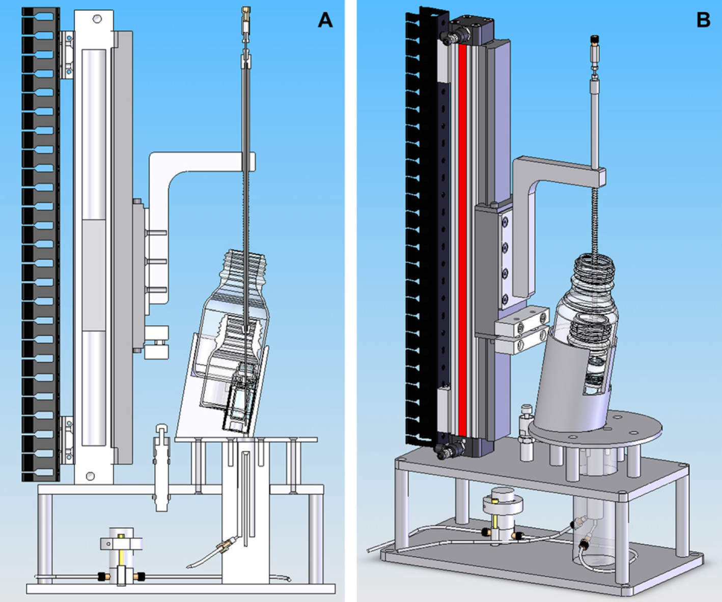
Stäubli Robot
The project team had extensive experience with a range of industrial robots but, for this project, opted for the Stäubli 7 TX60 robot over other robots due to the superior mechanical and integration aspects. The repeatability of the Stäubli is ±0.02 mm, which is better than the Kawasaki FS02N (±0.03 mm). The reliability of Stäubli robots is high, requiring only an annual check and 20,000-h preventative maintenance schedule. The Kawasaki FS02N, for example, has a 5000-h maintenance schedule. The Stäubli teach pendent allowed rapid teaching of locations and testing of programs as the speed can be controlled in real time. The teach pendent on the Kawasaki FS02N did not allow real-time speed control, which was a real issue during testing. The TX60 robot, with vertical attachment of connectors, was selected due to its payload, reach, and also being single phase 240 V rather than three phase 415 V. Having a vertical attachment enabled the cables to be hidden under the bench and allowed the full range of bench space to be used. The I/O capabilities allowed all the system safety circuits, sensors, relays, switches, valves etc. to be wired and controlled directly in robot movement programs. Although the team had extensive experience in programing robots, for this project, Aitken Scientific 8 was used to write the pick and place robot programs to more effectively integrate into the main controlling software application, Evaporate Express.
Vessels
A total of five vessel types were required to be used in the system. This had been reduced from a larger number to simplify the automation. The two large vessels were standard Schott Duran 100- and 250-mL bottles, both having the same cap size. The vial capacities were 30, 20, and 4 mL. The 30- and 20-mL vials were the same diameter, but of different heights. The smallest vessel, a 4-mL vial, was placed in a cradle that was designed to be of the same physical dimensions as the 20-mL vial, but would not interfere with the evaporation process (Fig. 5).
Vessel types.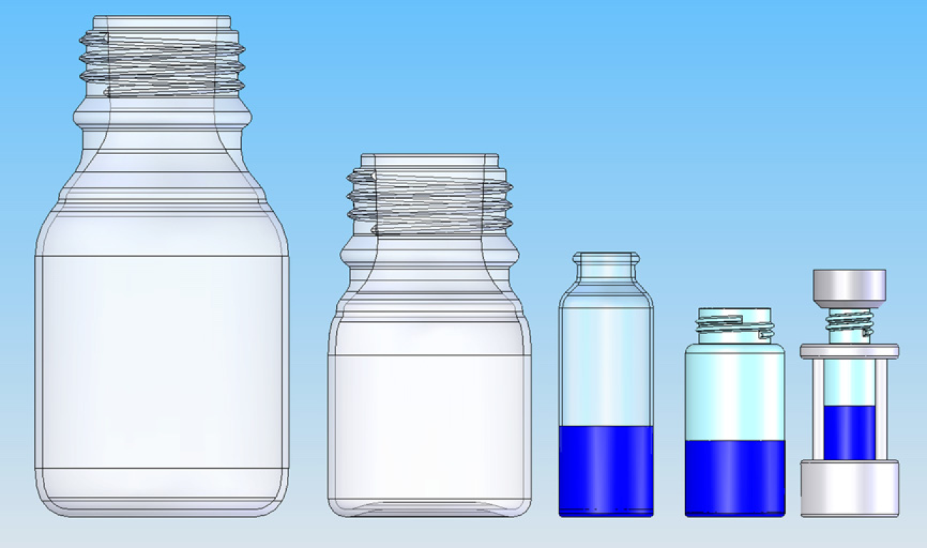
Cradle
The 4-mL vial could not be used directly on the V-10 because a locator at the bottom would have been required, which was different for the other vials. So either a mechanism to change this mid-run would be required or another solution needed to be found. An adapter was also required on the top of the vial to enable it to fit on the V-10. Because changing the bottom locator at run time would have been very difficult, a cradle was designed to hold the smallest vial. As the V-10 heated the vial using a hot air blower, it was important to design the cradle so that the heat transfer to the vial was not altered. In addition, the vial/cradle spun at high speed, so the rotational velocity was a significant design factor to consider. Thus, the cradle was designed to be the same diameter as the larger vials, and not taller than the 30-mL vial with the adapter at the top. In addition, a simple cost-effective construction method was required. A number of Viper SLA prototypes were made, of Bluestone resin, to test the principle before the design was finalized and manufactured in aluminum. The Bluestone prototypes withstood the physical trials during testing, but were deemed to be too fragile for long-term use.
Multiple Gripper Design
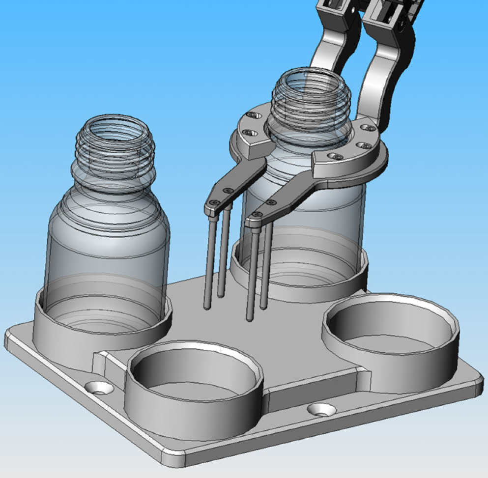
The gripper assembly consisted of fabricated stainless steel fingers mounted on a Schunk 9 MPG50 pneumatic two-finger parallel actuator. A Schunk OPR-81 anticollision avoidance device was mounted between the gripper and the robot flange to protect equipment from damage in the event of a collision. The gripper had to be designed to pick up all five vessel types. To simplify the design and remove the need to use tool changing technology, the design carefully considered the vessels and the locations, which they would occupy. Having the gripper mounted at an angle allowed access to all the locations in the system in a compact configuration. Without the angle, it was not possible to have a high-density configuration. The V-10 required an adapter on the smallest vessel, and so by careful design it was possible to reduce the complexity of the gripper. The choice of pick-up locations then allowed both bottle sizes to be picked up in the same way. Thus, the gripper was able to pick up all five vessel types using two locations, one at the front and one in the middle.
The gripper design also had to take into account the restrictions on the V-10, and needed to be designed in conjunction with the injector and the racks to work (Figs. 6–8).
Computer Aided Design of gripper. Computer Aided Design of gripper showing vial-picking location. Computer Aided Design of gripper showing bottle-picking location.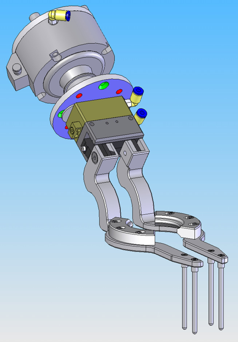
Benches
The design of the benches was a significant factor to ensure both reuse in the future, and in order that the system could be easily moved. The system was modularized such that the robot was mounted on its own bench with controller below, with identical benches either side allowing future flexibility. Having separate benches allowed each bench to be moved through a single door opening. The bench was also designed to be used in conjunction with a standard GSK enclosure. Special jacking castors were used on each bench, which have a combined castor and leveling foot. The benches were constructed using ITEM
10
extruded aluminum profile, which was easy to construct, flexible for future change, and allowed a range of components to be fixed to it. The same bench and mounting plate can be used to fix other industrial robots such as the Kawasaki FS02N robot (Fig. 9).
Computer Aided Design of robot bench.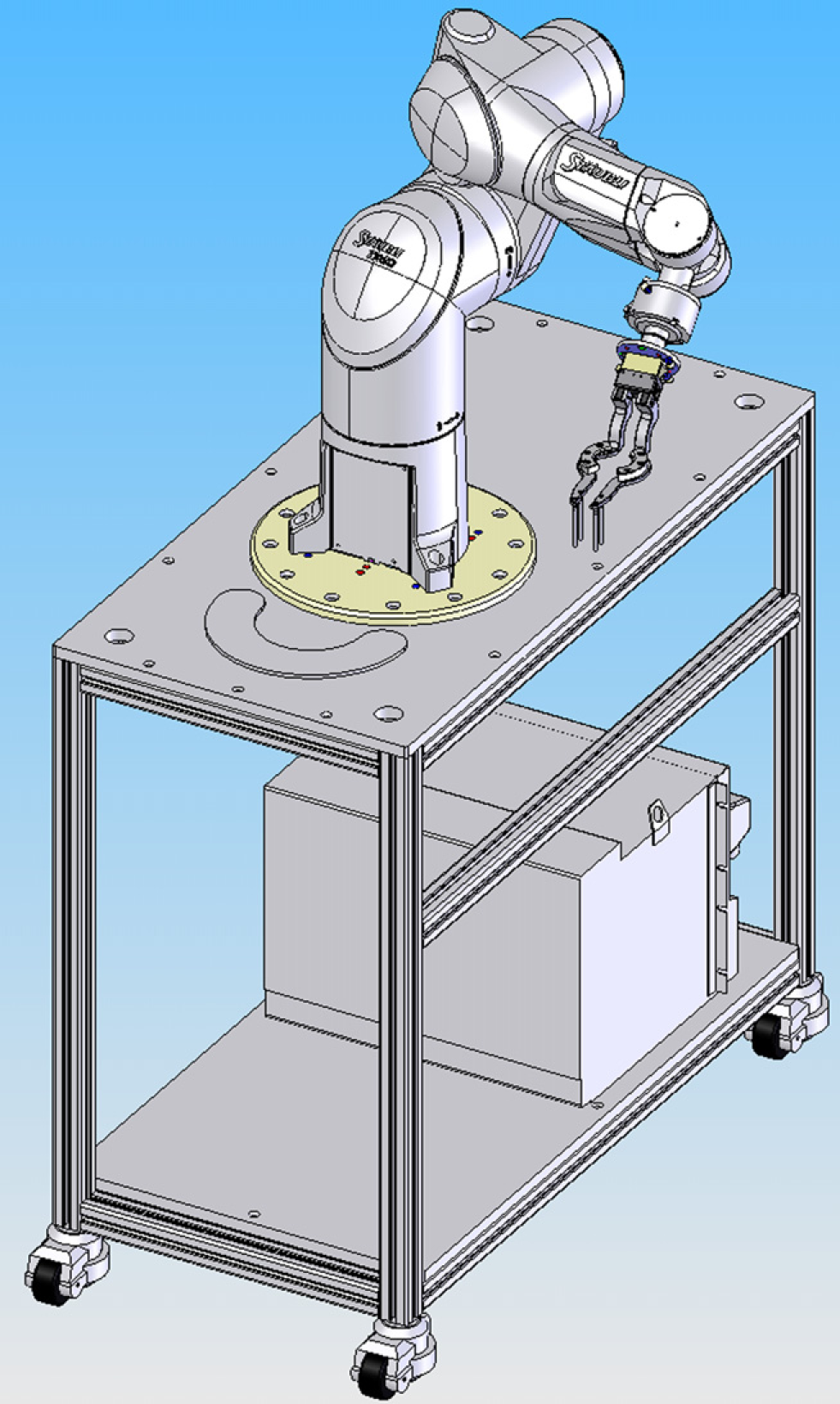
Engineering
It was the philosophy of the project team to use off-the-shelf OEM products whenever possible. The fabrication of custom-designed racks, grippers, and the injector station etc. was done using local precision engineering firms under a competitive tendering process. To prevent corrosion, anodized aluminum or stainless steel was used throughout, as the system was deployed in a laboratory environment.
Evaporate Express Software
The core software package used in the prototype 2 was retained, but converted to a database driven system with an improved user interface. A driver for the Stäubli robot replaced the Kawasaki driver.
The software was divided into two main components: a set of robot control programs which ran on the Stäubli robot controller and the controlling software application, Evaporate Express, installed on a standard PC running Microsoft Windows XP.
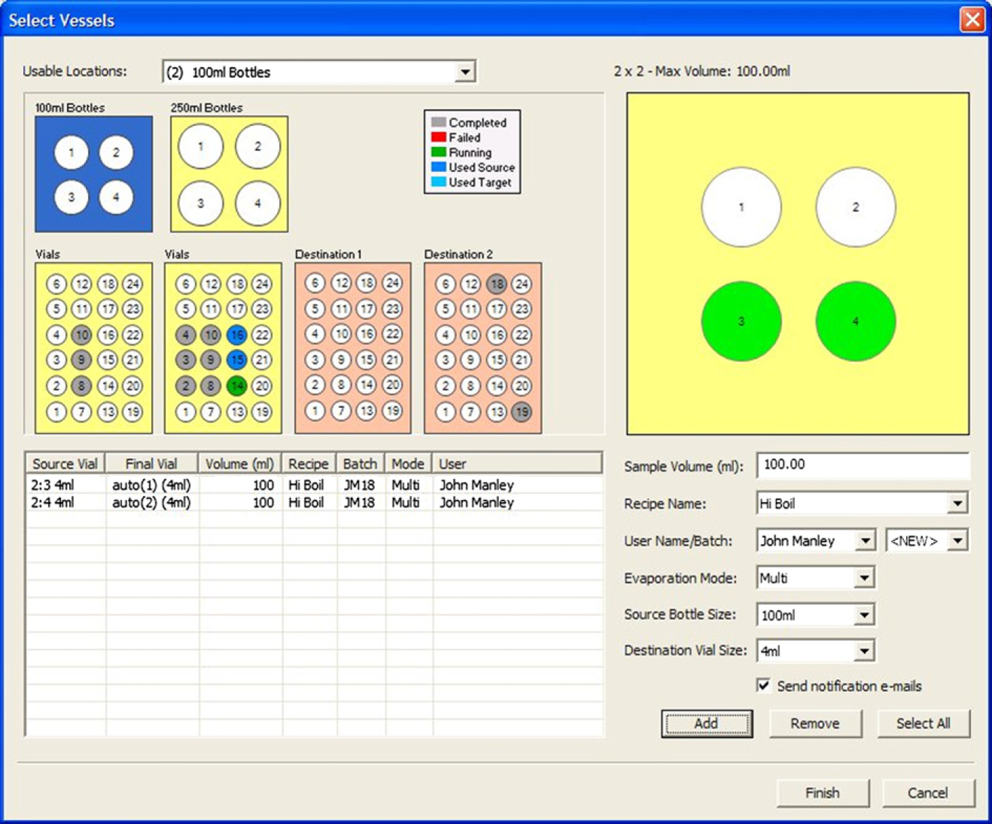
Evaporate Express, a commercial database-driven application written by Aitken Scientific, 8 provided a graphical user interface allowing users to select the samples they want to process. Information about the samples was stored in a Microsoft Access database, which was used by the system at run time. As samples were processed by the system, their status was updated and stored in the database. In the event of a power failure, the state of the system and the sample list were preserved allowing automatic recovery without user intervention into the database.
The software contained a number of “plug-in” modules for controlling the various hardware components. The modules, in the form of component object model (COM) objects, were used to control the V-10 evaporator and the Stäubli robot. These modules were not specifically written for Evaporate Express and could be used in other applications. They were also compatible with Aitken Scientific's A-S Automate automation software package.
The evaporator module controlled the V-10 using RS232; a serial command interface was provided by the manufacturer, Biotage. A COM object was written providing a subset of these serial commands, for such operations as raising and lowering the lift, starting a protocol, etc.
The interface of the evaporator control includes the following methods:
LoadVial()—Raise the cradle and seal the vial against the evaporation head.
Evaporate()—Start an evaporation. The recipe or method and vial type are set through appropriate properties.
Stop()—Stop an evaporation in a controlled manner.
CleanNeedle()—Start the process for cleaning the aspiration needle of the injector station.
The properties exposed by the control include:
Recipe—Select the recipe or method to use when running the evaporation process.
VialType—Select the vial type to use when running the evaporation process.
SampleVolume—Set the sample volume to use when conducting a multisample evaporation.
Mode—Set the evaporation mode of the evaporator.
Status—Return the current status of the evaporator.
The robot module controlled the Stäubli robot and took the form of a client, which communicates with a server running on the robot's controller. The server, written by Stäubli, handled requests from the client module and made a number of functions available. These included running custom-written robot programs to carry out specific tasks (such as “move a vessel from a rack to the evaporator”), retrieving status information relating to the robot, and controlling the robot's digital IO lines. Communication between the client and server was achieved using a transport control protocol/internet protocol (TCP/IP) network connection. Both the evaporator and robot modules were designed with a generic interface allowing other similar devices to be supported in the future without the need to modify the core software application.
The robot module included the following methods in its interface:
StartProgram()—Start a named program on the robot controller.
StopProgram()—Stop the current robot control program.
SetParameter()—Set a parameter in the global parameter array accessible by a robot control program.
QueryStatus()—Return the current status of the robot controller.
The custom robot programs, written by Aitken Scientific, controlled the specific robot manipulations required to move vessels around the system.
There were four main robot programs:
RackToEvap—Pick up a vial from one of the racks and place it on the evaporator cradle.
EvapToRack—Retrieve a vial from the evaporator cradle and return it to its original position within a rack.
RackToSampler—Pick up a bottle or vial from one of the racks and place it on the injector station.
SamplerToRack—Retrieve a bottle or vial from the injector station and return it to its original position within a rack.
In addition, a recovery program was written to ensure that the robot could safely return to a predefined “safe” position from any location in the event of an emergency stop (Figs. 10–12).
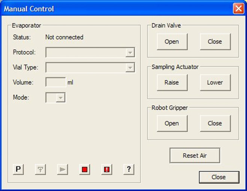
EvaporateExpress software Top Level Screen. EvaporateExpress software—sample addition screen. EvaporateExpress software—manual control screen.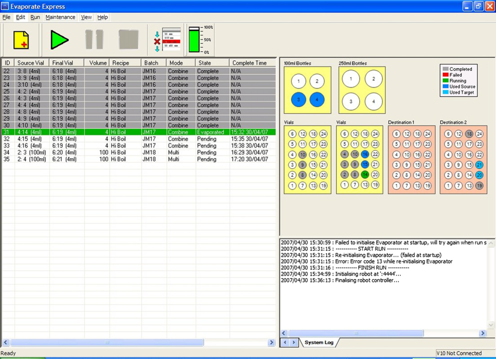
Server Application
Stäubli developed a specific driver (GSK Command Server) for this application, which ran on the TX60 robot. This server was designed to listen and respond to messages provided by the client (Evaporate Express).
The server was designed to respond to the client quickly while still managing the status of emergency stops, doors, and robot arm. To achieve the fastest possible response to a message received from the client, two separate tasks were required, one task to listen for new messages and the other to monitor the state of the safety circuits and robot activity.
The “SERVER” task was an endless loop with no waits or traps or delays, whose job was to listen to the communication port. Any message received was rejected or executed depending on the system activity and safety status, which was controlled by the “STATUS” task. This task controlled any programs necessary for communication between the client and the server and visa versa. The only messages generated in this task were the immediate responses to incoming messages from the client. Asynchronous messages were sent to the client via the “SERVER” task, but these were originally generated in the “STATUS” or user programs (robot activities).
The commands supported by the “SERVER” task include:
Run Program (G)—execute a named robot program resident on the robot controller.
Suspend Program (H)—suspend execution of the current robot program.
Resume Program (C)—resume a suspended robot program.
Set Program Parameters (W)—set the data stored in the program parameters array on the robot controller. The program parameters array was a global array, which robot programs could read to access variable data.
Set Digital Output (OD)—set the digital outputs on the robot controller to the specified states.
Get Digital Input (ID)—read the states of the digital inputs on the robot controller.
Commands were sent to the server by the client using a TCP/IP socket. If a command required any parameters, these would be appended to the command and separated by commas. For example, the “Run Program” command required two parameters: the name of the program to run and a timeout value (the maximum time the program should take to execute). The command to run a program called “Rack-ToSampler” would take the form:
“G, RackToSampler, 120”. On receipt of this command, the server immediately issued a response to indicate the success or failure of the command, which the client dealt with in an appropriate manner.
The “STATUS” task was another endless loop, which monitored the state of any user programs or motion in progress and also monitored system e-stop and door circuits. This task also controlled the user program timeout mechanism.
Any state changes were relayed to the “SERVER” asynchronously. The status of all system elements was checked within each iteration of the loop.
The “GSK Command Server” had the functionality required to interface with Evaporate Express allowing simple yet comprehensive remote control of the Stäubli TX60/CS8C system.
The figure below shows the various states of a user program as managed by the “STATUS” task and controlled by Evaporate Express via the “SERVER” task (Fig. 13).
GSK Command Server state diagram.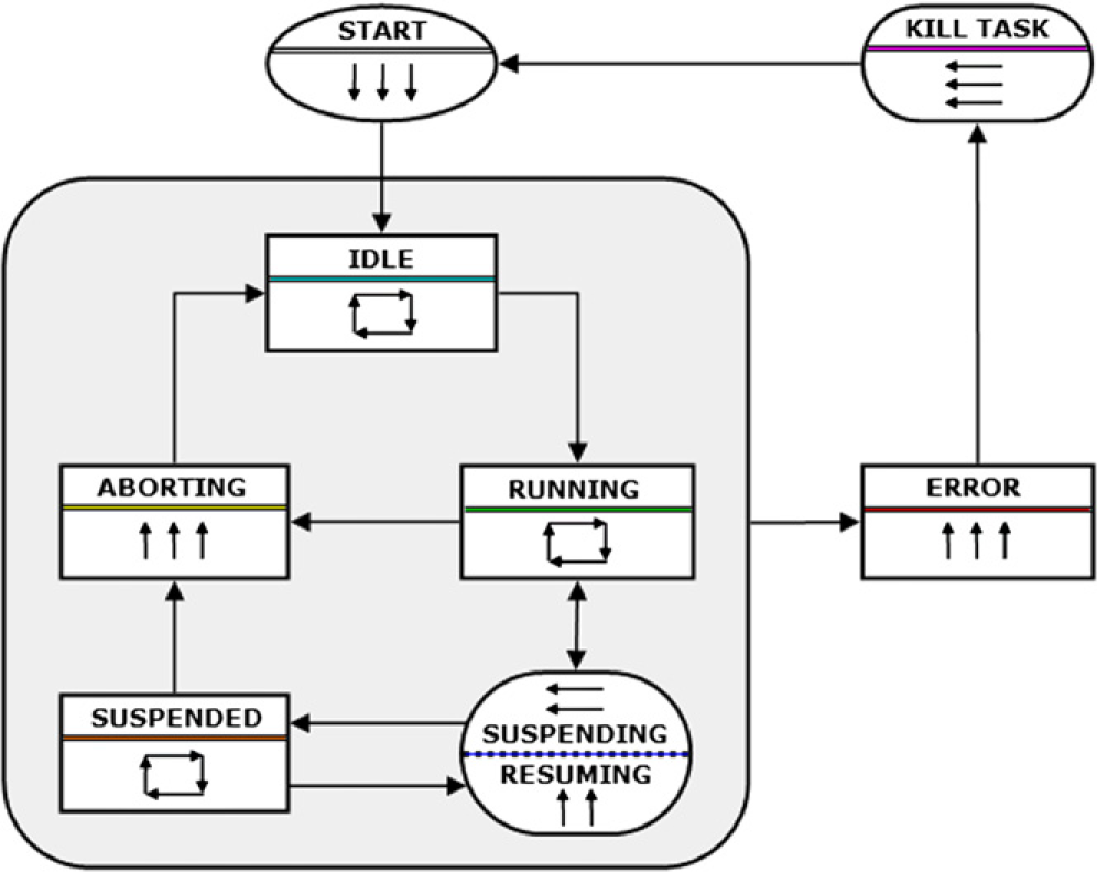
Safety
To comply with conformité Européene (CE) and internal GSK safety standards, a number of safety aspects had to be resolved during the design stage. The use of interlocks on the enclosure ensured that the robot and injector were disabled when the doors were opened. Even if the injector was moving when the enclosure door was opened, the pneumatic cylinder, and hence needle, stopped immediately. The software was written such that the robot moves were point-to-point, at a set speed, and the routes were well defined and tested. These programs were stored on the controller, so that the user never had to interact directly with the robot, only via the interface that controlled the entire system. Electrical circuits were fail-safe and wired directly into the robot safety circuits. E-stops were added to the system at both sides allowing rapid stopping in the event of an issue. In the event of an e-stop event, power failure or other event that halted the robot, the system software had a self-recovery mechanism that returned the robot to the safe position at slow speed, reversing the previous path. This was extensively tested in a range of scenarios.
On-Going Support
To maintain the system, support considerations were a major factor in the design process. The use of robust industrial components minimized the support burden, but added additional safety considerations. GSK has an internal support group dedicated to automation support. The project team worked with this group at key stages in the design to incorporate support considerations, and then provided them with full technical documentation, manuals, safety review, CE certification, and training after deployment. Support by external third parties was thus possible as all the necessary elements (documentation, training etc) were already in place.
Results
System Build
Once the final design had been approved and procurement had started, it took 4 months to build and test the system. The lead time for the robot was the major factor, and system testing of the software could not begin until the physical robot was in place. All the components arrived at different times, but it was possible to build benches, write the software, and do unit testing before the robot arrived. The Stäubli robot was easy to install, with clear installation instructions, available before purchase, allowing design and fabrication of mounting plates, gripper design etc. before the robot arrived. Mounting the robot and getting it ready for testing took less than a day. Excellent support and training provided by Stäubli allowed the rapid integration in a matter of weeks.
Stäubli Robot Programing
The language used to control the robot was easy to learn, allowing pick and place control programs to be written quickly. However, the language also allowed high-complexity control, and integration with other systems, but required expert knowledge. Stäubli and Aitken Scientific provided this knowledge, allowing a control system to be written based on user requirements. A simple pick and place program that moves a vial from a rack to the V-10 is shown below. A series of move commands navigates the robot safely to the destination and moves the vial or bottle in combination with opening and closing the gripper. The basic “MOVEL” command requests the robot moves from its current position to the specified position (using x, y, z, rx, ry, rz Cartesian coordinates), in a straight line with a specified tool type (geometry and action), with movement description (speed, acceleration, deceleration, blending etc). Comments have been added before each command to explain their function.
The addition of checks, for example checking whether a cradle was already in the V-10 using the robot I/O, built on the basic program and made the language very powerful.
Upgrades
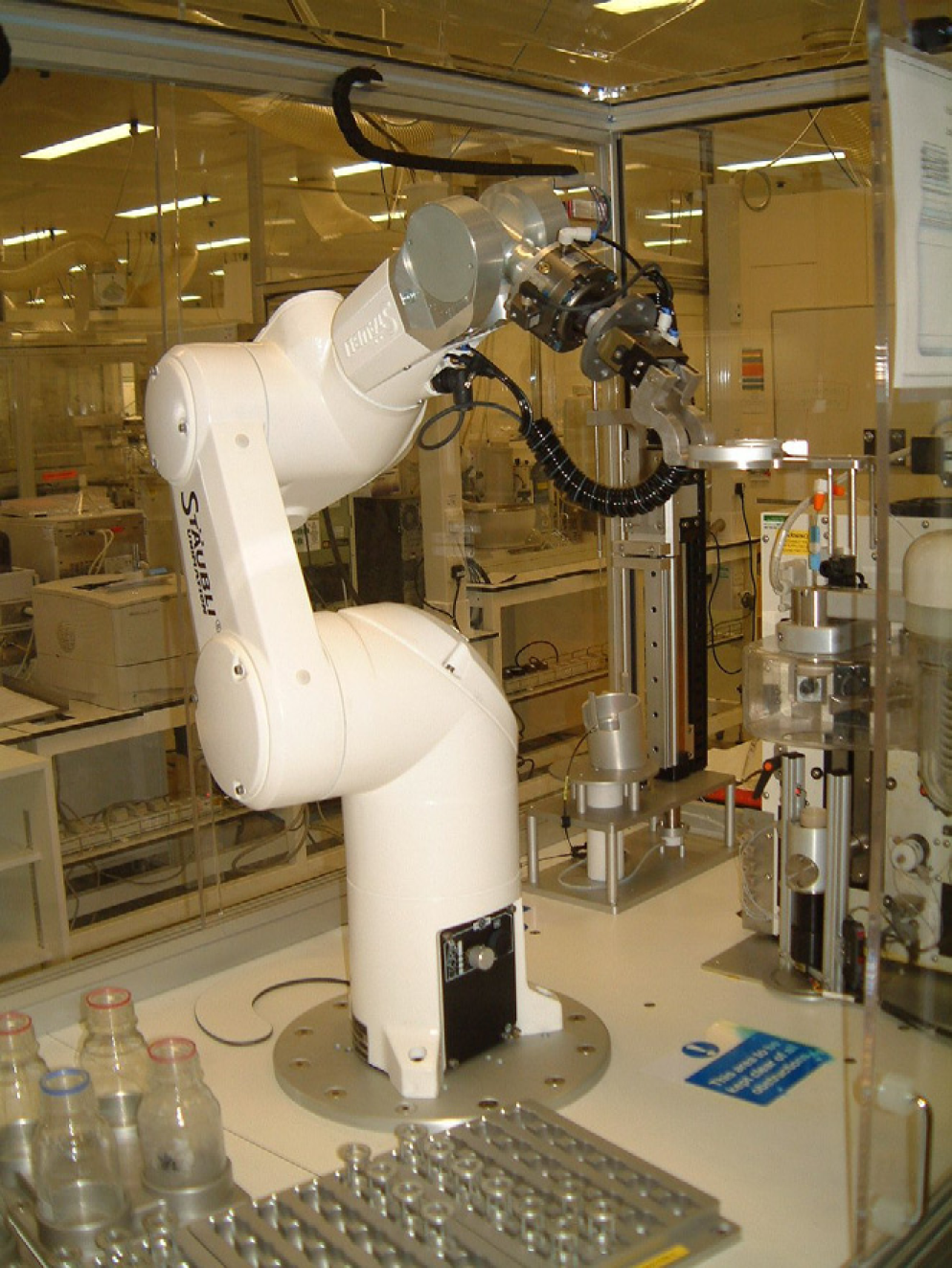
Software upgrades have been performed, and because the software was developed in a phased manner, additional features have been added. Installation and testing of new software versions were achieved within a few minutes, due to the modular approach used, and having full installation sets. Future changes, such as replacing the hardware could be done relatively quickly as the knowledge is in-house. Updating the CAD, procurement, build, software changes, and test would be required, but at a reduced effort level (Figs. 14 and 15).
Photo of deployed system. Close-up photo of robot, injector, V-10, and racks.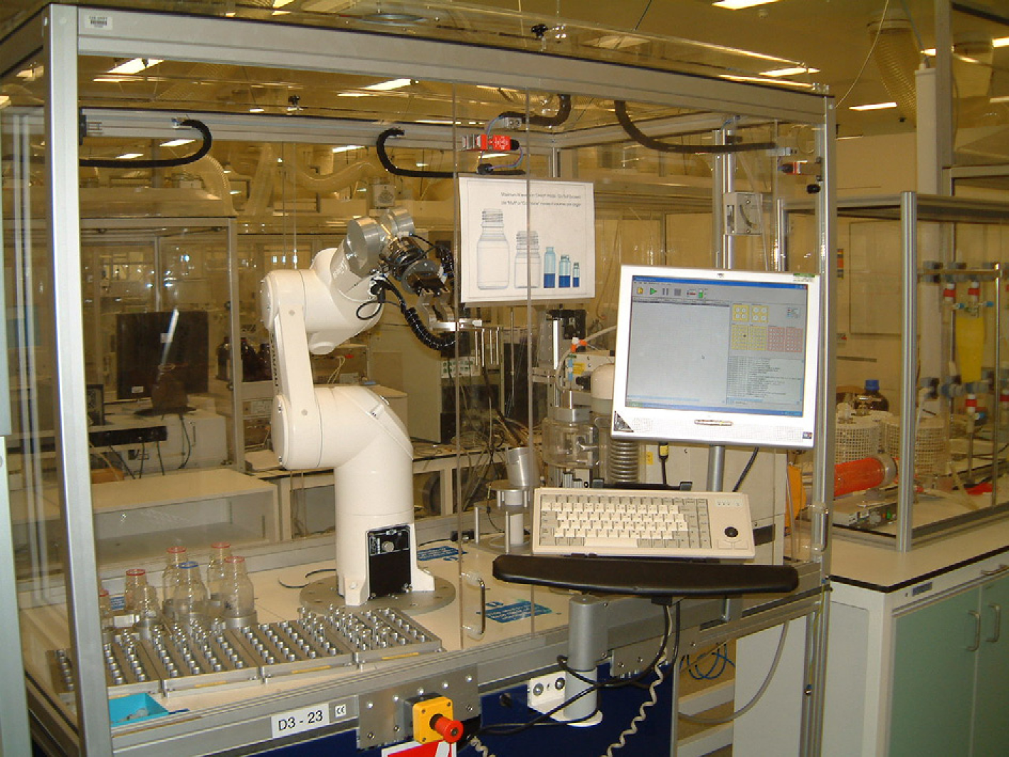
Operation
The system was designed to be open access and intuitive for the users with minimal training. In the months after deployment to a high throughput Chemistry laboratory of ~50 chemists, a large number of samples have been processed using the system, with no issues.
Evaporation times for the V-10 were significantly faster than for other evaporation techniques such as centrifugal or nitrogen blow-down, by factors of 20–40. Although the speed of individual samples was fast with the manual V-10 system, when multiple evaporations from multiple users were required the throughput and efficiency dropped rapidly. This was because once the system had dried its one sample, it remained idle until a user interacted with the system and unloaded it. This “hand-over” inefficiency has meant that the throughput of a manual system was limited to about 12 samples per day with an average of 4.
The automated system was designed to address this issue via the sample queuing ability of the software and the automated running of sequences of samples of the robotics. After the introduction of the automated system to the laboratory, throughput of the system has increased more than fourfold with an average of 20 samples per day. This was by no means its maximum capacity and usage is expected to increase as more users become familiar with the system and its benefits.
Conclusion
The use of modular approaches to the design of automated systems allows quicker, cost-effective deployment of solutions, and future reuse of components as processes change. In-house development, using CAD, also allows quicker development, and enables changes to be made more effectively. The system enabled time saving, and increased efficiency, of solvent evaporation for chemists.