Abstract
As a step toward high-throughput bioprocess development, we present design, fabrication, and characterization of polymer based microbioreactors integrated with automated sensors and actuators. The devices are realized, in increasing levels of complexity, in poly(dimethylsiloxane) and poly(methyl methacrylate) by micromachining and multilayer thermal compression bonding procedures. Online optical measurements for optical density, pH, and dissolved oxygen are integrated. Active mixing is made possible by a miniature magnetic stir bar. Plug-in-and-flow microfluidic connectors and fabricated polymer micro-optical lenses/connectors are integrated in the microbioreactors for fast set up and easy operation. Application examples demonstrate the feasibility of culturing microbial cells, specifically Escherichia coli, in 150 μL-volume bioreactors in batch, continuous, and fed-batch operations. (JALA 2007;12:143–51)
Introduction
Conventional microbial cell cultivation techniques have lagged behind array-based automated tools for discovery and genetic manipulation of biological systems. Bioprocess developments for microbial cultivation and optimization are typically performed in expensive, mechanically complex, and labor intensive, stirredtank bioreactors. Bench scale, stirredtank bioreactors, with typical volumes of between 0.5 and 10 L are instrumented with effective control of temperature, pH, and dissolved oxygen (DO) levels and yield valuable physiological and metabolic data. However, the relatively small number of experiments that can be performed limits optimization of growth conditions and metabolic studies. Bench scale, stirredtank reactor technology has been addressing these challenges by reducing volume and increasing the number of reactors operating in parallel. However, throughput remains limited by the mechanical complexity of setting up and performing experiments–processes such as assembly, cleaning, and calibration of sensors scale with the number of bioreactors. Thus, there is a need for systems that enable rapid testing, optimization, and bioprocess developments in low volume, parallel investigations with setup and run-time efforts that remain nearly independent of the number of bioreactors. The SIXFORS benchtop device by Infors AG (Bottmingen, Switzerland) has six fermentors operating in parallel. Another recent development, Cellstation bioreactors by Fluorometrix Corp. (Stow, MA) allow 12 miniature stirredtank bioreactors to be operated in parallel. However, the throughput using these devices is still limited.
Disposable, parallel-operated microbioreactors with small volumes of cultures and integrated real-time measurements have been proposed as a promising solution for high-throughput bioprocessing. An early microbioreactor was developed by Walther et al.1–3 as a 3 mL continuous bioreactor with integrated biomass, pH, and temperature microelectronic sensors for yeast cell cultivation in space. It was a self-sustained system with medium flow rate measured by a microsensor and controlled by a piezo-electric silicon membrane pump. pH was monitored by an ion-selective field effect transistor (ISFET) sensor 2 and manipulated by coulometric generation of hydroxyl ions at a titanium electrode. The system was aerated through gas-permeable cylindrical silicone tubes and mixing was done by a magnetic stir bar. Maharbiz et al.4, 5 integrated microtiter plate wells with silicon monitoring technology to realize 250 μL microbioreactor arrays with ISFET sensors on a commercial printed circuit board. For aeration, oxygen was generated in the reactor by hydrolysis of water. The microscale device reported by Lamping et al. 6 was a scaled-down version of conventional stirredtank bioreactors machined in Plexiglas and outfitted with air spargers and a stirring baffle.
Optical sensors are typically noninvasive and can be integrated into the design. Electrochemical sensors for oxygen, used on the macroscale, are generally not suitable for microsystems because they consume oxygen that otherwise would be available to the cell culture. Rao and coworkers7–10 pioneered optical sensing for measurements of optical density (OD) (related to cell density), pH, and DO for microbial batch cultures in 2 mL cuvettes, which demonstrated the feasibility of using optical sensors in microbioreactors to reduce mechanical complexity and enhance throughput. Puskeiler et al. 11 reported a parallel operation of 48 magnetically mixed milliliter scale bioreactors with integrated OD and pH real-time measurements and automation of fed-batch operation and pH control. These studies in miniaturization and parallelization of micro-bioreactors, as well as the commercial Cellstation (Fluorometrix Corp., Stow, MA) and Sim-Cell (BioProcessors, Woburn, MA) microbioreactor platforms underscore the potential of this technology in development of bioprocesses.
Our microbioreactors are based on the membrane-aerated microbioreactor previously reported by Zanzotto et al.
12
In this microbioreactor a thin membrane of poly(dimethylsiloxane) (PDMS), a highly gas-permeable polymer material, serves as the aeration membrane for cell metabolism. The membrane also defines the gas–liquid interface to provide a sterile, single-phase microbioreactor. With the integration of polymer-fabrication technologies, magnetic active mixing, temperature control, surface modification, and continuous fluidic system individual microbioreactors have been demonstrated for batch
13
and continuous culture
14
fermentations of
One important issue in high-throughput studies of bioprocesses is the parallel operation of microbial fermentations in disposable microbioreactors. Replacing the reactors requires a well-defined interface of the microbioreactor to external fluid handling, optical measurements, and electronic instruments. In this work, plug-in-and-flow microfluidic connectors and microfabricated polymer optical lenses and fiber connectors are integrated in the microbioreactor. The disposable microbioreactor, realized in poly(methyl methacrylate) (PMMA) and PDMS by a multilayer thermal-bonding procedure, automatically aligns with external fluidic and optical components, which addresses the need for rapid set up and ease of operation.
Microbioreactor configurations
The early generation of microbioreactor (Fig. 1A) was designed for batch cultivation of microbial cells. The reactor consisted of two PDMS layers (L2 and L3) sandwiched in between two PMMA layers (L1 and L4 in Fig. 1A). The bottom PMMA layer, made by using a computer-numerical-controlled (CNC) milling machine with dimensional accuracy of 12 μm, included the microbioreactor chamber (150 μL volume) and three connecting channels (M), which are used for inoculation and replenishment of water.
(A) Microbioreactor device used in batch cell cultivation. (B) Device used in pH-control and fed-batch cell cultivation. Microchannels were used for water- (P1), base- (P2), and acid-feeding (P3), inoculation (P4), and waste exit (P5) purposes, respectively. (C) Thermally bonded PMMA device used in continuous cell cultivation. Microfluidic channels allow for water-replenishment (P1), inoculation (P2), and waste exit (P3), and cell outflow (D) before and during chemostat experiments. (D) Cross-section of an integrated microbioreactor. L1–L5, thermally bonded PMMA layers; F PMMA cork used for mechanical assembly of the aeration membrane; H silicone O-ring for sealing; I optical fiber fixed by F; J grid for holding the PDMS membrane above the reactor chamber; K magnetic mixer in the center of reactor chamber; L recesses in PMMA for accommodating alignment pins P; M microfluidic channels; N small silicone O-rings for fluidic interconnections; O pH and DO fluorescent sensors; P PDMS alignment pins on optical plugs; S optical sensors.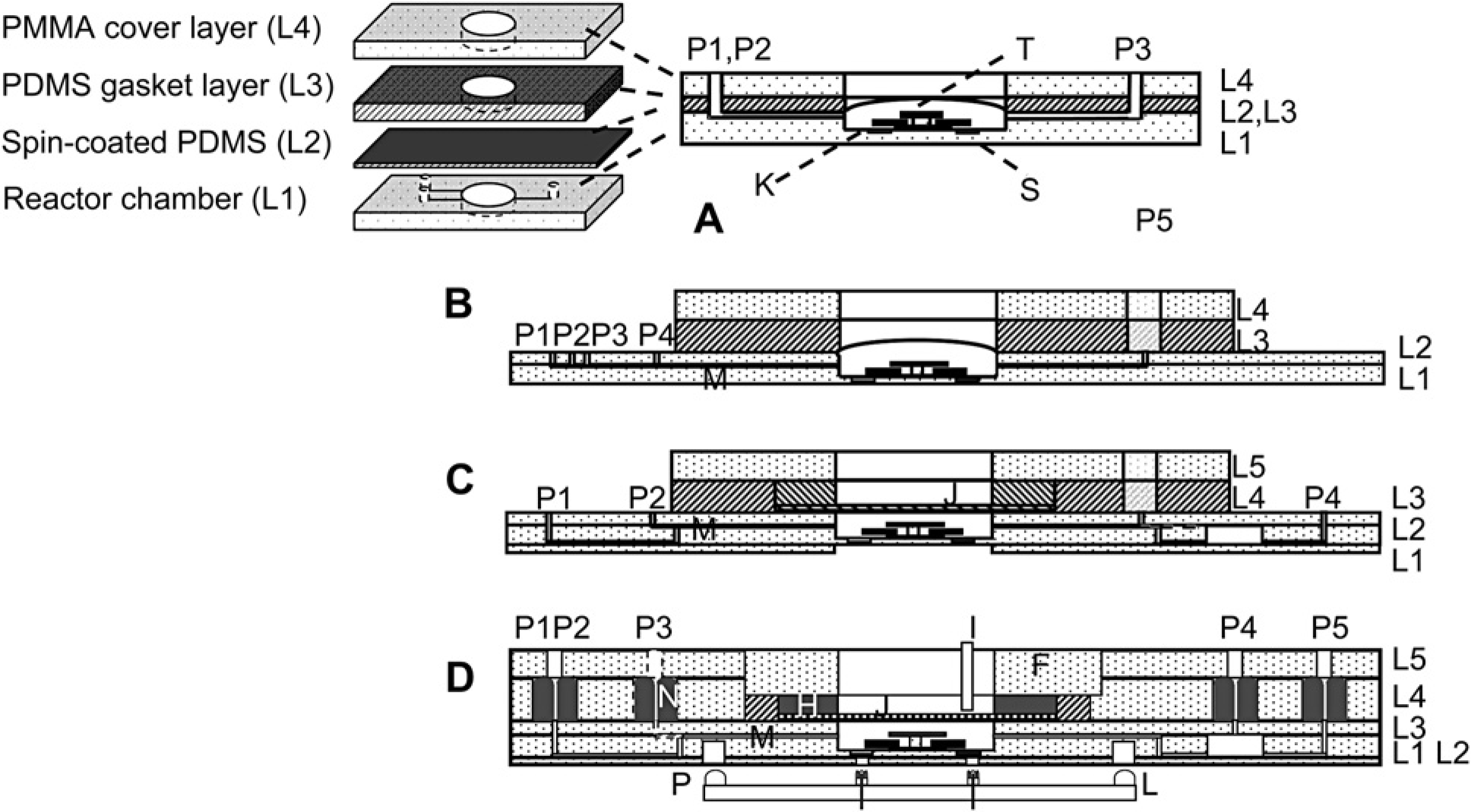
Two recesses (S, diameter 2 mm, depth 250 μm) at the bottom of the bioreactor chamber accommodated DO and pH fluorescence lifetime sensors (DO sensor foil PSt3, and pH sensor solution HP2A, PreSens–Precision Sensing GmbH, Regensburg, Germany). Details of the fluorescence lifetime measurements are summarized elsewhere.12, 15 In the center of the device, a reactor chamber was fabricated in layers L1 to have a cylindrical geometry with a diameter of 10 mm and a depth of 1 mm. A ring-shape magnetic stir bar (K) with 6 mm arm length and 0.5 mm thickness (custom-made by Engineered Concepts, Vestavia Hills, AL) was held by a PMMA post (T) and was used for active mixing in the reactor chamber. The mixing efficiency in the microbioreactor chamber was evaluated through experiments and computational fluid dynamic simulations. 13
A thin layer (~100 μm in thickness) of spin-coated PDMS (L2; mixing ratio of silicone to curing agent was 10:1. Sylgard 184, Dow Corning Corp., Midland, MI, USA) covered the reactor chamber and served as the aeration membrane. PDMS was spin-coated at a speed of 1200 rpm for 25 s and then baked at 70 °C for 2 h for curing. The PDMS membrane bulged upward as a result of a positive pressure in the microbioreactor chamber to reach a reactor volume of 150 μL. To facilitate device assembly, hermetical sealing, and connection of microfluidic channels (M), this PDMS layer was held by a 5-mm thick PDMS gasket layer (L3). A top PMMA layer was used to provide a rigid support for the mechanical assembly. Three ports connected the microbioreactor chamber with external setup via microchannels (M) and served for the purposes of inoculation (P1), waste replenishment (P2), waste outflow (P3; used during inoculation).
The microbioreactors were adapted to more complex fermentation processes, for example, chemostat and fed-batch, by adding additional features. The device in Figure 1B was used for pH control and fed-batch operations. 17 The reactor chamber was made of two PMMA layers (L1 and L2 in Fig. 1B; Goodfellow Corp., PA) thermally bonded at a temperature of 140 °C for 90 min in a homemade press. In this press, a pair of Belleville disc springs (diameter: 119.0 mm; thickness: 1.25 mm; height: 2.80 mm, MSC Industry Supply Co., Inc., New York) maintained a constant load of 0.12 MPa.
The major feature for this microbioreactor is the ability of base-, acid-, and glucose-additions during fermentation, closed-loop controlled by external microvalves (INKX0514300A, The Lee Co., Westbrook, CT) and control circuits (IECX0501350A, The Lee Co.). Microfluidic channels (M), machined in layer L1 and sealed by layer L2, were used for water- (P1), base- (P2), and acid-feeding (P3), inoculation (P4), and waste outflow (P5; used during inoculation) purposes, respectively.
Figure 1C was used for continuous culture of bacterial cells to obtain chemostat data (data shown in Fig. 1B). 14 The microbioreactor chamber (10 mm in diameter and 2 mm in depth, with a total volume of 150 μL) and four connecting channels were fabricated in three thermally bonded bottom PMMA layers (layers L1 through L3; Goodfellow Corp.). The thin PDMS aeration membrane was covered with an additional layer of stainless steel grid (B-PMX-062, Small Parts Inc., Miami, FL) fixed by a homemade PDMS O-ring to provide a perforated membrane structure and to avoid membrane bulging. Microfluidic channels (M) were machined in both sides of layer L2 and sealed by layers L1 and L3. These microfluidic channels allow for medium addition (P1), inoculation (P2), waste exit (P3, used during inoculation), and cell outflow (P4) before and during chemostat experiments. An external syringe pump (PhD2000, Harvard Apparatus, Holliston, MA) connected to P1 provided a steady media feeding during continuous culture experiments.
The latest microbioreactors (Figs. 1D and 2) improve interfacing of the microbioreactor to the external instruments (fluidic handling, optical monitoring, electronics, and computer control) without modifying the biological function of previous designs. The devices are made of five thermally bonded PMMA layers. Precise thermal bonding of PMMA layers with different glass transition (TG) temperatures was performed in a mechanical press in two steps. First, the three bottom layers (layers L1 through L3; Goodfellow Corp.) were bonded at a temperature of 140 °C for 90 min. Second, the resulting composite was bonded with the top two layers (A and B; MSC Industrial Supply) at a lower temperature of 120 °C for 60 min. The reactor chamber, fabricated in layers L2 and L3, had the same shape and size as in the previous designs. On the top of reactor chamber, the thin PDMS aeration layer was held by a 3-mm thick PDMS gasket layer (part G in Fig. 2, 20 mm inner diameter, 25 mm outer diameter, fabricated in a polycarbonate mold) to facilitate device assembly and sealing.
(A) Overview of individual parts for the microbioreactor shown in Figure 1D. (B) Top view photograph of assembled and bonded microbioreactor.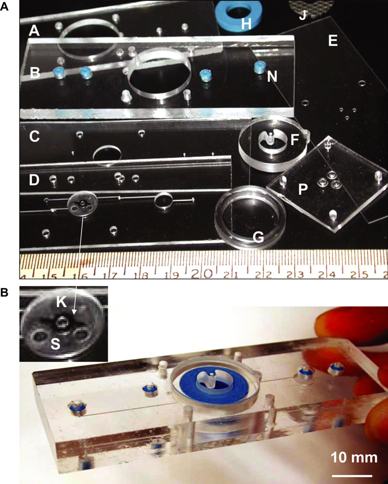
A PMMA “cork” (Fig. 1D) (F) with an outer diameter slightly larger (13 μm larger in diameter) than the inner diameter of PMMA housing frame (machined in A and B) created a seal by compressing the PDMS (G) and a Sylastic RTV silicone elastomer (Dow Corning) O-ring (H, inner diameter of 10 mm, outer diameter of 20 mm, and height of 3 mm made with a polycarbonate mold). A small hole in the cork also aligned the optical fiber (I) for the OD transmission measurements. This cork allowed the microbioreactor to be cleaned and reused by replacing PDMS membranes after experiments, a useful feature in exploratory studies, but too labor intensive for parallel investigations. Therefore, in the disposable bioreactor version the PDMS membrane was permanently fixed between PMMA layers after thermal bonding and the stabilizing grid structure was molded in the PMMA layer B. Similar to previous microbioreactors (Fig. 1A–C), the fluorescence lifetime sensors are integrated at the bottom of device chamber (Fig. 1D) for pH and DO online measurements. Indentations beneath these sensors (L1 and L2) now couple optical fibers (O) to external fluorescence detectors and lifetime measurements for better alignment.
The fluidic interface between a microbioreactor and external fluidic units was composed of custom-made elastomer O-rings (N) integrated in the PMMA device (Fig. 1D). They allowed aseptic self-sealing, “plug-in-and-run” functionality, between external fluid handling and internal microfluidic channels for inoculation, reagent feed, sampling, and waste outflow. The O-rings were cast in Sylastic RTV silicone elastomer (Dow Corning) from stainless steel molds with an outer diameter of 4.2 mm, an inner diameter of 0.2 mm, and a depth of 4.6 mm. The stainless steel molds were fabricated by using a 2-mm diameter ball-head endmill (MSC Industrial Supply) at a high rotation speed of 8000 rpm and subsequent electro-polishing to obtain a smooth surface. The O-rings were cured at room temperature for more than 12 h to obtain a Young's modulus of 4.5 MPa. They were then embedded into housings machined in a thick PMMA layer (L4, Fig. 1B) and were fixed by a cover PMMA layer (A) when the two layers were thermally bonded. The housing for each O-ring had a slightly smaller diameter (4.1 mm) and depth (4.45 mm) so that the O-ring was compressed and the center hole sealed; 1.5-mm diameter through-holes in the covering PMMA layer corresponded to the center positions of the O-rings. When stainless steel tubes (12 mm long, 23 gages, Small Parts, Inc.) were inserted, the elastomer O-ring expanded and making a fluidic connection. The process was reversible and the seal leak tight up to pressures of ~0.6 MPa.
Experimental Setup and Optical Interface
DO, pH, and OD600 nm were measured by the optical sensing methods already described by Zanzotto et al. 12 so only a brief summary is given. The experimental setup for a single fermentation run is illustrated in Figure 3. Fermentations were carried out by placing the microbioreactor in an aluminum chamber maintained at 37 °C by flowing heated water through the chamber base. Bifurcated optical fibers (custom-made by RoMack Fiber Optics, Williamsburg, VA) led into the chamber from both the top and the bottom and connected to LEDs and photodetectors (PDA-55, Thorlabs, Newton, NJ) to perform the optical measurements. Biomass was followed by OD600 nm data obtained from a transmission measurement using an orange LED (Epitex L600-10 V, 600 nm, Kyoto, Japan). The bifurcated branch provided a reference signal to compensate for any intensity fluctuations of the orange LED. Both DO and pH were measured using phase modulation lifetime fluorimetry. The DO and pH sensors were excited with a blue-green LED (505 nm, NSPE590S, Nichia America Corporation, Mountville, PA) and a blue LED (465 nm, NSPB500S, Nichia), respectively. Excitation band pass filters (Omega Optical XF1016 and XF1014) and emission long pass filters (Omega Optical XF 3016 and XF 3018) separated the respective excitation and emission signals to minimize cross-excitation. Data switches (8037, Electro Standard Laboratories, Cranston, RI) multiplexed the output signal and the input signal of the function generator (33220A, Agilent Technologies, Palo Alto, CA) and the lock-in amplifier (SR 830, Stanford Research Systems, Sunnyvale, CA). LabVIEW software (National Instruments Corp., Austin, TX) enabled automated and real-time measurement of the parameters.
Illustration of the measurement setup for microbioreactor. Dashed lines indicate optical fibers, and solid lines show electronic wires and fluid tubes.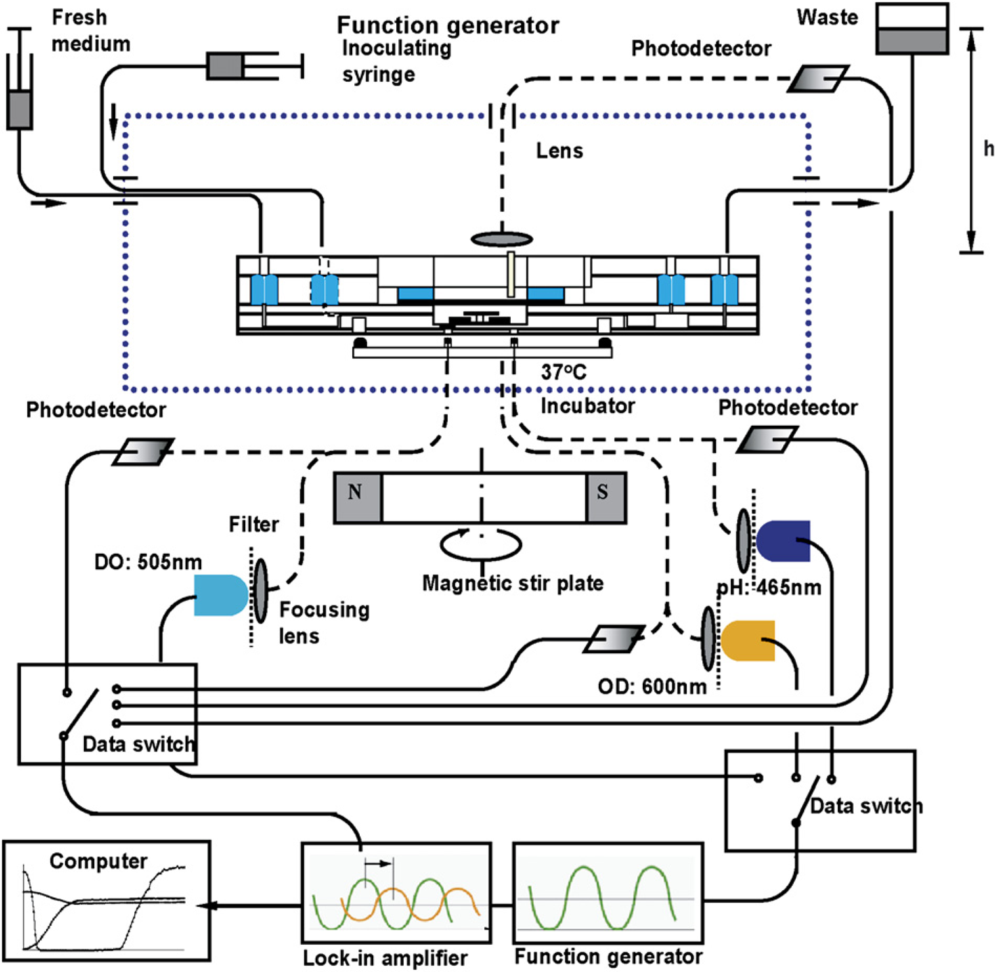
Based on this design, a multiplexed system for parallel operation of four microbioreactors was reported by Szita et al. 15 In this system, a stepper motor carried an optical bracket to scan over the microbioreactors in stop-and-go sequences executed by computer-controlled algorithms. The process parameters were measured and recorded for each reactor using lifetime fluorescence and absorbance methods in a sequential mode. The number of experiments was increased for the same external instruments, such as the lock-in amplifier and function generator. However, the scanning/reading speed for the individual microbioreactor reactor ultimately limited the possible number of parallel experiments.
As an alternative, a self-aligning strategy was developed for the optical interface between external measurement setup and disposable fluorescence sensors inside of the micro-bioreactor. Integrated microlens and optical connectors (Fig. 4A) were molded out of PDMS in an aluminum mold fabricated by conventional milling using a 2-mm diameter ball-head endmill (MSC) and mechanically polished using a shaft grinder kit (Dremel, MSC), cotton swabs, and polishing paste (Novus Plastic Polish, MSC). The aluminum mold was composed of two parts. The bottom part of the mold ensured the replication of the negative shape of the microlens and four pillars aligning the plug to the microbioreactor. The upper part contained 10-mm long columns aligned concentrically to the lenses for casting the PDMS plug housing, guiding, and fixing the optical fibers.
(A) Picture of microlens and alignment ring around the microlens (top). Cross-section showing three microlenses assembled with optical fibers. P represents the PDMS alignment pins. (B) Focusing by a PDMS microlens. Light intensities at different lateral location from a cleaved fiber (green line) and an optical microlens (blue line). Smooth curves from two-dimensional ray tracing model. (C) Photograph of optical microlenses assembled with optical fiber housing. Fibers shown are 0.25 mm in diameter. Epoxy and external mechanical support are not shown.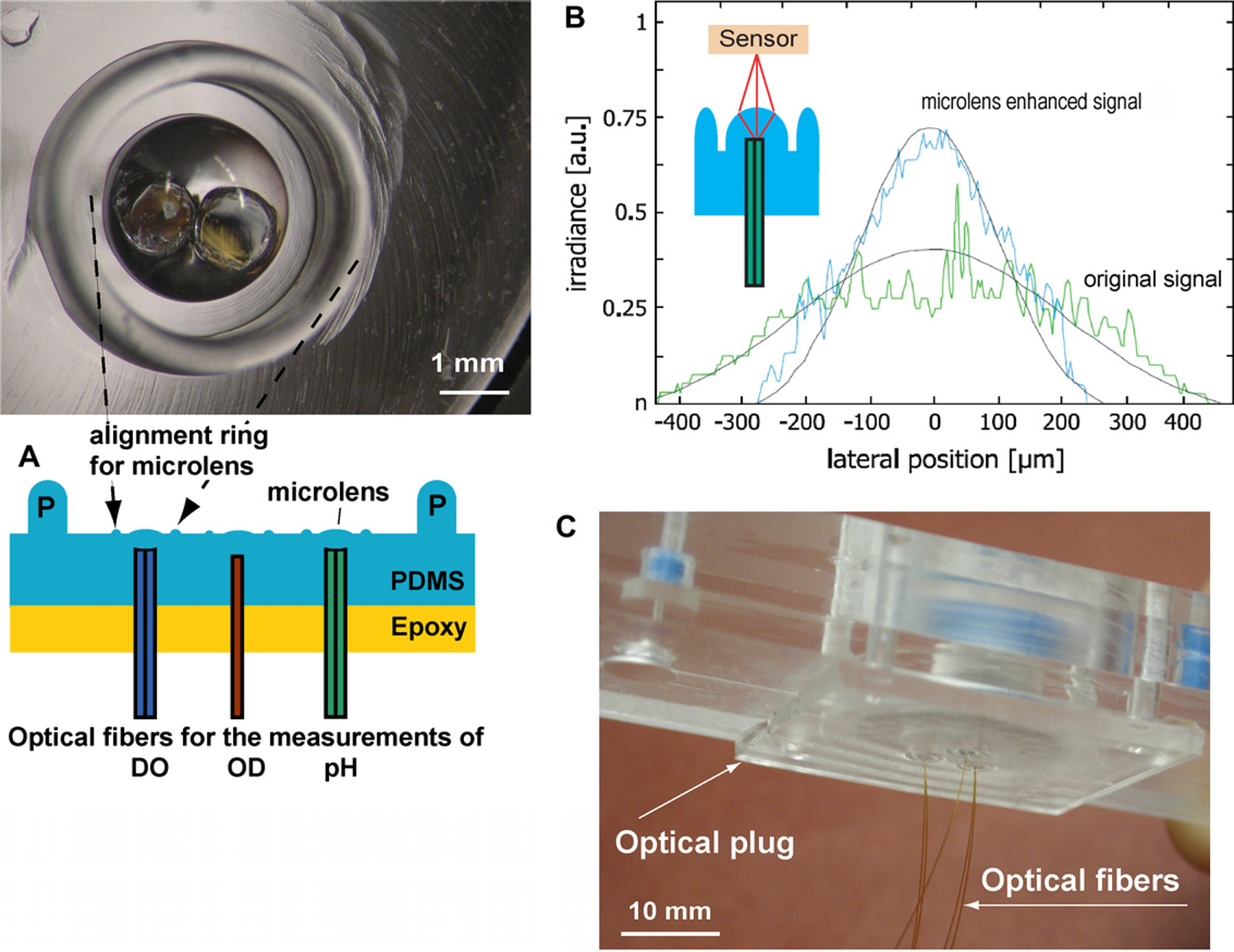
For pH or DO measurements two optical fibers (plastic fibers 1 mm and 0.6 mm in diameter, BFL 37-1000 from Thorlabs, Inc. and FVA500550590 from Polymicro Technology LLC, Phoenix, AZ, respectively) were housed in the correspondent cavity fabricated in the PDMS plug (Fig. 4A). The fibers were secured by PDMS added after fiber insertion and held in place by a support. The PDMS was cured and finally epoxy was cast on top to give mechanical stability to the plug. These fibers replaced the expensive, customer-made bifurcated optical fibers used in earlier work.12, 15 At the same fabrication process, one fiber (0.6 mm in diameter, Polymicro Technology LLC) was fixed in the center of plug for the OD reading. The optical fibers were placed at specific axial distances from the hemispherical outer surface shape to focus on the optical sensors in the bioreactor. Different focal points were designed in the optical plug for the different DO, pH, and OD measurements. Calibration and optimization of positions for pH and DO reading maximized the intensity of light from the fluorescent sensor to improve the signal-to-noise ratio of measurements. For the OD measurement, the design aimed to obtain parallel light transmission through the reactor and good detection on the other side of the device. To guide the design, a two-dimensional model was developed using ray optics theory. Images of the light distribution showed good agreement with the model (Fig. 4B). The measurements show a maximum light intensity from the plugs, which is 50% higher than from the cleaved optical fibers and is significantly more focused with respect to lateral distribution of light. Even in presence of slight misalignments away from the center, focusing by the microlenses made coupling of light more efficient compared to butt-end coupling techniques.
Another important feature of the connector, the alignment ring around the microlens (cf. Fig. 4A) was fabricated with a size comparable to the size of the cavity beneath the microbioreactor (1.6 mm from the center, 1 mm high, and 0.4 mm wide). The mold was fabricated using a 0.4-mm diameter ball-head endmill, TR-2-0130-BN, Performance Micro Tool, Janesville, WI). The alignment ring helped positioning of optical fibers to optical sensors, protection microlens, and made setup procedures significantly easier and faster (Fig. 4C).
Biological Experiments in Microbioreactors
Applications of microbioreactors in batch,13–15 continuous culture,13–15 and fed-batch
17
operations have been demonstrated and are briefly summarized here. In the experiments shown in Figures 5–7,
E. coli FB21591 batch culture in LB medium containing 8 g/L100 μg/L kanamycin, and 0.1 mol/LMES (Fig. 1 Amicroreactors). Glucose feeding fed-batch cultivation of E. coli in LB medium containing 8 g/L 100 μg/L kanamycin, and 0.1 mol/L MES (Fig. 1B microreactors). Feeding medium contained 40 g/L glucose and the DO setpoint was 37% of air saturation level. Continuous cultivation of E. coli in microbioreactors (Fig. 1C microreactors). Feeding MOPS medium contained 2 g/L 100 μg/L kanamycin, and 0.1 mol/L MES.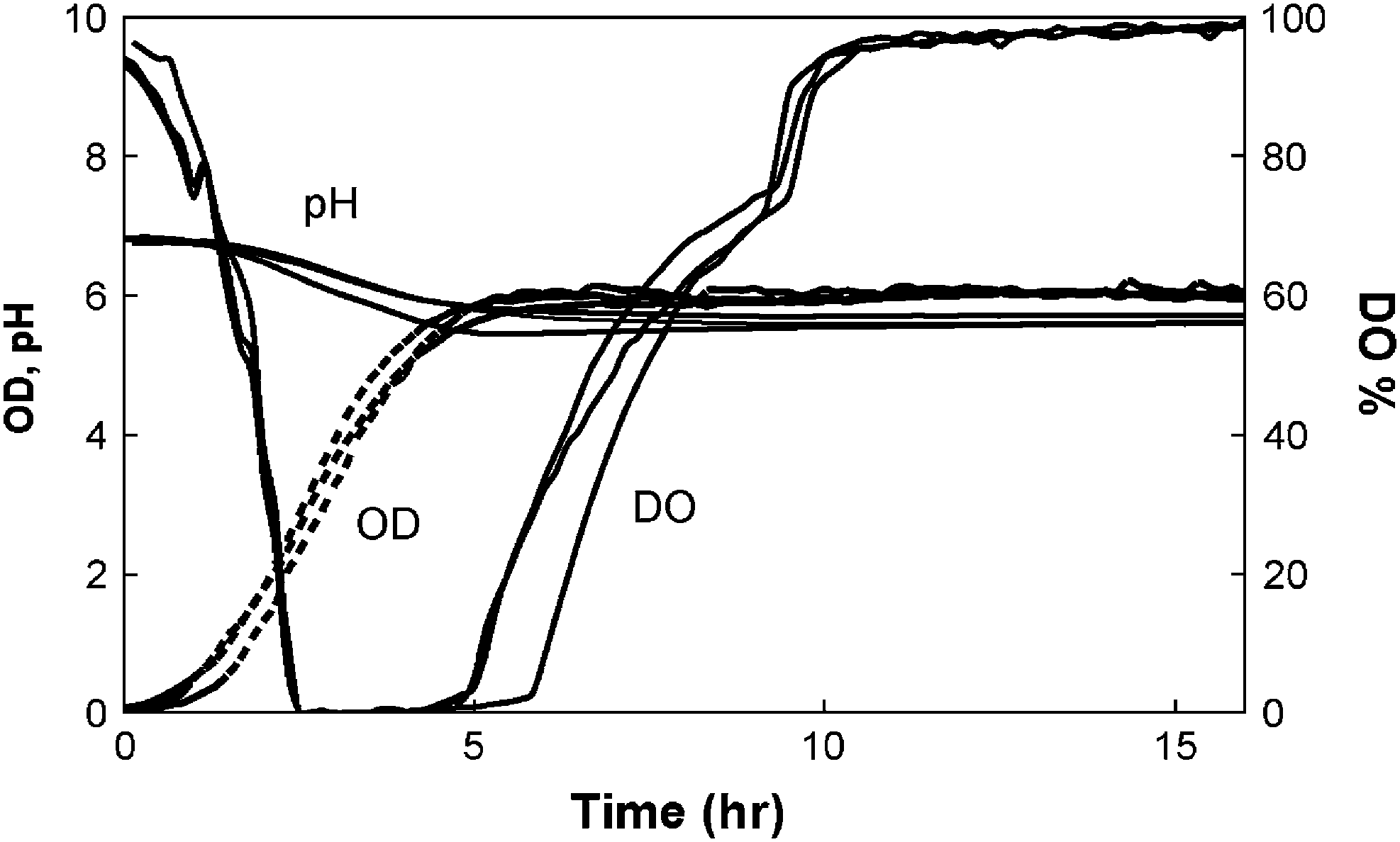
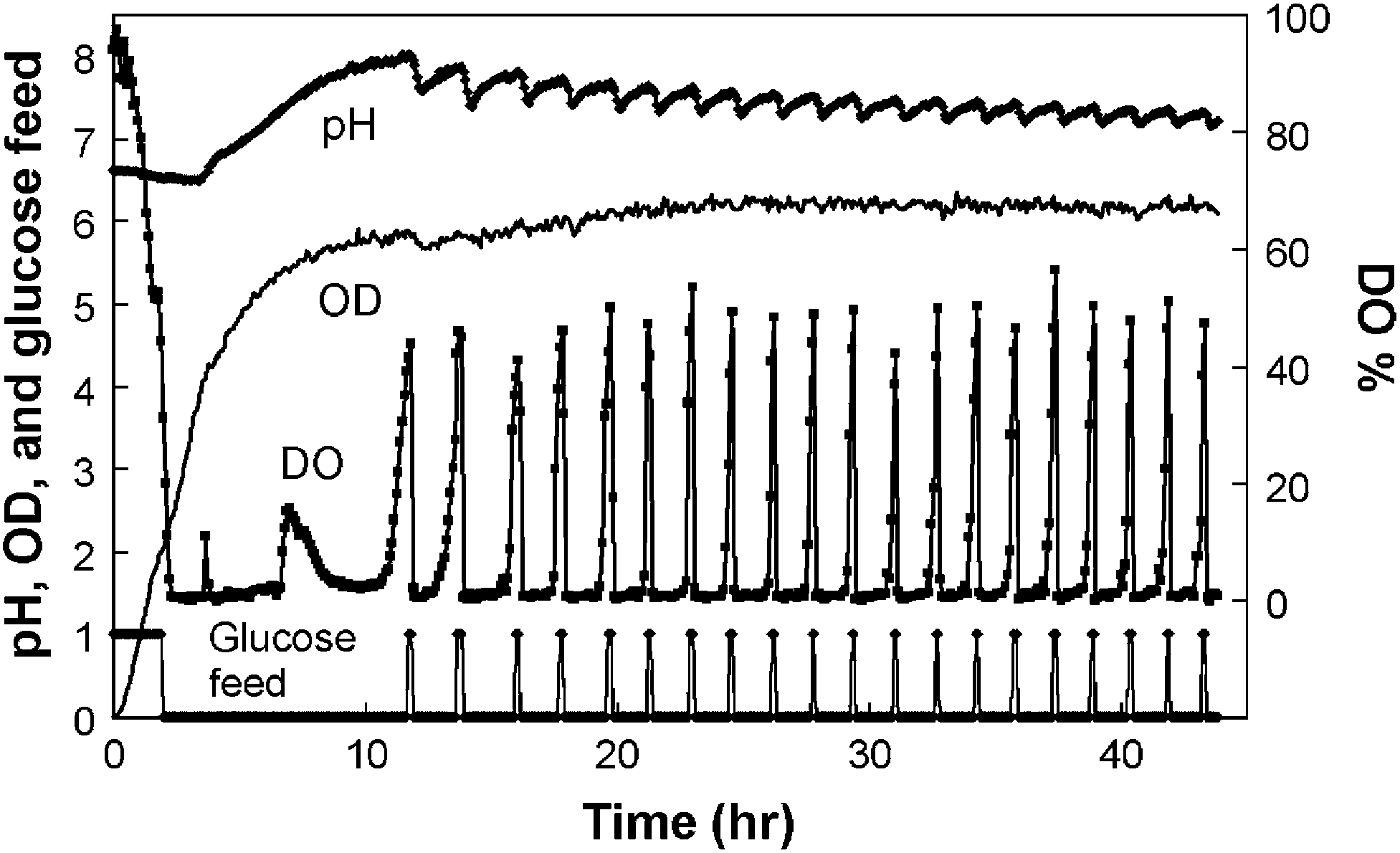
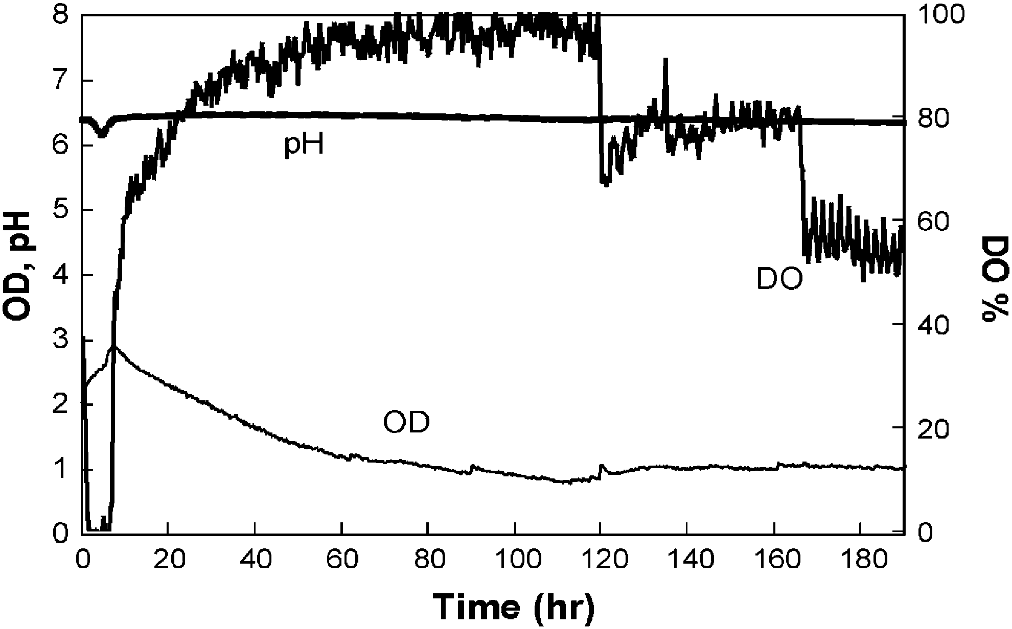
Figure 5 shows reproducible
In Figure 6, a fed-batch experiment
17
started with the inoculum of
Figure 7 demonstrates the continuous culture
14
of
Conclusions
The goal of this study was to develop a practical, user-friendly bench-scale system to meet the needs of high-throughput bioprocess developments. The microbioreactor platform was designed as two components: disposable microbioreactors and a fixed housing device, which includes expensive optical components and instruments. Having previously demonstrated a multiplexed microbioreactor platform for microbial cell cultivation, 15 the present efforts are focused on the packaging, integration, and optimization of the microbioreactor to make it compatible with the high-throughput approach.
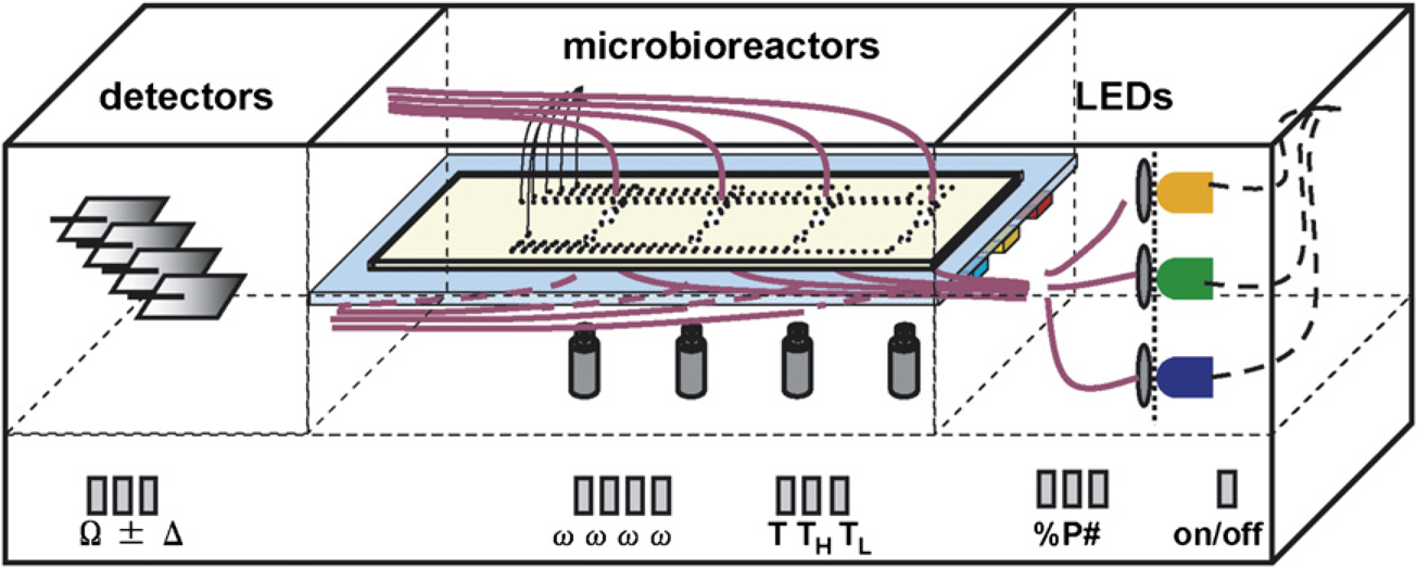
Microfluidic connectors and PDMS microlens optical connectors were designed and integrated to serve as “plug-in-and-run” interfaces with external fluidic and optical instruments, respectively. These connectors not only streamline and simplify the setup procedures for multiple microbioreactors, but also help to increase the accuracy and reproducibility in measurements. The bioreactor chips consist of multiple thermally bonded PMMA layers with an embedded PDMS aeration membrane. The bioreactor design, with its aeration membrane, magnetic stirring, local temperature control, and fluorescent sensors, provides flexibility for different bioprocessing applications, including batch, fed-batch, and continuous operations. With the plug-in-and-run interface, the disposable bioreactor could be implemented in a next generation multiplexed reactor platform that avoids the moving parts associated with the previous design. 15 Such a parallel system could be envisioned to consist of a platform containing fluid handling, optical measurements, data acquisition, and power supplies (Fig. 8). The disposable microbioreactor would plug into this platform as the only replacement part. Previous experience with individual or multiplexed microbioreactors has shown that experiments with ~100 μL volumes reproduce growth kinetics as well as gene expression profiles observed in 0.5 L bench-scale systems.18, 19 Thus, microreactor technology promises to enable faster, less labor intensive bioprocess development, with much reduced reagent usage and waste generation.
Schematic of multiplexed bioreactor system for high-throughput bioprocess developments. Microbioreactors are plugged in to platform in the middle chamber. Solid lines denote optical fibers and thick dashed lines indicate electronic wiring. Signal conditioning electronics, control units, and power supplies are in the bottom portion.