
Abstract
We report holographic polymer-dispersed liquid crystal (H-PDLC) gratings driven by surface acoustic waves (SAWs). Our experiments show that upon applying SAWs, the H-PDLC grating exhibited switchable properties: The diffraction of the H-PDLC grating decreased, whereas the transmission increased. This acoustically switchable behavior is due to the acoustic streaming-induced realignment of liquid crystals as well as absorption-resulted thermal diffusion. Such SAW-driven H-PDLC gratings are potentially useful in many photonic applications, such as optical switches, spatial light modulators, and switchable add/drop filters.
Introduction
Holographic polymer-dispersed liquid crystals (H-PDLCs) 1 have been developed for a wide range of photonic applications.2–7 In an H-PDLC structure, liquid crystals (LCs) exist within polymeric matrices as periodically arranged micro/nano-droplets/channels. The optical properties of the entire H-PDLC structure can be effectively altered when one externally changes the orientation of LC molecules inside the droplets.8,9 In this regard, electrical and optical10–19 approaches have been extensively exploited to reorient the LC molecules. However, these two manipulation methods have their respective limitations. For example, electrically driven H-PDLCs demand a high electric field (10−20 V/µm) due to the high surface area to volume ratio of small LC droplets.20–22 This becomes problematic because the wholly organic nature of H-PDLC devices makes them vulnerable to high electric fields, thereby forestalling practical application. In addition, optically driven devices show a propensity for poor optical contrast. To overcome these limitations, researchers are still searching for other driving schemes to meet the requirements of excellent optical performance and low power consumption.
Beyond electrical and optical driving, LC molecules can also be acoustically reoriented. 23 LC realignment based on acoustic waves has already found valuable applications within the areas of imaging24–26 and medical diagnostics.27–29 Ozaki et al.30,31 used acoustic streaming to change the alignment of cholesteric LC molecules and demonstrate a lasing effect. Very recently, we have demonstrated a surface acoustic wave (SAW)–driven light shutter based on PDLCs. 32 The SAW-driven approach is energy efficient and free of contamination due to its unique properties. In this letter, we report SAW-driven H-PDLC gratings for switchable diffraction, which are potentially useful in many photonic applications, such as optical switches, spatial light modulators, and switchable add/drop filters.
Materials and Methods
Sample Preparation
In our experiment, SAWs were generated by an interdigital transducer (IDT) on a piezoelectric substrate of lithium niobate (LiNbO3). The detailed procedures for IDT fabrication can be found elsewhere.6,33–36 In brief, two respective layers of metals (Ti/Au, 5 nm/80 nm) were subsequently deposited on a photoresist-patterned LiNbO3 substrate. The IDTs were then released after a lift-off process. To form an H-PDLC grating, a drop of prepolymer/LC syrup was sandwiched between a glass slide and the LiNbO3 substrate and then subjected to light exposure to induce phase separation between the LCs and polymers using a conventional laser holography setup. In this setup, two collimated writing beams from an Ar+ laser (488 nm) intersected at an angle of ~20°. Each beam had a diameter of 2 cm and an intensity of ~10 mW/cm2. The exposure time was 2 min. After exposure, the samples were further cured for another 10 min under a UV lamp to ensure complete polymerization. The PDLC cell thickness was controlled to be 15 µm using polystyrene beads as spacers. The prepolymer/LC syrup consisted of 43.37 wt% monomer, dipentaerythritol penta-/hexa-acrylate (DPPHA); 6.62 wt% cross-linking monomer, N-vinylpyrrollidone (NVP); 0.84 wt% photoinitiator, Rose Bengal (RB); 0.92 wt% coinitiator, N-phenylglycine (NPG); and 48.25 wt% LC E7. The LC E7 has the ordinary refractive index of no = 1.52 and a birefringence of Δn = 0.22 (ne = 1.74) at room temperature. Its clearing point is 58 °C. At the isotropic state, it has a refractive index of niso ≈ (2no + ne)/3 = 1.59. The syrup was mechanically blended to form a homogeneous mixture at a temperature of 70 °C.
Experimental Setup
Figure 1 illustrates the structure of the SAW-driven H-PDLC grating. This grating is located between two parallel IDTs on the LiNbO3 substrate. The first IDT is employed for SAW generation, whereas the second is for SAW detection. A radio frequency (RF) signal is applied to one of the two IDTs to generate the SAW, which propagates along the surface of the piezoelectric substrate. By tuning the applied frequencies from the function generator and monitoring the frequency-dependent amplitude in voltage on an oscilloscope, an optimum resonant frequency can be selected as the driving frequency. At this working frequency, the diffraction properties of H-PDLC gratings will be investigated.
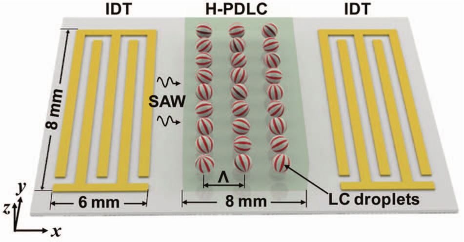
Schematic of the device structure of the surface acoustic wave (SAW)–driven holographic polymer-dispersed liquid crystal (H-PDLC) grating. The liquid crystal (LC) droplets are periodically arranged in the polymer matrix with droplet directions randomly aligned. The coordinate system is chosen to make the SAW propagate along the x-axis. The interdigital transducer (IDT) and H-PDLC have a working area of 6 × 8 mm2 and 8 × 8 mm2, respectively.
Results
H-PDLC Grating
Figure 2 shows the scanning electron microscopy (SEM) image of the H-PDLC grating with the LC cell de-capped and LC removed. It is clear that polymer-rich (lighter stripes) and LC-rich (darker stripes) lamellae alternate inside the grating structure. The two-beam interference at an angle of ~20° produced a 700-lines/mm H-PDLC grating with a period of 1.4 µm. Judging from the small holes, where the LC droplets reside, the size of most LC droplets is in the range of 50 to 300 nm in diameter.
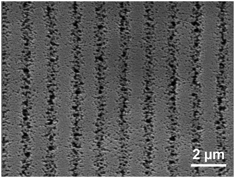
A scanning electron microscopy (SEM) image showing the morphologies of the holographic polymer-dispersed liquid crystal (H-PDLC) grating.
Acoustically Switchable Property
In our experiments, after the H-PDLC grating fabrication, we found the optimum working frequency of SAWs to be 18.76 MHz, which is in strong agreement with the calculation from the IDT period λ (λ = 200 µm, SAW velocity under the working situation c ≈ 3750 m/s, so the working frequency f = c/λ = 18.75 MHz). At this frequency, we investigated the intensity changes of the first-order diffraction of the H-PDLC grating. An He-Ne laser (633 nm) beam was normally incident on the sample. The diffracted intensity was collected by a power meter and fed into a computer. Figure 3 shows the first-order diffraction as a function of applied acoustic power. The diffraction intensity gradually decreases with the increase of the applied acoustic power. We attribute this change to the acoustic streaming-induced realignment of LC molecules as well as absorption-resulted thermal diffusion. When the propagating SAW encounters the H-PDLC grating, the acoustic wave attenuates while propagating due to the absorption and thermal conduction of the grating itself. The attenuated acoustic wave exerts a net force on the LC molecules inside the droplets through momentum conservation, which causes a steady flow known as acoustic streaming. 37 This acoustic streaming could lead to a vortical current inside the LC droplets that is responsible for realigning most of the LC molecules perpendicular to the substrate. 38 When most of the LC molecules align perpendicular to the substrate, the normally incident light sees only the ordinary refractive index of the LCs regardless of its polarization, which is nearly the same as the refractive index of the polymer matrix. As a result, the index modulation inside the grating disappears, as does the diffraction of the grating. In Figure 3 , the threshold switching power (the point of diffraction intensity change) is ~4 dBm, whereas the switching power (the point at which the diffraction intensity reaches a minimum) is ~24 dBm. The inset shows the captured intensity changes at the applied acoustic power of 0, 8, 16, and 24 dBm, respectively. It is evident that the diffraction intensity decreases while the transmission intensity increases. It is worth mentioning that with the increase of the acoustic power, the scattering of the H-PDLC grating also decreases along the normal incidence. The scattering originates from the LC droplet size distribution. In the H-PDLC grating, large LC droplets tend to scatter more light, producing a haze effect. When the acoustic field is applied on the sample, these large droplets will be the first to align due to their higher volume to surface area ratio, after which the haze will disappear, resulting in decreased scattering. When the acoustic power continues to increase, the smaller droplets start to align, and the index modulation further decreases. As a result, minimal scattering will be achieved. This is also confirmed from the inset of Figure 3 , where the light-scattering profile becomes smaller with the increase of acoustic power.
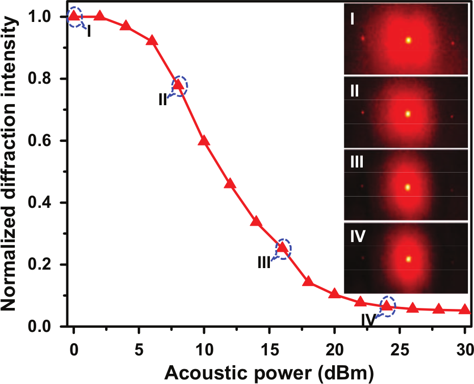
The switching dynamics of the first-order diffraction as a function of the acoustic power. The insets (I−IV) show the captured intensity changes at the applied acoustic powers of 0, 8, 16, and 24 dBm, respectively.
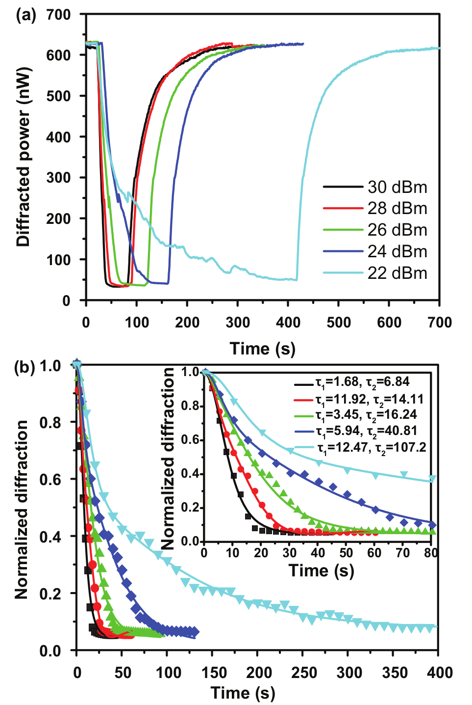
Furthermore, the switching dynamics of H-PDLC gratings were explored when the IDT was switched on and off. Figure 4a shows the diffraction changes during on and off processes under different acoustic power. One can see that the switching-on process strongly depends on the acoustic power. The higher the acoustic power applied, the faster the switching-on process occurs within the H-PDLC grating. At a certain acoustic power, the switching-on time and the contrast will finally saturate. From Figure 4a , it can be seen that the switching-off time keeps almost constant, since it is dependent only on the material properties of LCs. In our experiment, at the applied acoustic power of 30 dBm, the optimized switching-on and switching-off times were ~12 s and ~82 s, respectively; the achieved optical contrast, defined as maximum diffraction over minimum diffraction, was about 19.
(
Discussion
According to the report by Greanya et al., 39 the switching process of an LC sample by an acoustic wave usually has two relaxation modes with fast and slow time scales. For the H-PDLC grating, the experimental switching-on curves were also fitted using a double exponential function:
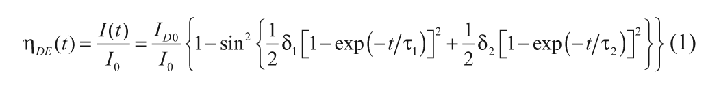
where δ i and τ i (i = 1, 2) are the fitting parameters, representing phase retardation and switching-on time. Figure 4b shows a detailed examination of the switching-on process. From Figure 4b , the double exponential function fits well with the dynamic switching behavior over the full range of switching-on time, which confirms that the switching process of the H-PDLC grating has two relaxation modes (slow and fast) with different time scales. We also note from the fitting of the graph that the time scales for switching on of relaxation modes τ 1 and τ 2 vary dramatically depending on the applied acoustic power. At higher acoustic power, both slow and fast relaxation modes have the same order of magnitude for switching-on time, whereas at lower acoustic power, the slow relaxation mode is one order slower than the fast relaxation mode.
In summary, we have demonstrated a SAW-driven H-PDLC grating based on the acoustic streaming-induced realignment of LC molecules as well as absorption-resulted thermal diffusion. Upon applying the SAW, the diffraction of the H-PDLC grating can be switched due to the refractive index matching between the polymer and LC lamella. This acoustically switchable property makes H-PDLC–based devices a promising prospect for photonic applications, including switches, modulators, and filters.
Footnotes
Acknowledgements
We thank Jason Scott for his helpful discussion.
Declaration of Conflicting Interests
The authors declared no potential conflicts of interest with respect to the research, authorship, and/or publication of this article.
Funding
The authors disclosed receipt of the following financial support for the research, authorship, and/or publication of this article: This research was supported by National Institutes of Health (Director’s New Innovator Award, 1DP2OD007209-01), the Air Force Office of Scientific Research, the National Science Foundation (NSF), and the Penn State Center for Nanoscale Science (MRSEC). Components of this work were conducted at the Penn State node of the NSF-funded National Nanotechnology Infrastructure Network.
References
Supplementary Material
Please find the following supplemental material available below.
For Open Access articles published under a Creative Commons License, all supplemental material carries the same license as the article it is associated with.
For non-Open Access articles published, all supplemental material carries a non-exclusive license, and permission requests for re-use of supplemental material or any part of supplemental material shall be sent directly to the copyright owner as specified in the copyright notice associated with the article.