
Abstract
The ongoing threat of the potential use of biothreat agents (such as Bacillus anthracis) as a biochemical weapon emphasizes the need for a rapid, miniature, fully automated, and highly specific detection assay. An integrated and self-contained microfluidic device has been developed to rapidly detect B. anthracis and many other bacteria. The device consists of a semiconductor-based DNA microarray chip with 12,000 features and a microfluidic cartridge that automates the fluid handling steps required to carry out a genotyping assay for pathogen identification. This fully integrated and disposable device consists of low-cost microfluidic pumps, mixers, valves, fluid channels, reagent storage chambers, and DNA microarray silicon chip. Microarray hybridization and subsequent fluid handling and reactions were performed in this fully automated and miniature device before fluorescent image scanning of the microarray chip. The genotyping results showed that the device was able to identify and distinguish B. anthracis from the other members of the closely related Bacillus cereus group, demonstrating the potential of integrated microfluidic and microarray technology for highly specific pathogen detection. The device provides a cost-effective solution to eliminate labor-intensive and time-consuming fluid handling steps and allows the detection and identification of biological warfare agents in a rapid and automated fashion.
Keywords

Introduction
Anthrax, a serious and often fatal infectious disease, is caused by Bacillus anthracis, a gram-positive bacterium. Due to its highly pathogenic nature and spore-forming capability, the potential use of B. anthracis as a biological warfare agent poses a threat to humans and necessitates the need for rapid detection and characterization for the timely and adequate implementation of control and preventative measures. 1 Identification of B. anthracis has traditionally been determined on the basis of morphological or phenotypic characterizations, such as lack of motility and hemolysis, susceptibility to antibiotics, colony morphology, and susceptibility to lysis by gamma phage. The drawback of these methods, however, is that they require at least 24 h for completion.
In addition to chromosomal DNA, B. anthracis carries two plasmids that carry genes essential for pathogenesis. These virulence genes appear to be restricted to B. anthracis, giving plasmid-based assays a high degree of specificity. 2 During the 2001 anthrax outbreak, a highly sensitive and specific realtime polymerase chain reaction (PCR) for detection and identification of B. anthracis virulence factors was used successfully to rapidly test hundreds of suspect isolates. 3 However, strains of B. anthracis that lack one or both of these plasmids have been reported. 4 Consequently, an assay that uses a specific chromosomal target for the detection of strains of avirulent and plasmid-cured B. anthracis, as well as strains that are potentially genetically engineered, is essential.
Real-time PCR assays have been developed for bacterial genotyping using highly conserved chromosomal marker genes, allowing for rapid and highly specific amplification and detection. Depending on the type of organism being detected certain genes can be amplified and used to identify one organism from another. However, a key problem in determining the cause of a natural infectious outbreak or bioterrorist attack is the sheer number of organisms that can cause disease. At the level of a medical treatment facility, healthcare providers, responding to patients with fevers of unknown origin, may take a “wait and see” attitude or start prophylactic antibiotics. Furthermore, severely ill patients may be evacuated to higher treatment levels, taking the medical condition with them. Regardless of the origin of exposure, moving patients with communicable diseases to facilities with increased patient density sets the stage for an epidemic outbreak that can confound and delay the differentiation of a hostile attack from an indigenous or emerging pathogen. Both of these scenarios can benefit from a rapid, multiplexed genomic assay that can identify a wide variety of microorganisms.
To achieve this objective, a multiplexed PCR approach coupled with DNA microarray can be used to identify all organisms in a sample without anticipating which might be present. This approach is based on the principle that despite the enormous diversity of microbes, all share essential common features encoded in their genomes. This approach requires a simultaneous confirmation of the species identity in an easy-to-read profile. Because of their sensitivity, specificity, and accuracy, DNA microarrays have become an acceptable technology for simultaneous detection and identification of pathogens because of their genetic and host diversity and the availability of an extensive sequence database. 5 – 7 Microarrays that contain several thousand different DNA sequences (probes) can theoretically identify several thousand different organisms.
B. anthracis, Bacillus thuringiensis, and Bacillus cereus are members of the B. cereus group of bacilli, one of the taxonomically ambiguous groups of bacilli. 8 This presents a specific challenge in that B. anthracis can only be identified based on single nucleotide differences. It has been demonstrated that the CombiMatrix CustomArray can be used to detect single nucleotide differences, either by differential hybridization, or by CombiMatrix's proprietary Hyb&Seq enzymatic method for mutation detection. 9 We have developed semiconductor-based high-density oligonucleotide microarrays (CustomArray) that are manufactured using in situ oligonucleotide synthesis technology. 10, 11 The oligonucleotides are synthesized on an array of electrodes (with a density of 1000 to > 100,000 electrodes/cm2) on a silicon chip using phosphoramidite chemistry under electrochemical control. All the electrodes on the chip are individually addressable, so that unique reactions can be carried out at each individual site. The electrochemical reaction generated at specific electrodes on the chip produced protons, which in turn removed the blocking group on the oligonucleotide strand undergoing synthesis on the electrodes, allowing subsequent DNA synthesis to take place. Using this in situ synthesis method, unique oligomers of 35–40 bases with a density of 12,000–90,000 features can be synthesized on the silicon chip.
Microarray assays typically involve multistage sample processing and fluid handling, which are generally labor intensive and time consuming. In genotyping assay, for example, after the hybridization of target in the sample solution to its complementary oligonucleotides synthesized on the microarray chip surface, the array needs to be washed thoroughly to remove nonspecific binding of biotinylated DNA target. Several washing buffers with different salt concentrations are generally used to ensure satisfactory stringency. A labeling step is often subsequently performed for indirect labeling. Another washing is performed to remove excessive labeling reagents before the slide is ready for scanning. All the above processes involve many manual steps (handling arrays, moving, and agitating racks, etc.) that are carried out in laboratories with dedicated equipment by professionally trained personnel. Automation of these processes would improve robustness and reduce costs. Robotic workstations have been developed to automate the whole hybridization and posthybridization process, but such benchtop instruments are generally expensive for most research, clinical diagnostic, and biodefense applications. It is therefore desirable to develop a cost-effective method to integrate and automate the microarray processing in a single and miniature device using microfluidic technology. Microfluidic lab-on-a-chip technology has proven to be useful for integrated, high-throughput DNA analysis. 12 Microfluidic devices can offer a number of advantages over conventional systems, e.g., compact size, disposable nature, increased utility, and a prerequisite for reduced concentrations of sample reagents. Integration of several assay functions on a single device leads to assay automation and elimination of operator involvement as a variable. The microfluidic lab-on-a-chip devices with capabilities of on-chip sample processing and detection provide a cost-effective solution to direct sample-to-answer biological analysis. Such devices will be increasingly important for rapid diagnostic applications in hospitals and in-field biothreat detection.
We have previously reported integrated microfluidic devices for gene expression analysis 13 and virus identification and sequencing. 14 In this article, we report on a similar microfluidic device that automated hybridization and posthybridization processes for the detection of bacteria such as B. anthracis. The description of a multiplexed PCR strategy to identify multiple organisms with a high degree of sensitivity and specificity in a minimal number of individual reactions is included. Using the CombiMatrix CustomArray, our assay can specifically identify the agents based on unique sequence and/or identify unknown or emerging organisms based on hybridization patterns to “broad-scan” probes (probes that identify multiple related organisms). Genotyping experimental results for the identification of B. anthracis are presented.
Experimental
DNA Microarray
As shown in Figure 1, the integrated microfluidic device consists of a CombiMatrix CustomArray slide and a microfluidic plastic cartridge. The CustomArray slide is a 1 in. × 3 in. alumina slide with an 11 × 25 mm silicon chip affixed in a cavity in the ceramic package. The silicon chip is an integrated circuit manufactured using a commercial mixed signal complementary metal oxide semiconductor process. 10 , 11 The microarray chip used in this work has 12,544 electrodes, each with a size of 44 μm in diameter. Using the in situ oligonucleotide synthesis method under electrochemical control, unique oligomers of 35–40 bases with customized content were synthesized at each electrode.
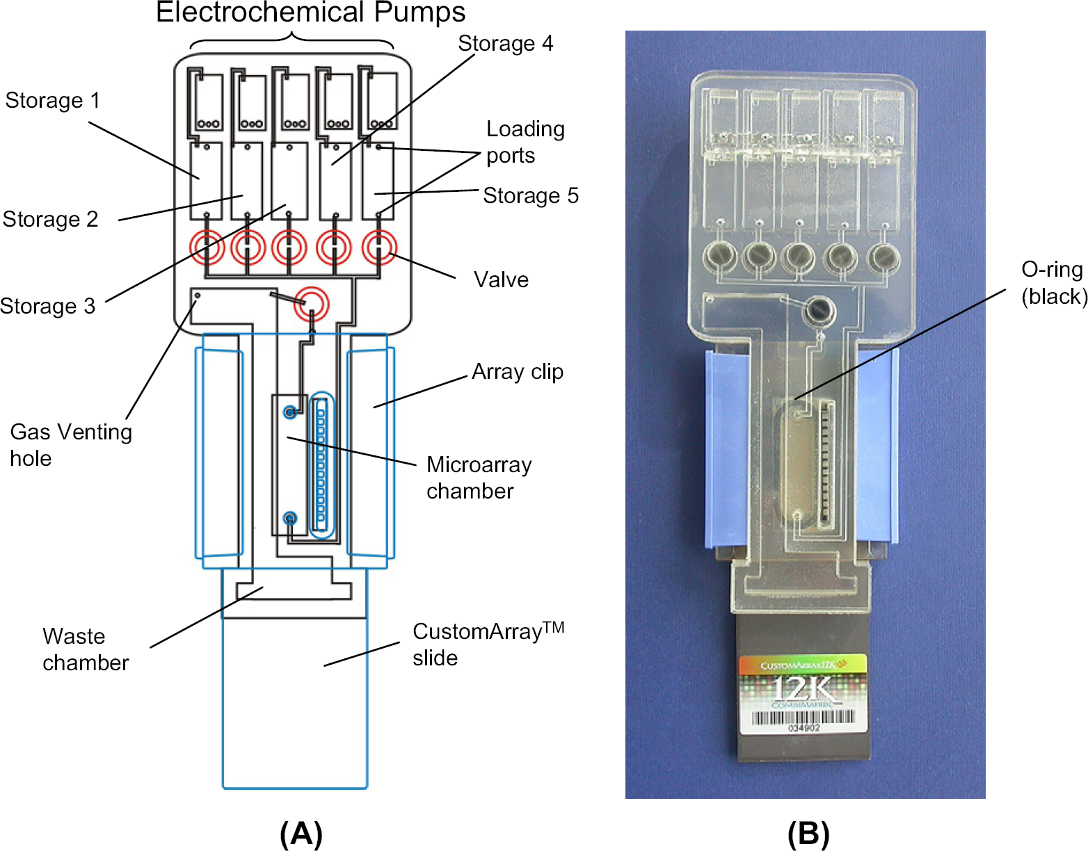
(A) Schematic of the microfluidic device that consists of a microfluidic cartridge and a CombiMatrix CustomArray slide. The microfluidic cartridge consists of five electrochemical micropumps (on the top row), six duckbill check valves, five chambers for the storage of different buffers and reagents (i.e., storage chambers 1 ∼ 5), an array chamber, and a waste chamber. Each storage chamber has two loading ports: one is used to load solution whereas the other one is used to vent out the gas during the loading. The cartridge was assembled with the slide CustomArray using two clips and an O-ring. (B) Photograph of the integrated device.
The microarray contained broad-scan probes designed to detect unique sequences within conserved genes of 32 different species of bacteria, including (but not limited to) B. anthracis, B. cereus, B. halodurans, B. subtilis, B. thuringiensis, Brucella melitensis, Brucella suis, Clostridium botulism, Coxiella burnetii, Escherichia coli, Franscisella tularensis, Salmonella typhimurium, and Yersinia pestis. Probes were selected to be exclusive to a given species as judged by pairwise BLASTN. 15 The probes were designed to have similar annealing stability as judged by a nearest neighbor thermodynamic model, 16 and were designed to have a T m of 50 °C. Probes that had significant secondary structure (T m > 40 °C) were taken out of the set. The probe design file for array synthesis was generated with Layout Designer (CombiMatrix Corp., Mukilteo, WA).
Microfluidic Cartridge
Coupling with the CustomArray slide is a microfluidic plastic cartridge that consists of five micropumps, six microvalves, five chambers for the storage of different buffers and reagents, a microarray hybridization chamber, and a waste chamber, as shown in Figure 1. The plastic cartridge measures 40 × 76 × 10 mm and has channels and chambers that range from 500 μm to 3.2 mm in depth and 0.5 to 8.5 mm in width. The prototype of the plastic cartridge consists of multiple layers of acrylic materials that are laminated and assembled using double-sided adhesive tapes. All the layers, including five layers of acrylic sheets with various thicknesses ranging from 0.5 to 5.7 mm (MacMaster-Carr, Atlanta, GA) and four layers of double-sided adhesive tapes (Adhesive Research Inc., Glen Rock, PA), were machined using a CO2 laser machine (Universal Laser Systems, Scottsdale, AZ). The 5.7 mm thick acrylic layer had six valve seats in which six duckbill check valves (Vernay Laboratories Inc., Yellow Springs, OH) were glued using an epoxy. These check valves were normally closed, and could be opened when the upstream pumping pressure exceeded the cracking pressure of the valves. The valves were used to retain the liquid solutions in their storage chambers and prevent cross talk of the solutions between two adjacent chambers. The implementation of these check valves did not require microfabrication process, and their operation required no external actuation. As a result, they are less expensive and easier to integrate and operate than most conventional microvalves. 1 – 20 After assembly, stainless steel wires with 0.5 mm diameter were inserted into the electrochemical pumping chambers followed by sealing with an epoxy. Each electrochemical pumping chamber was then loaded with 50 μL of 1 M Na2SO4 solution to form an electrochemical pump. The electrolyte loading holes were subsequently sealed using an adhesive tape (Adhesive Research Inc., Glen Rock, PA). These electrochemical micropumps relied on electrolysis of water between two stainless steel electrodes in the electrolyte solution (1 M Na2SO4) to generate gases when a DC current was applied. 13 The generated gas (H2 and O2) was used to move liquid solutions from chamber to chamber in the device. The micropumps also served as an actuation source for micromixing in the array chamber. 14 The venting hole of the waste chamber was sealed with a hydrophobic membrane vent (Sealing Devices, Lancaster, NY) that allowed gas molecules to pass through while the liquid solution was retained in the waste chamber. The plastic cartridge was then assembled with the microarray slide using two clips and a silicone O-ring (Fig. 1). The O-ring was used to form the hybridization chamber on the array chip.
The microfluidic cartridge was designed to take advantage of the gravity to remove the air bubbles from the system when the device was placed vertically during operation. For example, the hybridization chamber was designed with a depth of 600 μm and a width of 6.5 mm, and fluid volume was on the order of tens of microliters. The Reynolds number for the fluid flow was less than 10. 21 Gravity played an important role in fluidics in the hybridization chamber when the chamber was placed vertically. In this chamber where the liquid solutions and gas bubbles entered from the lower portion, buoyant force allowed gas bubbles to travel quickly to the upper portion of the chamber, leaving the chamber bubble-free.
Genotyping Assay
Amplicons for strain typing were generated from B. anthracis genomic DNA (obtained from Dr. L. Wasieloski, USAMRIID) as template. The amplification method consisted of two steps. The first was performed to amplify the double-stranded DNA fragments. The 50-μL reaction contained 1 ng of bacterial genomic DNA and 0.2 μM of each forward and reverse primers. The PCR cycling included an initial denaturation at 94 °C for 3 min, followed by 35 cycles of 94 °C for 30 s, 50 °C for 30 s, and 70 °C for 60 s. The resultant amplicon was purified using a Qiagen QIAquick PCR purification kit (Qiagen, Valencia, CA), and then subjected to a second amplification with only the reverse-specific primer for 35 cycles to produce single-stranded DNA fragments. The DNA was labeled during this step using biotin-14-dCTP (Invitrogen, Carlsbad, CA). Single-stranded target was purified using a Qiagen QIAquick PCR purification kit, and 500 ng of target was loaded into the array chamber in the cartridge.
During the on-chip genotyping assay, 95 μL of the hybridization solution containing the biotinylated DNA in 6 × SSPE and 0.05% SDS was loaded into the array chamber in the cartridge. Other solutions including (1) 200 μL of 6 × SSPET (saline–sodium phosphate–EDTA–Tween 20) washing buffer; (2) 200 μL of 3 × SSPET washing buffer; (3) 200 μL of 2 × PBST (phosphate-buffered saline–Tween) buffer; (4) 200 μL of a labeling solution; and (5) 200 μL of 2 × PBST buffer were separately loaded in the storage chambers 1–5 (Fig. 1A). The labeling solution contains streptavidin-Cy5 (Molecular Probes, Eugene, OR) that was diluted in a blocking solution (2 × PBS, 0.1% Tween-20, 1% acetylated BSA) to a final concentration of 1 μg/mL. After sealing the loading ports using a sealing tape (Adhesive Research Inc., Glen Rock, PA), the integrated device was then inserted into an instrument, which provided hybridization heating, temperature sensing, and electrical power for liquid pumping and mixing. The instrument is measured as 140 × 200 × 200 mm. It consists of a clamping manifold, a printed circuit board, and a power supply. The microfluidic device was inserted into the manifold where a thin-film heating element (Minco Corp., Minneapolis, MN) was pressed on the microarray slide of the device to provide the heating of the array chamber during the hybridization process. The thin-film heating element consists of a temperature sensor that provided the temperature feedback to the control circuit board. A flexible cable connector was used to connect the circuit board with the electrical pins for the electrochemical pumps in the cartridge. The board provides electronic control of the hybridization heating, temperature sensing, and electrical power for liquid pumping and mixing.
The on-chip process started with a 1-h hybridization in the microarray hybridization chamber at 45 °C, followed by a three-step on-chip washing process. During the washing process, the nonstringent 6 × SSPET washing buffer was first pumped through the hybridization chamber, removing the sample mixture into the waste chamber and washing the array chip. The stringent 3 × SSPET washing buffer, followed by the 2 × PBST buffer, was subsequently pumped through the hybridization chamber to ensure a thorough washing and removal of nonspecific binding. After the on-chip washing steps, the labeling solution was pumped into the hybridization chamber followed by a 30-min incubation at room temperature. Once the labeling was completed, the 2 × PBST buffer was pumped through the hybridization chamber to ensure a thorough washing and removal of residual labeling reagents. During each pumping step, a bubbling mixing procedure was implemented. 14 The device was then removed from the instrument. The total on-chip processing time is approximately 1 h 50 min. The microarray chip was detached from the microfluidic plastic cartridge before it was scanned using a commercial fluorescent scanner (GenePix 4000B, Molecular Devices, Sunnyvale, CA). Imaging was performed while the array was wet with 2 × PBST under a LifterSlip glass cover slip (Erie Scientific, Portsmouth, NH). Image intensities were analyzed and quantified using Microarray Imager software (CombiMatrix Corp., Mukilteo, WA). Genotype identification was accomplished by averaging the species-specific broad-scan probe signal intensities and graphing in Microsoft Excel.
Controls for monitoring the efficiency of genotyping by the cartridge were performed with the same protocol, however, conventional hybridization chambers that have no integrated microfluidic components were used. All of the fluidic handling and processes were carried out manually using hand-held pipettes. For manual processing, each fluidic handling step started with emptying the hybridization chamber using a pipette followed by loading a fresh solution into the chamber using another pipette. The hybridization was performed in a rotisserie oven for 1 h at 45 °C. Washes were performed at room temperature for 30 s. Labeling was performed at room temperature for 30 min. The total control processing time for the genotyping assay was approximately 2 h.
Results and Discussion
The microfluidic components, including electrochemical micropumps, duckbill check valves, and bubbling micromixers, are simple, low cost, and easy to fabricate and integrate into the plastic cartridge, resulting in a cost effective, manufacturable, and disposable device. Fluidic tests showed that the check valves prevented liquid cross talk between two adjacent chambers and provided efficient isolation of liquid solutions in their storage chambers. Moreover, a normally closed valve between the array chamber and waste chamber prevented evaporation of the hybridization solution during the 1-h hybridization process at 45 °C. The duckbill is a precision, one-piece elastomeric check valve that allows flow in one direction and checks flow in the opposite direction. These normally closed check valves are made of silicone and could be easily glued on the valve seats in the cartridge using epoxy. Once the upstream pumping pressure exceeded the cracking pressure of the valves, the valves were opened. The implementation of these check valves did not require a microfabrication process, and their operation required no actuation. As a result, they are less expensive and easier to integrate and operate than most conventional microvalves. 17 20
The electrochemical micropumps were also simple in design and easy to operate for pumping liquid solutions in the cartridge. 13 Gas generated from the electrochemical pumps moved liquid solutions from chamber to chamber in the device. A DC voltage of 4 V generated a pumping rate of 100 μL/min, indicating that a battery-powered operation is possible. The pumps were also excellent sources to provide gas bubbles to enhance micromixing in the array chamber during the washing and reaction steps. 14 Because the Reynolds number for the fluid flow in the hybridization chamber was less than 10, fluid flows at such a low Reynolds number were predominantly laminar. 21 As a result, mixing in the hybridization chamber was dominated by diffusion. A pure diffusion-based mixing process can be very inefficient and often takes a long time. The bubbling mixing technique developed here is based on the continuous bubbling effect. During the mixing steps, gas bubbles generated from the electrochemical micropump entered into the hybridization chamber from the lower portion. Buoyant force allowed gas bubbles to travel quickly to the upper portion of the chamber. During this traveling process, the two-phase flow resulted in flow recirculation in the liquid solution around the bubbles. 22 As a result, the mixing was enhanced in the chamber. The use of gas bubbles to enhance mixing in the microfluidic chamber proved to be a simple but effective micromixing technique without the use of any external actuation methods such as physical rotation or acoustic agitation. 23, 24
The microarray contained broad-scan probes to identify bacterial genotypes based on unique probes for each strain type. Upon hybridization of biotinylated amplicon to the arrays, the fluorescent signal obtained using the microfluidic cartridge demonstrated a highly similar pattern for arrays processed manually (Fig. 2). Results obtained on using the microfluidics device were comparable to the manual control results, and the average signal intensities for B. anthracis-spe-cific probes were 1224 and 1163 arbitrary intensity units, respectively, and the negative probe and background signals were below 65, suggesting that on-chip microfluidic washing and labeling are efficient and compatible with manual washing and labeling processes. This further indicated that the hybridization and fluid handling (washing and reaction) could be automated using the integrated microfluidic device with no loss of performance.
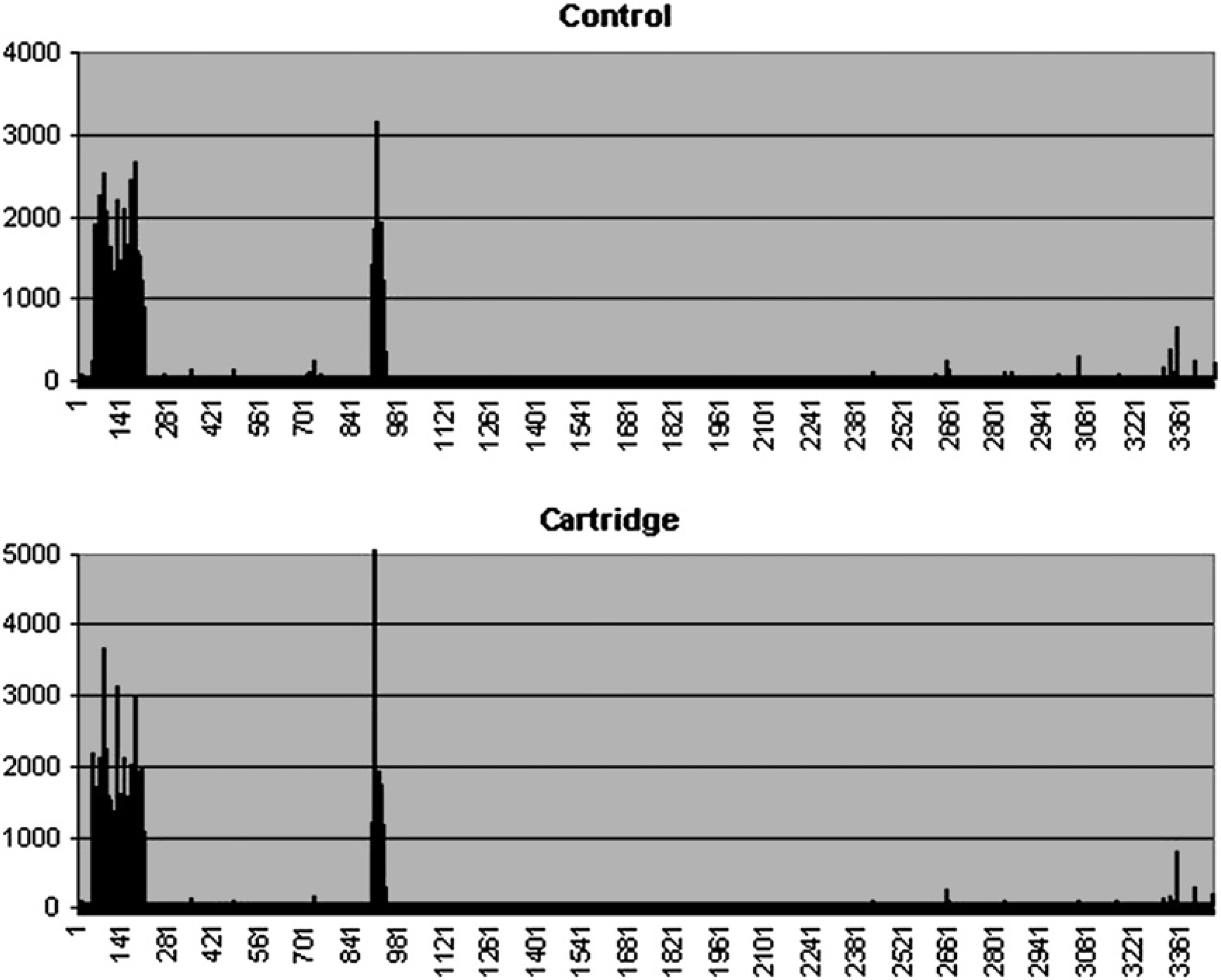
Fluorescent signal obtained from B. anthracis target hybridized to an array processed manually (control) and an array processed automatically using the microfluidic device (cartridge), indicating consistent results between the two methods. The data shown represent the average probe intensities obtained from three replicate features. There were 3460 unique oligonucleotide probes on the array, representing 58 different strains of bacterial and viral pathogens.
By averaging the species-specific broad-scan probe signal intensities and graphing the results (Fig. 3), it showed that the B. anthracis target DNA also hybridized to the nearly identical B. cereus and B. thuringiensis probes. As expected, the broad-scan probes are able to distinguish between most species of bacterial organisms. However, the broad-scan probes are not able to effectively discriminate between the species that share almost identical sequences. A series of probes each with a single nucleotide polymorphism (SNP) in the middle of the probe were analyzed for their ability to discriminate between the highly related Bacillus species. As shown in Figure 4, when the array was hybridized with single-stranded DNA amplified from B. anthracis, the SNP probes designed for the detection of B. anthracis had higher signal than probes corresponding to both B. thuringiensis and B. cereus. To demonstrate the reproducibility of the device, Figure 5 shows a comparison of two different arrays both processed using the microfluidic cartridge. The scatter plot of feature intensities demonstrates that the automatic processing produced highly consistent results with a correlation coefficient (R 2) of 0.9031 (Fig. 5).
Average species-specific probe intensities obtained from B. anthracis target for both manually (control) and automatically (cartridge) processed arrays. The data represent a subset of 13 pathogens from the array for which the averages of intensities for broad-scan probes were graphed. The automated microfluidic system was able to detect hybridization of probes to B. anthracis and its near-neighbors B. cereus and B. thuringensis, with results equal to those of the manual technique.
Ability of the microfluidic hybridization and wash system to specifically identify B. anthracis from nearly identical sequences. The signal intensities of probes designed to discriminate B. anthracis (blue column) from B. thuringiensis and B. cereus (red column) by the SNPs indicated were consistently higher.
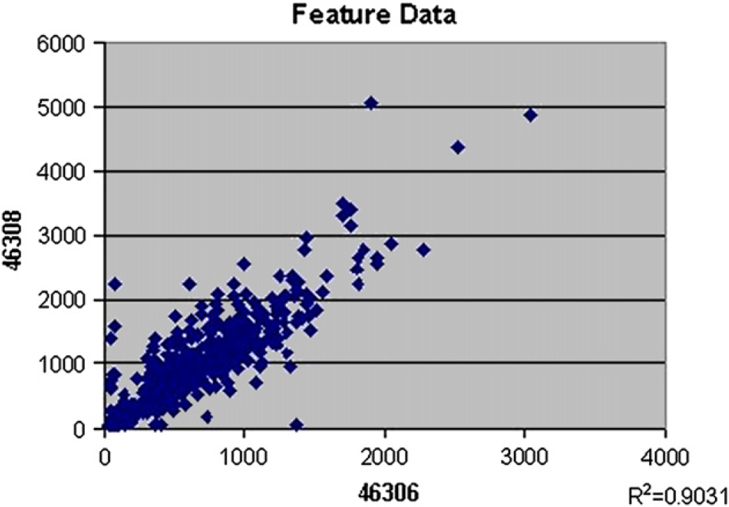
Scatter plot of the individual feature intensities comparing two individual arrays (the array bar code is indicated on the corresponding axis) both processed using the microfluidic cartridge, demonstrating the highly reproducible and robust nature of the microfluidic system.
The integrated microfluidic device automates microarray assays that involve multistage sample processing and fluid handling that are in general labor intensive and time consuming. Although only detection of B. anthracis was demonstrated in this study, the integrated microfluidic platform can potentially be applied to many other bacterial genotyping assays. Automation of the microarray process allows more stringent manufacturing control over not only the microarray but also the quality and volume of the reagents. In addition, there are more controls over a variety of parameters including hybridization temperature and time, washing time and speed, mixing/agitation speed, and labeling time. The microfluidic device can eliminate variations in array data caused by subtle, day-to-day differences in protocol and manual handling. Although some commercial robotic workstations have also been developed to automate microarray processing, these instruments are generally bulky, expensive, and complicated to operate and maintain. In contrast, the self-contained and fully integrated microfluidic array devices reported here are disposable and require simple, portable, and inexpensive instruments for operation. The integration of microfluidics adds new significant functionalities to the conventional microarray platform. Although the sample and reagent consumption in the current microfluidic device design is on the order of tens of microliters, it is believed that the design could be further miniaturized so that the sample and reagent consumption could be significantly reduced. It is also possible to fabricate inexpensive microfluidic cartridges using high-volume injection molding technique instead of laser machining, which is only suitable for rapid prototyping. We are currently investigating the integration of microfluidic cartridges with electrochemical detection (ECD)-based microarray. 10 The ECD will allow on-chip scanning of the microarray chip while it is still coupled with the microfluidic cartridge. As a result, it is unnecessary to remove the chip from the cartridge for fluorescent scanning. The ECD signal read out will no longer be visual and rely on fluorescence that often suffers from photobleaching issues, but rather be electrochemical relying on the intrinsic electronic functionality of the silicon integrated circuit chip. The integrated microfluidic platform provides a step toward fulfilling the promise of rapid, automated genetic analysis in cost effective and portable instruments.
Conclusion
A self-contained and disposable microfluidic array device for detecting specific sequences of bacteria has been developed. The device automated and integrated hybridization, sample processing, and fluid handling steps that are considered labor intensive and time consuming in regular manual handling process. All microfluidic components such as micropumps, microvalves, and micromixers are integrated on the microfluidic cartridge, but use simple and inexpensive approaches to reduce device complexity. The genotyping results showed that the microfluidic array device identified B. anthracis and demonstrated the potential of integrated microfluidic and microarray technology for identifying biowarfare agents.
Acknowledgment
The authors thank Kia Peyvan, Marty Ross, Alla Petrova, Jeff Kemper, and Al Pierce for technical support and useful discussions. This work has been sponsored by DoD contract #1999011104A.