
Abstract
We extend the toolbox of lab procedures in life sciences by development of centrifugal microfluidics for high-level process integration. This is accomplished by implementing novel functional principles for sedimentation, batch-mode mixing, frequency-dependent online flow control, and optical read-out, which can be integrated into a process chain. The modular centrifugal setup comprises a microstructured disposable polymer disk as well as a reusable spinning and detection unit. We successfully developed centrifugal microfluidic technologies, which are suitable for sample preparation, process engineering, personalized diagnostics, and hematology, on this platform.
Introduction
The advent of microfluidic technologies over the last couple of decades has been vigorously boosted by the prospects of process integration, miniaturization, and parallelization in life sciences, 1 –10 primarily for medical diagnostics and drug discovery. 11 –13 So far, key laboratory unit operations such as sample injection, separation, metering, mixing, reaction, and detection have been successfully demonstrated by separate stand-alone microfluidic devices. Several of these microfluidic technologies are well competitive or even far superior to conventional technologies. Crucial advantages are reduced consumption of sample and reagent volumes, reduced size as well as short times-to-result, and even the high measurement accuracy. However, the wide-scale commercial success will be determined primarily by the ability to meet the stringent end-user demands on reliability, user friendliness, and, overall, the costs per test.
Several microfluidic “lab-on-a-chip” platforms have been developed to comply with the technical and economic market requirements, among them chip-based electrophoresis, 14,15 droplet-based digital microfluidics, 16 and several well-plate based liquid handling technologies for high-throughput screening. 17
We describe a novel and versatile centrifugal microfluidic lab-on-a-chip platform. The modular setup of such a “lab-on-a-disk” 18 –27 comprises a reusable macroscopic detection unit and a spinning drive in which a possibly disposable polymer disk typically hosting passive microstructures is placed. 28 –32 The disk characteristically features inlet ports for the sample and reagent uptake as well as microchannels and microstructures where the sample is transported and processed 33 –40 by the interplay of centrifugal (volume) forces and capillary (surface) forces. The nature of the final step can be the collection of the processed substance or the read-out of an assay result, depending on whether an analytical assay, 41 –43 a preparative procedure, 44,45 or a synthesis has been implemented in a lab-on-a-disk system. Numerous “lab-on-a-disk” products have already been launched in the market. 46 –53
The paper is structured as follows. The subsequent sections describe the basic centrifugal operating principles to realize laboratory unit operations such as flow control and metering, particle (blood) sedimentation as well as mixing in batch mode and continuous flow. Afterwards, read-out concepts for two common types of bioanalytical assays, that is, colorimetric absorbance assays and (multiplexed) fluorescent immunoassays, are outlined. Finally, our development toolbox comprising prototyping 54 and flow visualization techniques 55 to rapidly arrive at problem-specific solutions is presented.
Flow Control and Metering
Diagnostic point-of-care systems require a fully integrated process chain from the preparation of an untreated sample of human whole blood obtaining an analytical result. The basic laboratory unit operations for analytical applications are flow control and metering. Liquid samples are inserted into the microstructured channels near the center of the polymer disk and transported by centrifugal force F v towards the radial direction 33 (Fig. 1). The flow velocity u depends on the frequency of rotation v and the channel geometry. 33,36,56
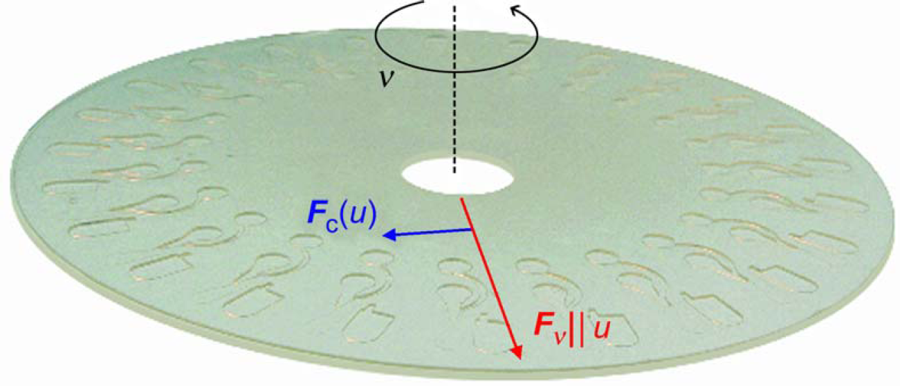
A disk with the format of a conventional compact disc (CD) and 24 integrated microfluidic structures. The centrifugal force F v induced on a liquid plug within a channel points in the radial direction. In the reference frame rotating with the disk and liquid with a flow velocity u, the Coriolis force F C acts perpendicular to the centrifugal force.
When the resulting flow is observed from a noninertial reference frame rotating at the spinning frequency (i.e., with the disk at rest), an apparent Coriolis force F C component arises, which is perpendicular to the radial direction (Fig. 1). We show that beyond a critical frequency of typically a few 100 rad s−1, which can be readily reached by a drive unit, the transverse Coriolis force F C prevails over all other forces including the strong centrifugal force F v. This allows a user to switch the liquid in a channel without additional external actuators. 34 –36 This effect is demonstrated by a flow switch in a symmetrically structured Y-channel (Fig. 2).
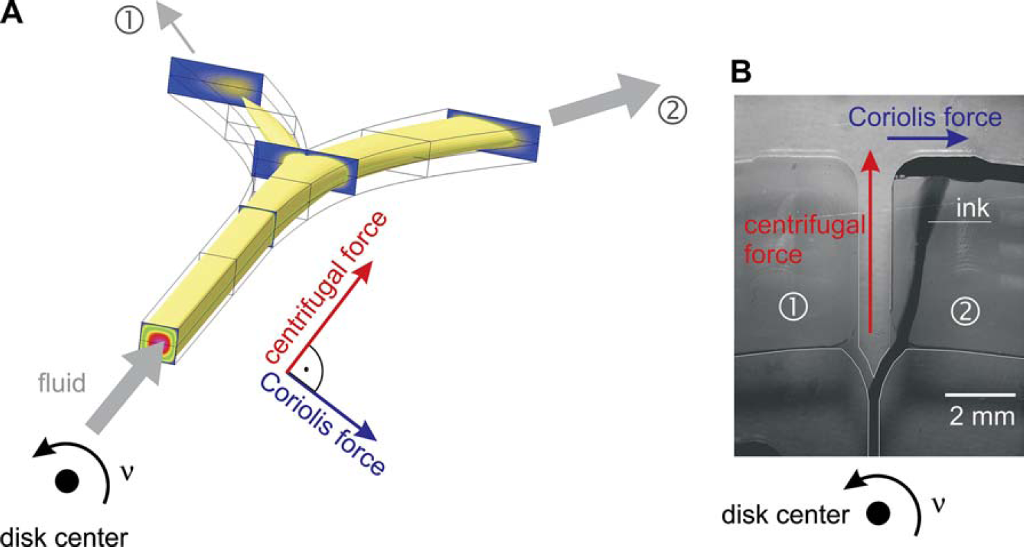
(A) Simulation (CFDRC-ACE +) 81 of the switching of flow between the two outlets on an inverse Y-structure based on the Coriolis force. (B) The experimental switch structure. The Coriolis-induced redirection of flow into the right outlet can be clearly recognized.
If Coriolis effects did not exist, the flow would be evenly split among the two outlets. However, a dominating Coriolis force F C induces a bias, eventually directing 100% of the flow into one particular outlet, which can be addressed according to the direction of rotation. This Coriolis force F C can, for instance, be implemented as a frequency-dependent switch for a sequence of centrifugal flows in preparative protocols.
The so-called capillary burst valves 22,27,57 (Fig. 3) are used to stop the centrifugally driven flow at a hydrophobically coated constriction up to a critical frequency threshold v c. This burst frequency of the passive valve is determined by the radial length and the radial position of the metered liquid plug as well as the contact angle of the coating and the geometric cross section of the constriction at the time of fabrication.
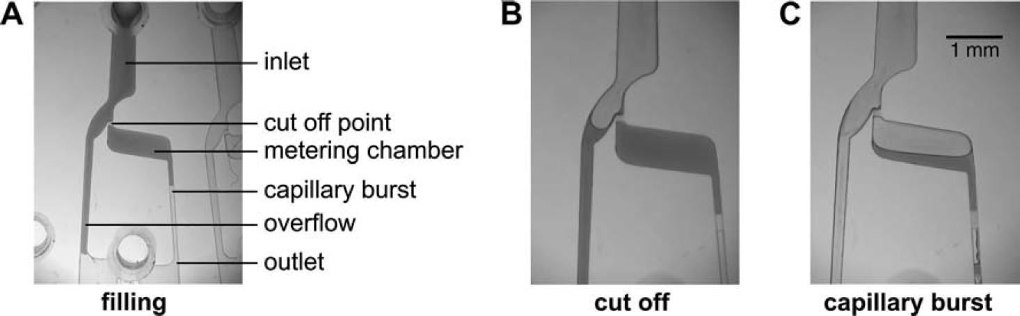
Metering structure based on a capillary burst valve. (A) The fluid network is filled with an undefined sample volume. (B) After the metering chamber is filled, the residual fluid is cut off. (C) The disk spins above a critical frequency v c and the capillary burst valve breaks. Thus the precisely metered sample volume is purged out of the metering chamber.
In combination with an overflow channel, these hydro-phobic valves can also provide a metering function (i.e., they define a volume). After filling the entire fluidic network with liquid of an excess volume (Fig. 3A), the liquid is stopped at the outlet of the metering chamber by a capillary burst valve. The residual liquid is cut off in a separate waste outlet by spinning below the burst frequency v c of the valve (Fig. 3B). Surpassing v c, the liquid is then purged out of the metering chamber (Fig. 3C). We designed metering structures from the μL-range down to the nL-range with an extremely high reproducibility, for example, a 300-nL volume is metered with a quality of CV < 5%.
Blood Sedimentation
An important objective in medical diagnostic systems is the integration of the full process chain from the preparation of a patient's whole blood obtaining an analytical result. The first unit operation is usually the separation of red blood cells (RBCs) from the plasma for subsequent analysis. Although several microfluidic approaches for a batch separation of blood have been presented so far, 18,23,47 a robust and integrable separation structure essential for complete on-disk processing is lacking. The rotating platform is well suited to this task because of the intrinsic sedimentation. The RBCs possess a higher mass density (about 6%) with respect to the surrounding plasma. These particles are consequently driven by a centrifugal field toward the bottom of a chamber. Our three-stage continuous flow separation scheme 44 is depicted in Figure 4.
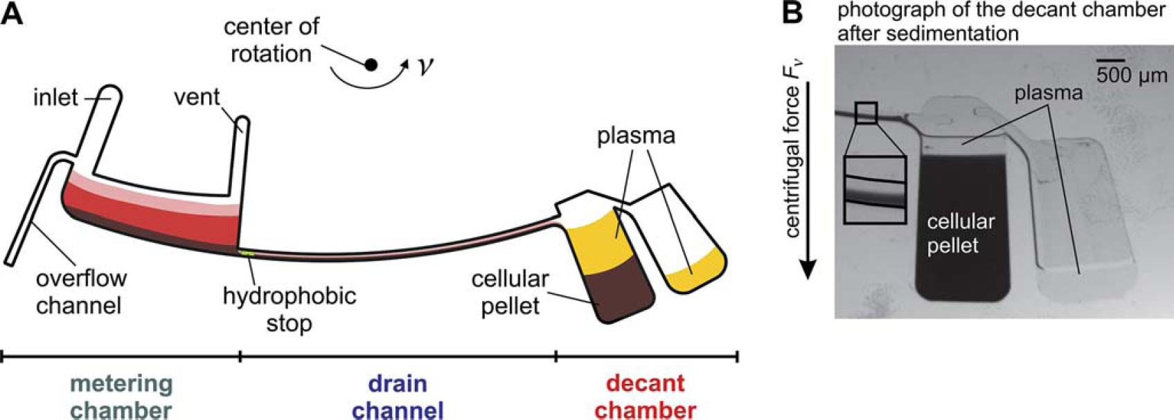
(A) Continuous flow scheme in our three-stage separation structure. A blood sample flows from the metering chamber via the drain channel into the decant chamber for final separation. (B) Decant chamber: purified plasma overflows into a separation reservoir while the cellular pellet remains at the bottom of the decant chamber.
First, the metering chamber is filled by capillary action with a droplet of human whole blood extracted from the fingertip while the disk is at rest. Afterwards a sample volume of 5 μL is metered under moderate rotation (∼12 Hz) between an overflow channel next to the inlet and a hydrophobic stop at the outlet of the chamber. Beyond a burst frequency of 15 Hz, sedimentation is initiated through the drain channel into the decant chamber where presepa-rated blood accumulates. The volume capacity of this decant chamber slightly exceeds the volume fraction of the cells. Therefore, only purified plasma with a cell concentration of less than 1% overflows into a subsequent reservoir where it is available for further processing. This way, 2 μL of plasma is retrieved from the initial 5 μL whole blood sample. The separation time of this continuous centrifugation scheme is governed by the flow resistance of the drain channel. Typical separation times of 20 s can be achieved at spinning frequencies of 40 Hz.
Stopped-Flow “Batch” Mixing
After metering, an immunological assay, to be completely integrated on a miniaturized platform, typically features a mixing and/or dilution step at stopped flow. Here it is crucial to implement rapid mixing. However, because of the strictly laminar conditions in microfluidic systems, mixing is limited by diffusion. 58 The only way to accelerate mixing is by reducing the diffusion length, which has successfully been achieved in our approach by implementing two strategies. In the first approach, magnetic beads that are prefilled in an on-disk mixing chamber pass upon spinning a set of conventional permanent magnets resting in the lab frame. 45,59,60 These magnets are specifically aligned to periodically deflect the magnetic beads. Instead of applying a time varying magnetic field, we rotate the chamber generating a time-oscillating magnetic force on the magnetic beads. In consequence, the beads are periodically deflected radially inward and outward inducing chaotic advection to the liquid phase by means of the Stokes drag (Fig. 5). In addition, the beads can be used as solid phase on which a reactive layer can be coated, so that the reaction with target molecules in a sample is accelerated.
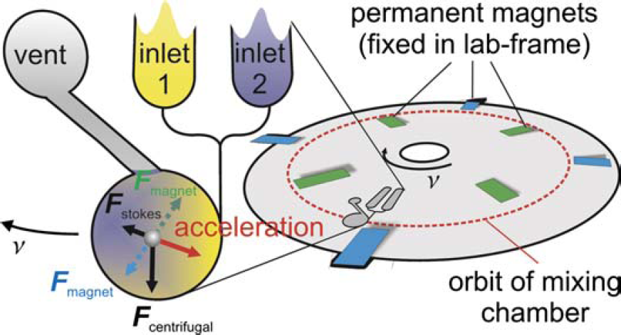
Magnetohydrodynamically enhanced mixing in a chamber filled with beads.
In the second approach (“shake-mode”), the sense of rotation is frequently reversed. 61 This way, the inertia of the liquid induces twisting patterns significantly reducing the diffusion length (Fig. 6).
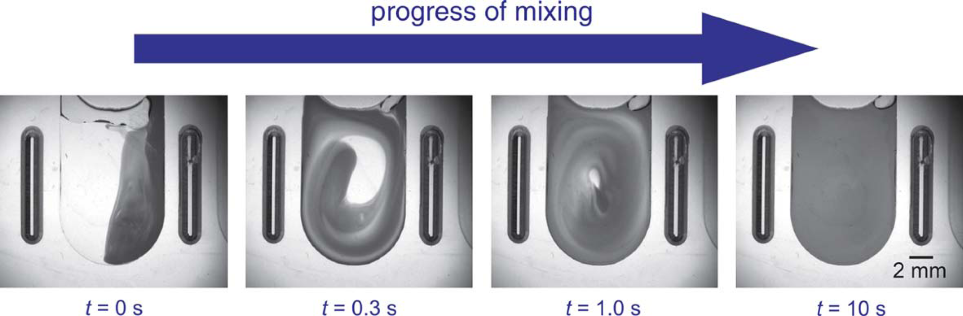
Progress of mixing by using “shake-mode”. Frequent reversal of the sense of rotation induces advective currents by inertia.
In our mixing chamber, we experimentally observed a drastic reduction in the characteristic mixing time, 45,61 from 7 min for mere diffusive mixing to 3 s for plain inertial mixing and down to 1.3 s by the magnetic bead enhanced mixing. By combining the mixing with beads and inertia, the mixing time could even be cut down to 0.5 s (Fig. 7).
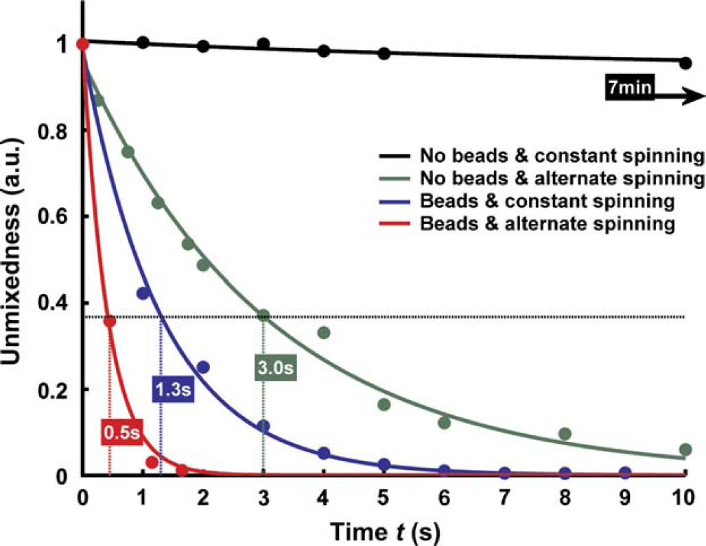
Decrease of unmixedness as mixing proceeds: as a benchmark, a characteristic mixing time τ is defined as the 1/e-decay of the mixing state. Compared to mere diffusion with τ = 7 min, bead-based magnetohydrodynamic mixing in alternating spinning mode accelerates the mixing process by three orders of magnitude.
Continuous-Flow Mixing
We also extended the centrifugal microfluidic platform to facilitate high-throughput continuous flow applications. This continuous flow scheme uses the centrifugal volume force F v generated by the rotating drive to both pump and mix the liquid educts. The hydrodynamically induced mixing is based on the velocity-dependent Coriolis pseudo force F C impacting flows in the rotating frame of reference. The centrifugal force F v generates a parabolically shaped component of the velocity field, which leads to a nonuniform distribution of the transverse Coriolis force F C. The stirring induced by transverse advection in a radial microchannel under rotation is controlled by the speed of rotation. 33 –35 Because of the high-flow rates attributed to the favorable interplay of the strong centrifugal force F v with a large channel cross section, our experiments and accompanying simulations demonstrate high throughputs at extremely reduced mixing times. These characteristics are favorable for applications in chemical microprocess engineering. 37 –40
A commonly used strategy to reduce the diffusion length is the multilamination of continuous flows. 62 –64 Figure 8 shows the realization of a split-and-recombine laminator, 35 based on the transverse advection effect. The initial AB flow pattern is split into three substreams while the Coriolis force F C leads to an inversion of the pattern within the central channel. Thus, an ABAB lamination pattern is formed after the recombination of the substreams.
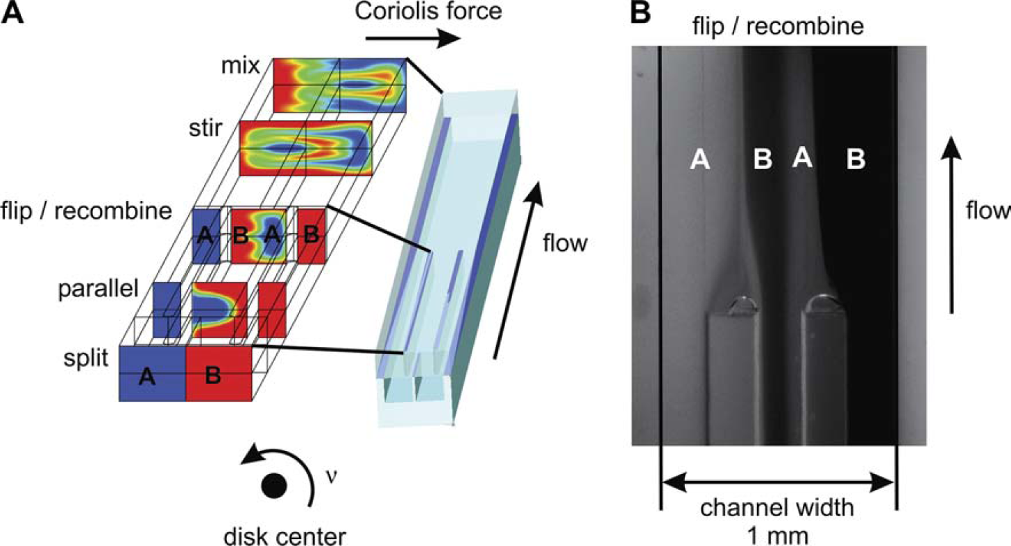
Coriolis-force based advective mixing within a split-and-recombine laminator. (A) A simulation (CFDRC-ACE +) 81 of the induced advection based on the Coriolis force. (B) Multilamination after recombining of the flows.
Read-Out of Colorimetric Assays
The final step of an assay is the read-out. For colorimetric assays, we developed a simple and robust optical concept to enable precise and sensitive read-out. 42 A major inhibitor for the implementation of colorimetric assays on miniaturized lab-on-a-chip platforms is the relatively short optical path length through the measurement chamber, which is limited by the physical dimensions of the system. Several approaches to prolong the optical pathway by an optical on-chip guidance of the interrogating beam have been pursued, 65 for example, based on embedded optical waveguides, 66,67 integrated microlenses, 68 optical fibers, 69,70 or total internal reflection. 71 –73
Our concept of optical beam guidance is based on the total internal reflection at V-grooves that are monolithically integrated at the rear side of the chip (Fig. 9). The probe beam impinging perpendicular to the upper chip surface is deflected by an overall angle of 90° into the plane of the chip. The absorbance length is thus extended by a factor of 10 compared to the path length for direct incidence of 1 mm. Both the simplicity and performance of this novel concept are demonstrated by a glucose assay of human whole blood on a simple and rugged lab-on-a-disk setup comprising a laser diode, a detector, and an exchangeable polymer disk, which is readily amenable to standard polymer micro-machining techniques.
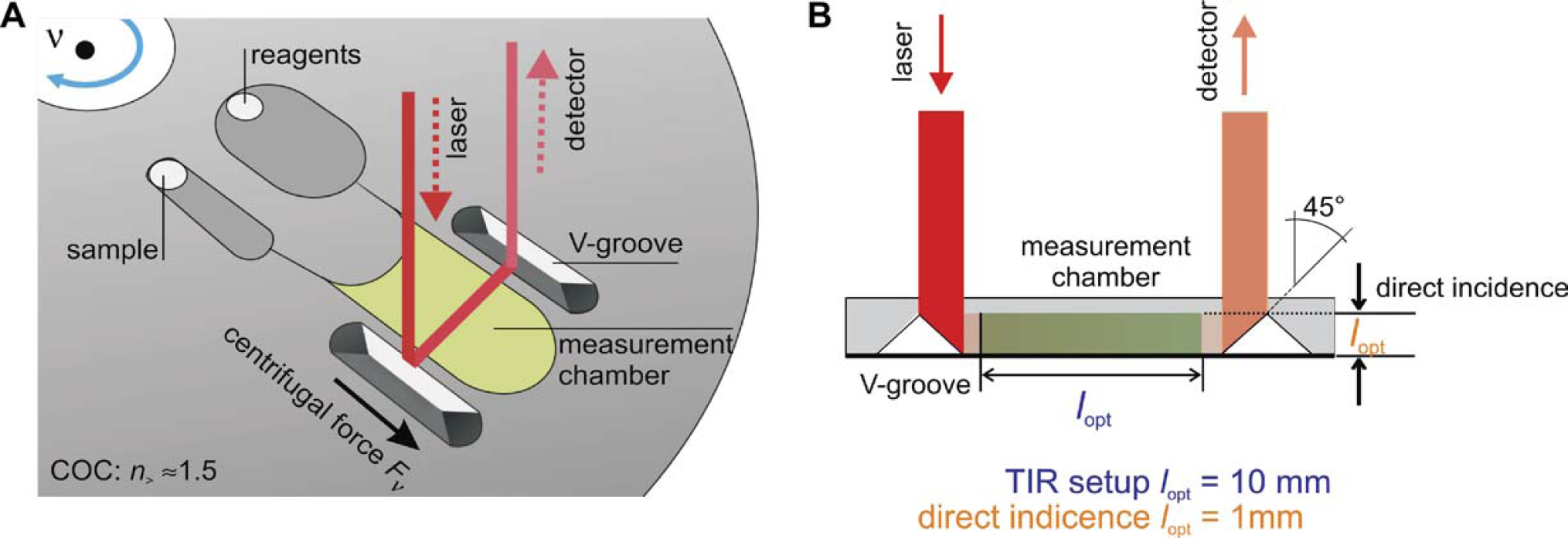
Concept of on-chip optical beam guidance by total internal reflection. The concept significantly extends the optical path length, l opt, on a flat monolithic polymer disk for sensitive colorimetric absorption measurements compared to direct incidence. (A) By spinning the disk, the sample and reagent liquids are transported from their respective inlets into the measurement chamber. (B) Next to the measurement chamber, integrated V-grooves deflect the beam into and out of the disk plane.
The polymer disk features fluidic and optical elements to perform colorimetric assays. The fluidic elements provide ports for sample and reagent uptake connected to a combined mixing and measurement chamber. The liquid transport is entirely controlled by the centrifugal force F v (Fig. 10).
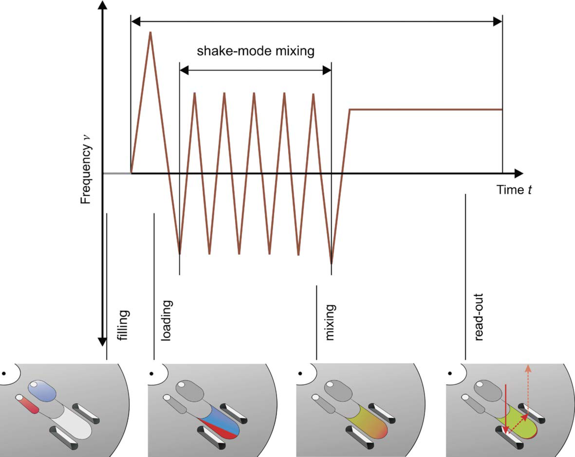
Frequency protocol to conduct a colorimetric glucose assay. After the disk is placed on the spinning drive, the sample and the reagents are loaded into their respective inlet reservoir. Next, the liquids are transported into the measurement chamber by means of the centrifugal force. Mixing is completed within 5 s by frequently reversing the sense of rotation (“shake-mode”). The initial glucose concentration is determined during spinning to allow disk-based real-time monitoring of biochemical processes.
This read-out strategy is successfully validated by the determination of glucose, hemoglobin, and alcohol in human whole blood. We use a sample droplet of untreated human whole blood from the fingertip. After the uptake of sample and reagent, the liquids are centrifuged in a measurement chamber. The diffusion-limited speed of the reaction is enhanced by inertially induced advection using the “shake-mode”. 61 Next, the RBCs in the measurement chamber are sedimented out of the optical pathway. Unlike membrane-based blood filtration, this integrated sedimentation step makes the eventual measurement of the glucose concentration independent of the hematocrit.
To shorten the time-to-result of the enzymatic assay, the increase of the absorbance is monitored in real-time during constant spinning and the saturation values, defined by the biochemical reaction, are extrapolated by a regression fit to the recorded data points (Fig. 11A). This real-time method drastically reduces the time-to-result from several minutes to about 50 s. To show the linearity of the assay, we plotted the saturation values against the glucose dilution series (Fig. 11B).
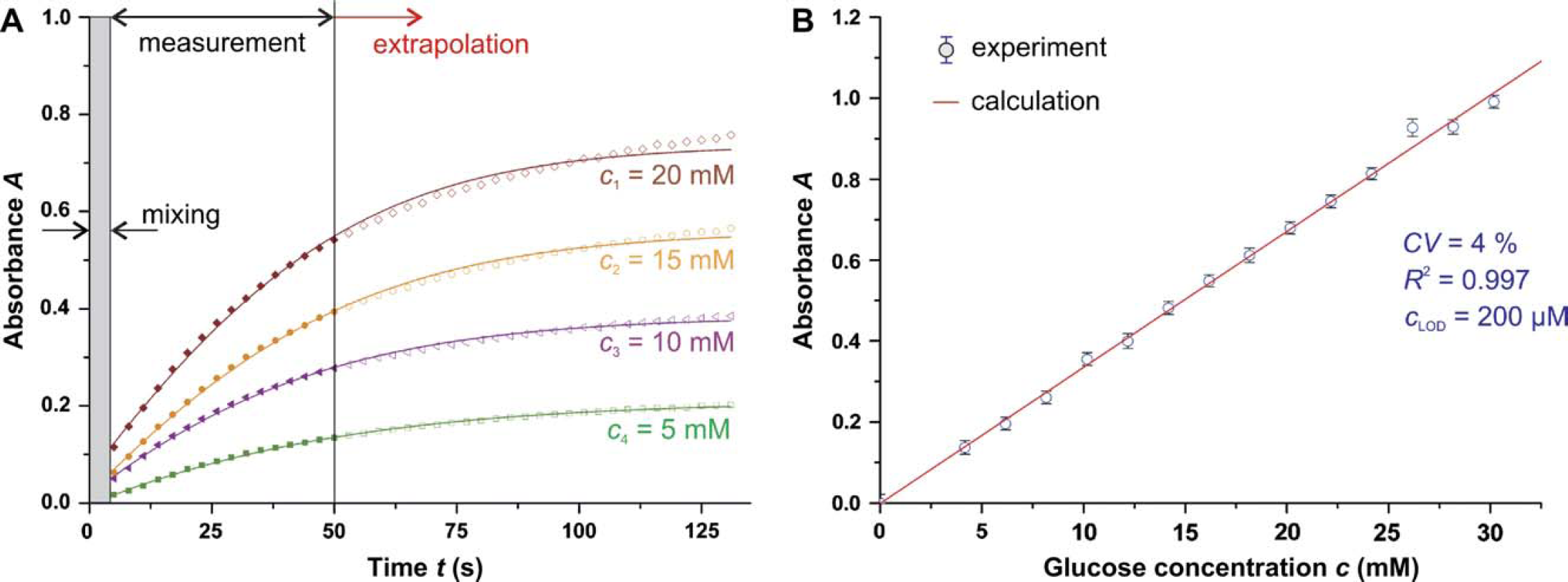
(A) Real-time read-out of the colorimetric assay and extrapolation of the saturation value to shorten the time-to-result. After mixing, the increase of absorbance is recorded for t = 45 s, and the saturation value is extrapolated by regression fit to the recorded data points. (B) Results of glucose determination with human whole blood as sample and measurement of the saturation value.
It can be seen that the disk-based colorimetric glucose assay shows an excellent reproducibility of CV = 4%, an outstanding lower limit of detection c LOD = 200 μM, and a high degree of linearity (R 2 = 0.997) over the physiologically and pathologically required area. To run internal calibrations and rule out noise effects, a symmetric fluidic structure with a reference chamber can be integrated. This robust and cost-effective approach can be readily adapted for enzyme-linked immunosorbent assays.
Read-Out of Bead-Based Fluorescence Immunoassays
We developed an optical concept for multiplexed bead-based fluorescence immunoassays on miniaturized microfluidic devices. Polystyrene beads are swollen in an organic solvent suspending quantum-dots (QDs) of a given color. 74 –77 QDs excel with their broadband excitation, spectrally sharp emission, and stability against photobleaching, thus allowing a high degree of parallelization. They, therefore, can be detected by an inexpensive setup comprising a conventional CCD-camera and an LED as well as two optical filters. To implement a fluorescence immunoassay, the QD-encoded beads are first functionalized with capture proteins (Fig. 12).
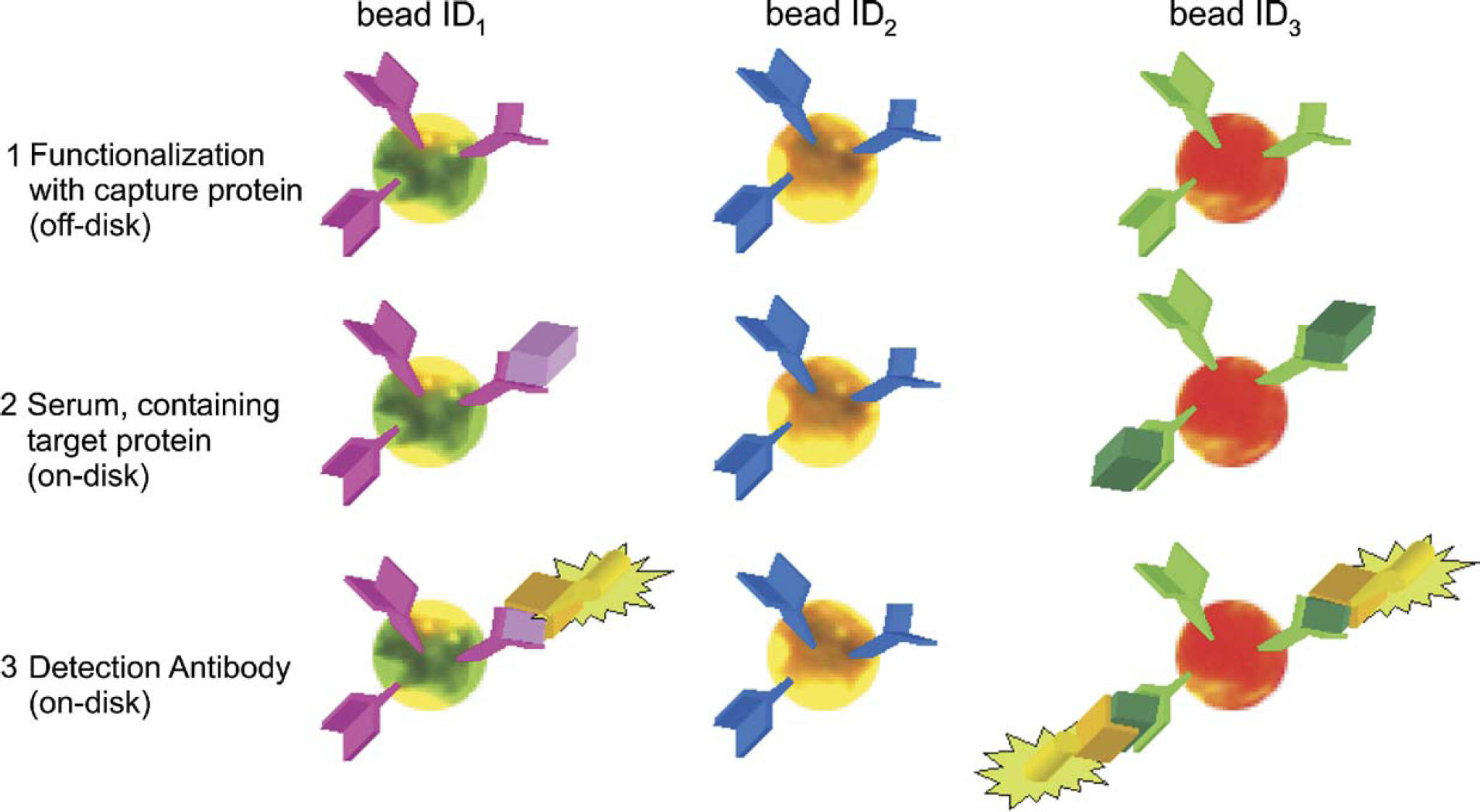
Procedure of a threefold multiplex fluorescence immunoassay on quantum-dot (QD) beads. The beads are first functionalized according to their color tag (the bead ID) with a certain capture protein, mixed and then loaded into the disk-based detection chamber. Next, the serum containing the target antigens is transported into the detection chamber and the specific antigen–antibody complex is formed. After washing, the detection antibodies specifically bind to these antigen–antibody complexes. A final washing step completes the assay procedure.
Next, the beads are loaded into the miniaturized device where they aggregate in the form of a highly periodic monolayer in front of a geometrical barrier. 78,79 Suspensions of beads with 150 mm diameter are loaded into a flat chamber measuring 200 mm in depth by a continuous flow. With the depth smaller than a bead diameter (100 mm), the outlets act as barriers to the beads and force them to accumulate in the chamber. Therefore, the decisive impact parameters are the geometry, particle concentration of suspension, and inlet pressure. A rhombus-like aggregation chamber with an aperture angle of 60 ° fosters hexagonal aggregation patterns leading to the highest package density (Fig. 13).
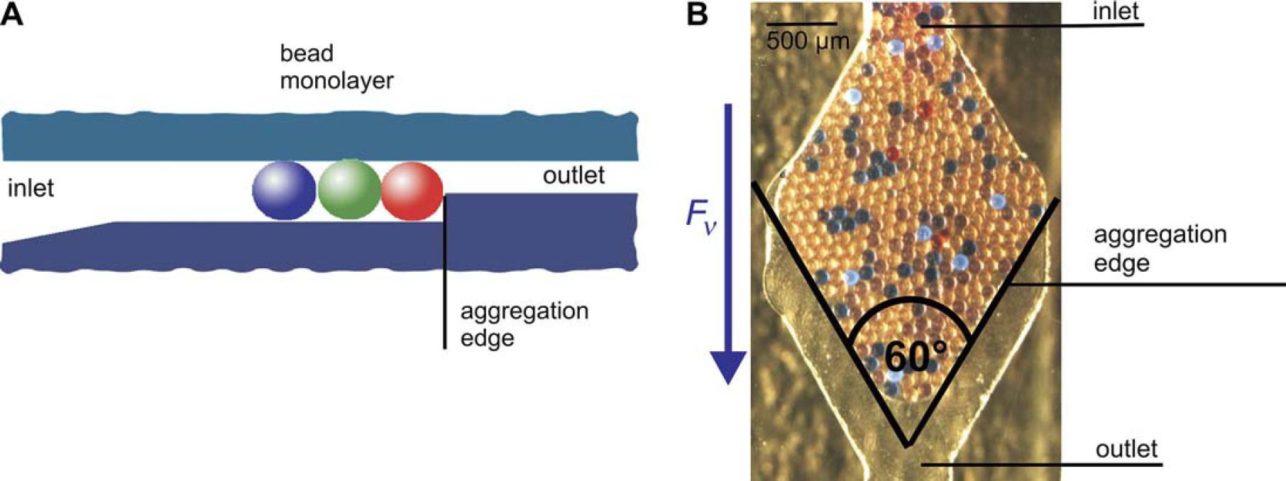
Aggregation of a bead monolayer in the detection chamber. A suspension of beads is driven by the centrifugal force F v. (A) The beads are piled up in the measurement chamber at an aggregation edge. (B) A rhombus-like aggregation chamber with an aperture angle of 60° fosters hexagonal aggregation patterns, which lead to the highest package density.
By spinning of the disk, centrifugal forces F v control flow rates and thus incubation times at high accuracy to carry out the standard steps of a fluorescence immunoassay, that is, the delivery of the sample, detection of antibodies, and washing. In a two-step read-out procedure 41 using the same camera and LED, a fluorescence image of the bead-incorporated QDs is first captured while using a long pass filter. An image processor localizes the beads and identifies their respective color tag in a (statistically) very reliable manner. In the second step, the specific antigen-antibody binding on the bead surface is measured via the mean fluorescence intensity of the FluoSphereTM-labeled detection antibodies, which are spectrally selected by a band pass filter (Fig. 14). Compared to standard fluorochromes, the FluoSpheresTM provide highly amplified fluorescence intensities in the range of two orders of magnitude.
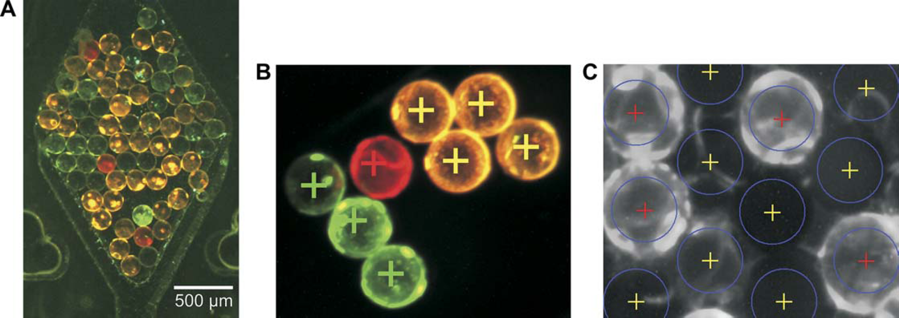
Image of aggregated quantum-dot (QD) beads and image processing. (A) Detection chamber with three types of QD-labeled beads. (B) Results of the first image processing routine to identify the bead center and the bead tag (color ID). First, the center of the beads is localized. Then, the color values of all pixels within a circle around the bead center are compared to a template of set values of the QD types and the beads are assigned to a color ID. (C) The assay results are measured by averaging the fluorescence signal within a circle around the bead center.
To demonstrate the feasibility of a multiplexed disk-based fluorescence immunoassay with the QD-encoded beads, a dilution series is run. It starts from standard human serum (Paul Ehrlich Institute) containing a known concentration of Hepatitis-A antibodies as target protein (Fig. 12). The measured curve (Fig. 15) clearly allows to distinguish the state of protection by Hepatitis-A vaccination (10 international units per ml 80 ).
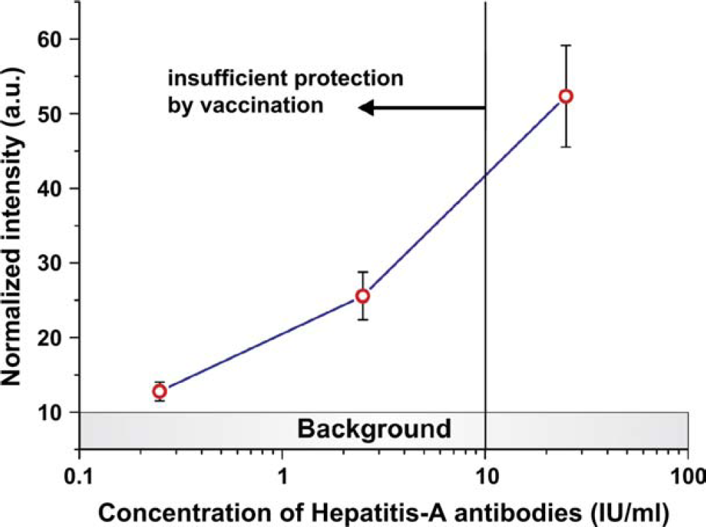
Applying the read-out procedure, we obtain our pilot Hepatitis-A assay curve, which clearly allows to determine the state of protection by Hepatitis-A vaccination (limit at 10 international units/ml).
Development Platform
To rapidly arrive at custom-tailored applications, we also established a backend process development platform, comprising a stroboscopic measurement setup to observe micro-flows on the disk spinning at high frequency, 55 capabilities for CFD-simulation, 34,81 and the prototyping including microstructuring, surface modification, and sealing. The time-critical structuring is accomplished by SU-8/PDMS mastering and subsequent replication in cyclic oletin co-polymer (Topas) by hot-embossing. 54 Ready-to-use disk prototypes are obtained within less than 3 days, thus expediting the iterative design process of functional elements.
Conclusions and Outlook
We developed a comprehensive set of laboratory unit operations for flow control, sedimentation, metering, mixing as well as absorption and multiplexed fluorescence detection schemes, which can be seamlessly integrated into our novel centrifugal microfluidic platform. This opens the way for porting common applications, for example, in the preparation of biological samples, microprocess engineering, and medical diagnostics, to small bench scale platforms. We presented case studies of absorbance and fluorescence immunoassays showing that complete assay protocols can be automated and time-to-results appreciably reduced. Furthermore, the generic rotational symmetry of the disk suggests to place several channels on the same disk that can be used to process a set of protocols sequentially or even simultaneously. Also a multiparameter screening can be performed on the same disk, either channelwise or even in a single channel by multiplexing with color-encoded beads.
Apart from performance issues, the success of microfluidic technologies is tightly linked to a competitive pricing. The contact-free transmission of force as well as the optical detection allows to modularize the system into a reusable “macro” component incorporating all active and moving parts (rotary engine) as well as the detection unit (lasers and spectrophotometer). This way, all “micro” parts can be reduced to their functional essence, that is, passive micro-structures with no moving parts in planar, low aspect ratio architectures, which can be fabricated in a very economic fashion, for example, by industrial scale micromachining techniques such as hot-embossing or injection molding.