
Abstract
In this paper we present the novel adjacent impedance probing (AIP) technique for DNA hybridization detection. In our design, the DNA hybridization site was employed only for the biorecognition event (this site does not necessarily need an underlying conductor surface). A bare adjacent electrode was used for detection of an impedance change. An enzymatic reporter produced the deposition of an insulator on the adjacent electrode. The adjacent impedance probing (AIP) technique is employed to alleviate the low-signal or high-noise problems caused by ssDNA capture probes adsorbed (nonspecifically through non-Au-S binding) on the electrode surface. Data showed that hybridization resulted in a twofold increase in impedance.
Keywords
Introduction
Over the past two decades, the rapidly progressing development of electrochemical DNA biosensors has attracted substantial research efforts. 1 –3 . The expected comparatively high sensitivity of the techniques, coupled with prolific, low-cost manufacturing processes and proposed portable handheld instruments with low power consumption, make such devices potential candidates for the next generation of molecular diagnostic tools. The methods employing attached labels have been studied intensively within the large number of electrochemical detection approaches. Willner and coworkers 4,5 used faradaic impedance spectroscopy to detect DNA hybridization. In their method, the target strand was terminated with a biotin moiety. After hybridization, the avidin/alkaline phosphatase conjugate bound to the biotin increased the charge transfer resistance of a redox probe due to the formation of an insulating layer at the electrode surface. In addition, other strategies such as deposition of metal nanoparticles 6,7 and electroactive reporter molecules 8,9 after hybridization, have been reported.
The methods to immobilize the ssDNA probes, overall, play a key role in the performance of the DNA biosensor. 10 Self-assembled monolayers (SAM) have been shown to be a convenient technique for immobilization of oligonucleotides. 11,12 . The spontaneous adsorption of sulfanylhexyl linker molecules to gold surfaces is a widely accepted method for ssDNA immobilization. The resulting ssDNA layer has been extensively characterized by X-ray photoelectron spectroscopy (XPS), ellipsometry, neutron reflectivity, and electrochemical methods. 13,14 . With this type of surface preparation, thiol-labeled ssDNA spontaneously adsorbs onto the gold surface, both via thiol-gold linkage (specific) and via nonspecific interactions, thus introducing undesirable random orientations of the ssDNA molecules. 13 –15 These random orientations are undesirable because of the resulting nonperfectpolarized membrane on the electrode, which is the main barrier for the implementation of impedance detection. 16,17 Many efforts have been made to improve the immobilization procedures to get a high quality ssDNA SAM on the transducer surfaces. 18 –20
Another route to minimize the problems of nonspecific adsorption of probes on electrode surface is by separating the sensing electrode from the hybridization site. Mirkin et al. 21 designed a pair of sensing electrodes separated with a gap where the capture probes were immobilized. The hybridization occurred between these two electrodes, and Au nanoparticles attached to the target DNA were localized in the gap. The nanoparticles and electrodes were then made into a continuous conducting element by the reduction of silver ions onto the nanoparticles. The conductivity between these two electrodes changed upon the Ag deposition. Paleček et al., 23 Wang et al., 24 and Kizek et al. 25 worked on a new assay method called the “two-surface strategy.” The probes were initially immobilized on the commercially available Dynabeads (surface H) (Dynal Biotech, Oslo, Norway) and hybridized to the target DNA. The Dynabeads are magnetically separated prior to electrochemical detection. A separated detection electrode (DE) was connected with various electrochemical detection schemes. These methods inhibited noise generated from nonspecific capture probe immobilization.
In the current study, a unique method (i.e., adjacent impedance probing) was employed for DNA hybridization detection. Using microfabrication processes, the two-surface concept was proved feasible in the same spatial domain (planar process). For signal detection, we used an “impedance amplifying label” to amplify the signal on the adjacent sensing electrode.
Experimental Section
Materials
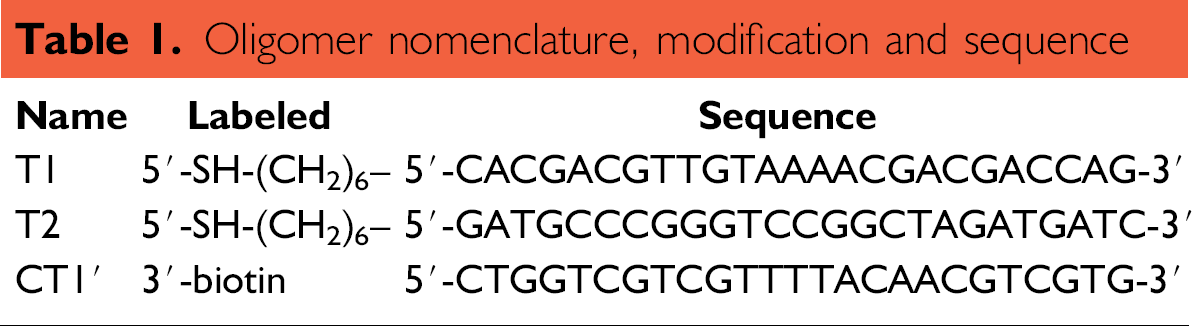
Solutions used in this study were prepared with deionized water (18 MΩ-cm resistivity). All reagents were purchased from Aldrich Chemical (St. Louis, MO) and used as received unless otherwise noted. DNA oligonucleotides were purchased from BioSource Inc. (Camarillo, CA). The two ssDNA probes, T1 and T2, were 25mers and were modified at the 5' end with an alkylthiol modifier for immobilization on Au electrodes. The single-stranded target (CT1) contained fully complementary sequence to the probe T1 and came equipped with a biotin label on the 5' end. The sequences and modifications of each oligonucleotide were listed in Table 1
Oligomer nomenclature, modification and sequence
Electrode and Gold Microspot Preparation
The standard 1 × 3 glass slides were used as the substrate material to fabricate the electrodes. Before electrode patterning, the substrates were first cleaned with the RCA cleaning method (5 parts deionized water, 1 part NH4OH, 1 part H2O2). The dehydration baking was performed in a convection oven at 200 °C for 30 min.
To precisely define the hybridization area, sensing area, and the width of the gap in between, the electrode patterning can be of benefit in a so-called lift-off process by creating an undercut photoresist wall. A thin layer of positive photoresist (Shipley 1827 MicroChem Inc., Newton, MA) was spun at 4000 rpm for 40 s onto the substrate; this was followed by a soft bake at 90 ° C on a hot plate for 2 min. The photoresist was then UV exposed through a patterned iron oxide mask in a Karl-Suss mask aligner (Suss MicroTech Inc., Waterbury center, VT). The positive resist surface was presoaked with an aromatic solvent (e.g., chlorobenzene), dried under a stream of pure nitrogen, and subsequently developed in a MF 319 developer.
Au films were formed by electron beam vapor deposition on resist-patterned substrate. In order to promote adhesion of the gold, a thin Cr adhesion layer (50 nm) was deposited between the Au layer and the glass surface, followed by the e-beam deposition of a 200-nm-thick film of gold. The lift-off process was accomplished by immersing the Au-film-covered chip in acetone, leaving a patterned Au film fixed on the substrate surface.
To preclude the detection perturbation by ssDNA capture probes adsorption onto the sensing electrode, the adjacent electrodes were sheltered via superimposed photoresist patterned by standard photolithography with precise alignment. The uncovered area, hybridization microspot, was employed to immobilize probes in the subsequent step. Figure 1 shows the image of the two-electrode layout. Figure 1a presents the spatial position of hybridization microspot versus adjacent sensing electrode. The gap length between two electrodes was 10 μm, and Figure 1b shows the magnified image of one edge of the electrode layout. The peripheral transparent photoresist layer, flecked with dark spots, was patterned to entirely cover the adjacent electrode.
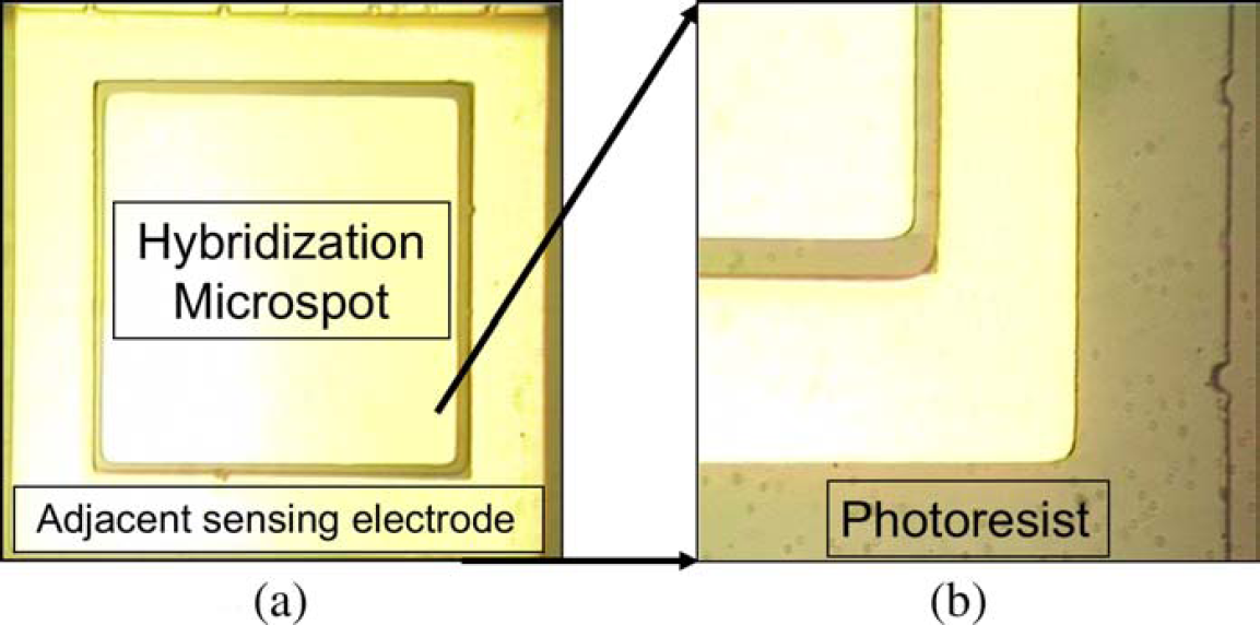
Images of the electrode design of adjacent impedance probing (AIP). (a) Spatial position of hybridization microspot versus adjacent sensing electrode. The gap length between hybridization microspot and adjacent sensing electrodes is 10 μm. (b) The magnified image of one edge of the electrode layout. The peripheral transparent photoresist layer, flecked with dark spots, is aligned to entirely cover the adjacent electrode and encompass the whole electrode area.
DNA Probes Immobilization and Target Hybridization
For immobilization of the probe DNA (SH-ssDNAs), a 20 μl solution of 1 μM of oligonucleotide probes in a 1.0 M KH2PO4 was pipetted onto the electrode. For the thiolated ssDNA self-assembled monolayers to form, we allowed the reaction to remain at room temperature for 15 h or more. At the end of the incubation, a spray of acetone was employed to strip out the photoresist covered on the adjacent sensing electrode. The surfaces were immediately rinsed with deionized water and blow-dried under a stream of pure nitrogen.
Hybridization was performed by spotting the CT1 solution (1 μM DNA in 1X PBS buffer; 0.01 M phosphate buffered saline, NaCl 0.138 M, pH 7.4 at 25 °C) on the electrode surfaces at room temperature. After 4 h, the electrodes were rinsed with the hybridization buffer (1X PBS) and kept wet at room temperature for subsequent enzymatic reactions.
Enzymatic Reaction to Form Precipitate on the Adjacent Sensing Electrode
We used a commercially available enzyme-labeled fluorescence (ELF 97) signal detection kit (Molecular Probes, Eugene OR) 26 as a tool for impedance amplification in the probing stage. All reaction steps and the amount of reactants followed the instructions in the manufacturer's protocol unless otherwise noted. Briefly, after hybridization, the electrodes were rinsed with the hybridization buffer. Then, the streptavidin-alkaline phosphatase conjugates were bound to the biotinylated target DNA. Next, the ELF 97 substrate was added. The reaction yielded a precipitate, on the adjacent impedance electrode, by enzymatic cleavage of ELF 97 phosphatase substrate, and can be verified visually by UV light-excited fluorescence microscopy. The precipitate fluorescence is an intense yellow-green color with maximal excitation and emission wavelengths at ∼360 nm and ∼530 nm, respectively. The substrates were incubated for 1 h at room temperature and then the impedance measurements were performed.
Impedance Measurements
A three-electrode electrochemical system was used for electrochemical impedance spectroscopy (EIS) measurements. A saturated calomel electrode (SCE) reference electrode and a Pt auxiliary electrode were chosen. The working electrode was connected to the contact pad of each electrode fabricated on the glass substrate. All electrochemical measurements were performed using an electrochemical impedance spectroscopy potentiostat from Gamry Inc. (Warminster, PA). The buffer solution for all the impedance measurements was a 10 mM [Fe(CN)6]3-/4- in 1X PBS buffer. The solution was purged with nitrogen for 15 min to remove dissolved oxygen before measurements. The impedance spectra for the bare Au adjacent electrode and the enzymatic reaction modified adjacent electrode (precipitates on Au) were measured with the potentiostat from 100 KHz down to 1 Hz at a sampling rate of 10 points/decade. An ac voltage of 50 mV rms versus the reference electrode was chosen.
Results and Discussion
DNA Hybridization Detection by Adjacent Impedance Probing Mechanism
Figure 2 depicts the configuration of the DNA detection via adjacent impedance probing (AIP). The thiolated oligonucleotide probes were assembled on the Au hybridization microspot as described above. Noncomplementary thiolate oligonucleotide probes were likewise deposited on the other Au hybridization microspot as a control. The resulting functionalized hybridization microspots were then treated with biotinylated target DNA to yield either the biotin/dsDNA in complementary case or ssDNA in non-complementary case. The whole systems were further treated with streptavidin/alkaline phosphatase conjugate. Subsequent association of the enzyme-catalyzed hydrolysis of a phosphatase substrate led to the formation of an insoluble precipitate on the adjacent sensing electrode. The formation of the enzymatic reaction to produce the precipitates provided not only the signal for the hybridization events but also an amplification process for the detection of the target DNA. Figure 3 shows fluorescence images of precipitates on microspot surfaces with hybridization (Fig. 3a) and without hybridization (Fig. 3b). There were two observations. First, the dispersion of precipitate covered the adjacent sensing electrode. Second, the lack of precipitation for noncomplementary samples (Fig. 3b) indicated that there was low nonspecific binding of either biotinlabeled target DNA or streptavidin/alkaline phosphatase conjugate. The impedance signal was amplified from precipitation and had less background noise than work carried out in single electrode systems where hybridization was done on the impedance-measuring electrodes. 27
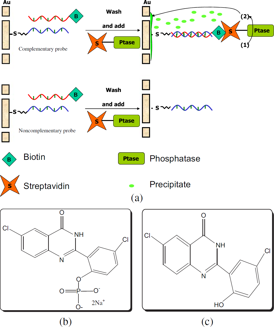
(a) Mechanism of the DNA detection-employed adjacent impedance probing (AIP) with impedance amplifying labels (IAL). First, the DNA probes are immobilized on the hybridization microspot. The biotin-labeled target DNA was hybridized to the probes. In the case of the complementary probe, the biotin was brought to the microspot through the event of hybridization. Then, the streptavidin-alkaline phosphatase conjugates were bound to the biotin and located the enzyme on the site of hybridization. Next, the ELF 97 substrate (b) was added. The reaction yielded the precipitate (c), on the adjacent impedance electrode, by enzymatic cleavage of ELF 97 phosphatase substrate. (b,c) Molecular formula of ELF 97 phosphatase substrate (b) and alcohol precipitate (c).
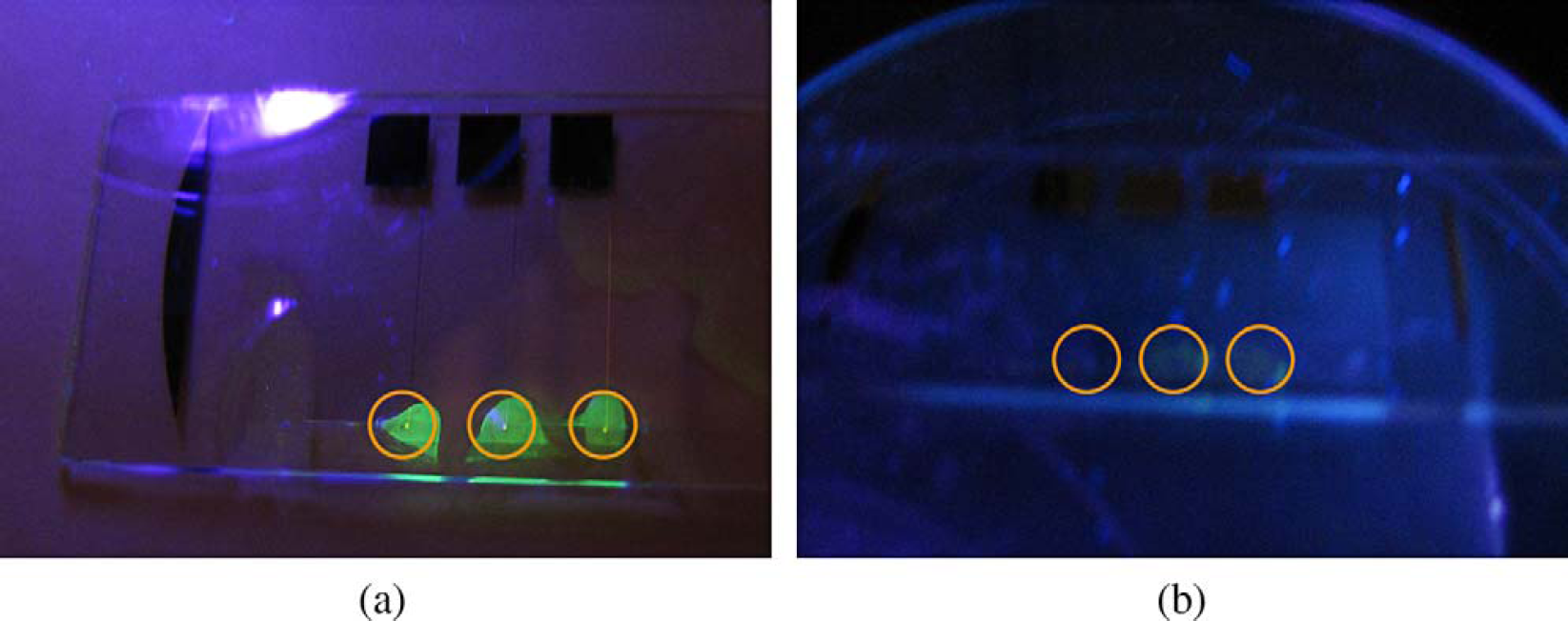
Fluorescence images of precipitates on microspot surfaces (a) with hybridization, and (b) without hybridization. The gold circles indicate the positions of electrodes.
Impedance Measurements for DNA Hybridization Sensing
The charge transfer resistance was expected to change upon surface modifications induced by binding of molecules on the electrode surface. Figure 4 showed the results of impedance measurements made on bare gold sensing electrodes and on the same electrodes after precipitate deposition. Figure 4a shows the impedance data of the complementary samples presented as Bode plot, and Figure 4b gives the impedance data for noncomplementary samples also presented as Bode plot. At medium frequency, for example 158 Hz, a noticeable increase of impedance modulus appeared in the Bode plot (Fig. 4a) sensing of the precipitate deposition. At the same frequency, for noncomplementary sample measurement, there was an indistinguishable change of impedance modulus in the Bode plot (Fig. 4b). The ratio of impedance, increased for the complementary sample, was around twofold (1.9 ± 0.19, n = 8 with one standard division) compared to the 1.1 times (1.1 ± 0.1, n = 8 with one standard division) for noncomplementary cases. In our previous work, 27 the signal increased 1.6 times with the same amplification technique exerted to solid electrode without an adjacent electrode detection scheme, but in the same experiments, the noncomplementary samples had 1.3 times impedance increased. Figure 4(c) shows the faradaic impedance spectroscopy for four scenarios presented in the form of a Nyquist plot (Zreal vs. -Zimag). The comparison results indicate that partitioning the sensing electrode from the hybridization site, as employed in AIP, eliminated the noise induced by nonperfect polarization of self-assembled ssDNA, and thus increased the signal-to-noise ratio. In the Nyquist plot (Fig. 4c), the semicircle radius of specific samples after hybridization/precipitation increased. This was caused by insoluble precipitate blocking the route for charge transfer, and therefore, the resistance was increased.
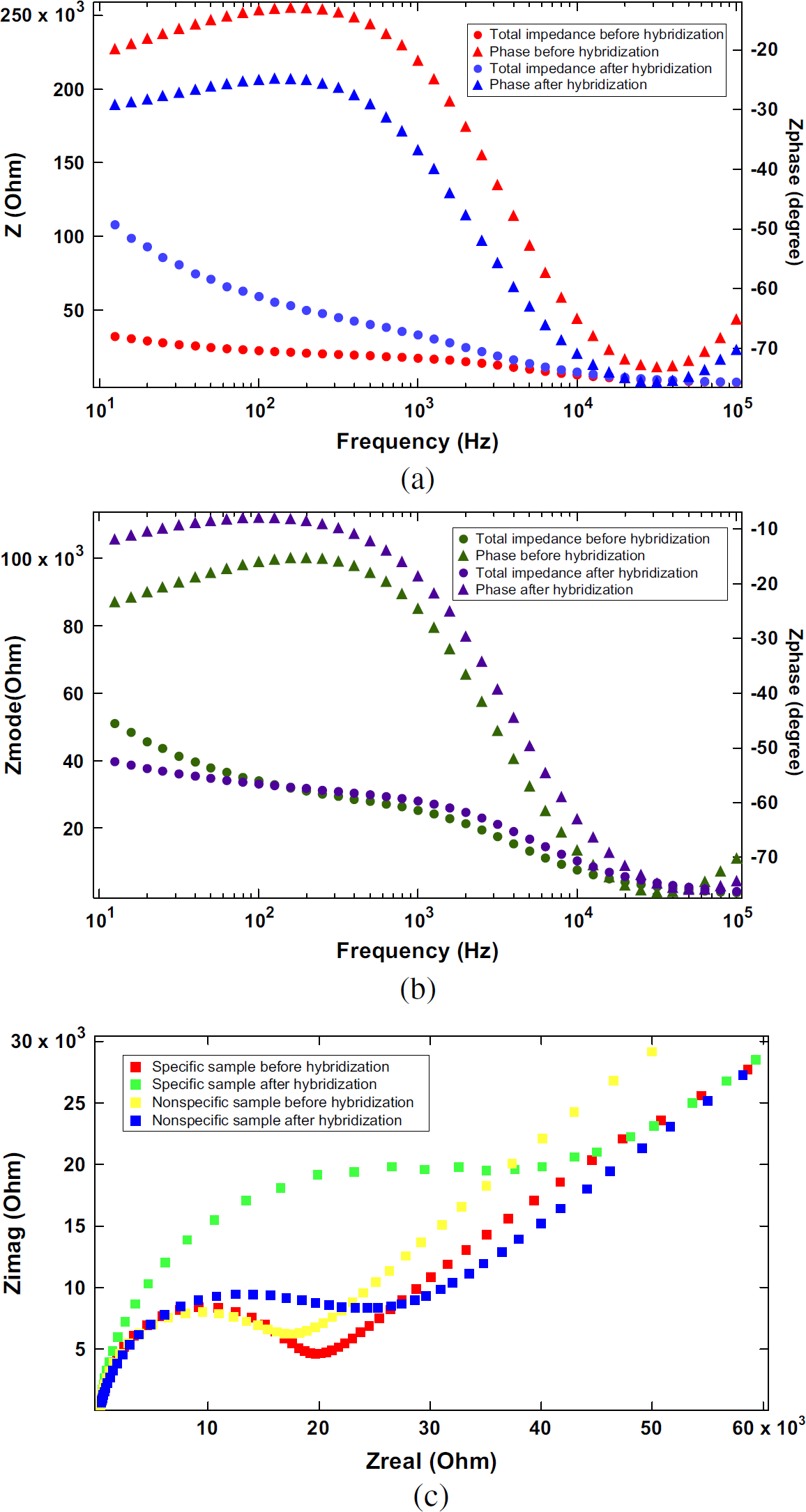
The results of impedance measurements made on bare gold sensing electrodes and on the same electrodes after precipitate deposition. (a) The impedance data of the complementary samples presented as Bode plot. (b) The impedance data for noncomplementary samples also presented as Bode plot. (c) Nyquist plot of data in (a) and (b).
Conclusions
In this study, we fabricated a novel DNA biosensor based on adjacent impedance probing technique. Employing this biosensor, upon DNA hybridization and subsequent deposition of the enzymatic reaction product, we found significant improvement on the signal of DNA hybridization detection. Our data showed the enhancement of the hybridization signal by approximately twofold. In conclusion, the novel detection concepts presented here are generic. Further studies, such as lowest detection limitation, optimal enzymatic reaction and detection time, and desirable electrode size with adequate manufacturing processes, are required before any practical applications.