
Abstract
Most of the scheduling software and instrument integration frameworks are written in Visual Basic, C/C++, or the LabView programming environment. A lot of these frameworks are proprietary tools of instrument vendors and are used by these companies during system integration of their instruments. In addition to the closed architecture of these products, the scheduler choice is very limited. ReTiSoft Inc. has created a suite of software products that address these problems.
In this article we would like to introduce ReTiSoft's open-architecture framework for instrument integration, a hybrid scheduler (static and dynamic) and a Web-enabled interface to the automated system. In addition to ReTiSoft's integration framework (Genera) and the hybrid-scheduling software (Supra), we recently developed a Web-enabled application that allows scientists to log onto the automated system remotely, set up and run assays, examine and analyze the data produced during the experiment. The software is called DataPilot and is comprised of a high-performance database engine and the Apache Web server.
In unison with Genera's and Supra's open-architecture approach, DataPilot can be modified and customized by system integrators to suit their specific application needs. The application serves as a data repository and adheres to guidelines presented by the Code of Federal Regulations for electronic records and electronic signatures; the guidelines are known as 21 CFR Part 11.
This article provides an architectural overview of our software products and justifies its merits in comparison to other technologies commonly used in laboratories. We describe our Genera integration framework, give an overview of our scheduling algorithms, describe a Web-enabled data-tracking software and the enzyme-linked immunosorbent assay (ELISA assay), and describe different methods of automated system validation using our software. We also offer some conclusions.
Keywords
Introduction
When automated systems are purchased by laboratories, two common approaches prevail. The purchasing companies either buy turnkey solutions from system integrators or purchase the equipment directly from the instrument vendors and do the system integration in-house. Most of the turnkey systems are custom written and not flexible, thus making it difficult to reconfigure or add new equipment. To alleviate this problem, companies choose to integrate systems in-house. This approach provides them with greater flexibility; however, they usually struggle with maintenance and upgrades of these in-house systems.
Also, most of the scheduling software and instrument integration frameworks are written in Visual Basic, C/C++, or the LabView programming environment. Visual Basic is a good tool for quick prototyping, but it fails to address most of the scheduling needs of automated systems. C/C++ are lower level languages that make it difficult to program and maintain the software. They also lack the scheduling constructs that are required in some applications. The LabView programming environment also is widely used in laboratories. We found LabView to be a good tool for developing simple data acquisition applications; however, it was difficult to use it to control complex automated systems.
At ReTiSoft, we created a suite of software products that address these problems. Now, the laboratories could purchase the most suitable equipment from instrument vendors and use our Genera integration framework along with the Supra scheduler to integrate the systems internally. Because both of these products provide interfaces for instrument integration and software customization, the automated systems can be easily reconfigured.
All of the ReTiSoft software products were developed in Java. At the beginning of the project, we were hesitant with our choice of the programming language because of the high popularity of Visual Basic in the laboratory field. However, the possibility of porting our Java applications to Linux, Sun Solaris, and Macintosh platforms, combined with the Sun Microsystems open-architecture approach to the development and formulation of Java, outweighed the fact that Visual Basic is still the prevalent development language in laboratories. The object-oriented nature of Java, its security features, ease of programming, maintenance, and debugging were other reasons that we chose it as the underlying development language for Genera and Supra.
Most of the instrument vendors provide an interface to their instruments through ActiveX libraries. To elevate the problem of interfacing Java with ActiveX components, we purchased JIntegra software that allows us to bridge the Java language with ActiveX dynamic link libraries, OCX containers, or executable programs.
Another drawback of the current integration frameworks is their limited scheduling capabilities. The schedulers available on the market are either static or dynamic. Our Supra software implements a true hybrid scheduler, in which the user has a choice of using the appropriate scheduling algorithm, either static or dynamic.
Overview of Software Architecture
To simplify the integration of automated systems, our software products divide this task into the following steps:
Connection to physical instruments with our integration framework (Genera).
Creation and validation of protocols with our hybrid scheduler (Supra).
Additional validation of protocols with our 3-D simulation tool (SimView).
Customization of protocols for end-users within our Web-enabled LIMS (DataPilot).
Our software architecture conforms to the message-based model, which allows new listeners to be added easily to the sending module. This approach works very well in lab automation environments in which new listening modules must be easily added for data acquisition, monitoring, or logging purposes. A diagram of a message-based model is shown in Fig. 1.
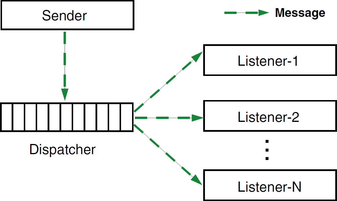
Message-based model.
Fig. 2 shows a high-level architecture and interactions between different software components. Genera is a central component in the automated system; that is, it controls all the software and hardware modules. When Genera relays a command to a physical instrument, the same command is relayed to all the registered listeners of the Genera software. In our diagram, the 3-D simulation software (SimView) is a listener. When a response or an alarm is received from the physical instrument, the response or alarm is also propagated to all the listening modules.
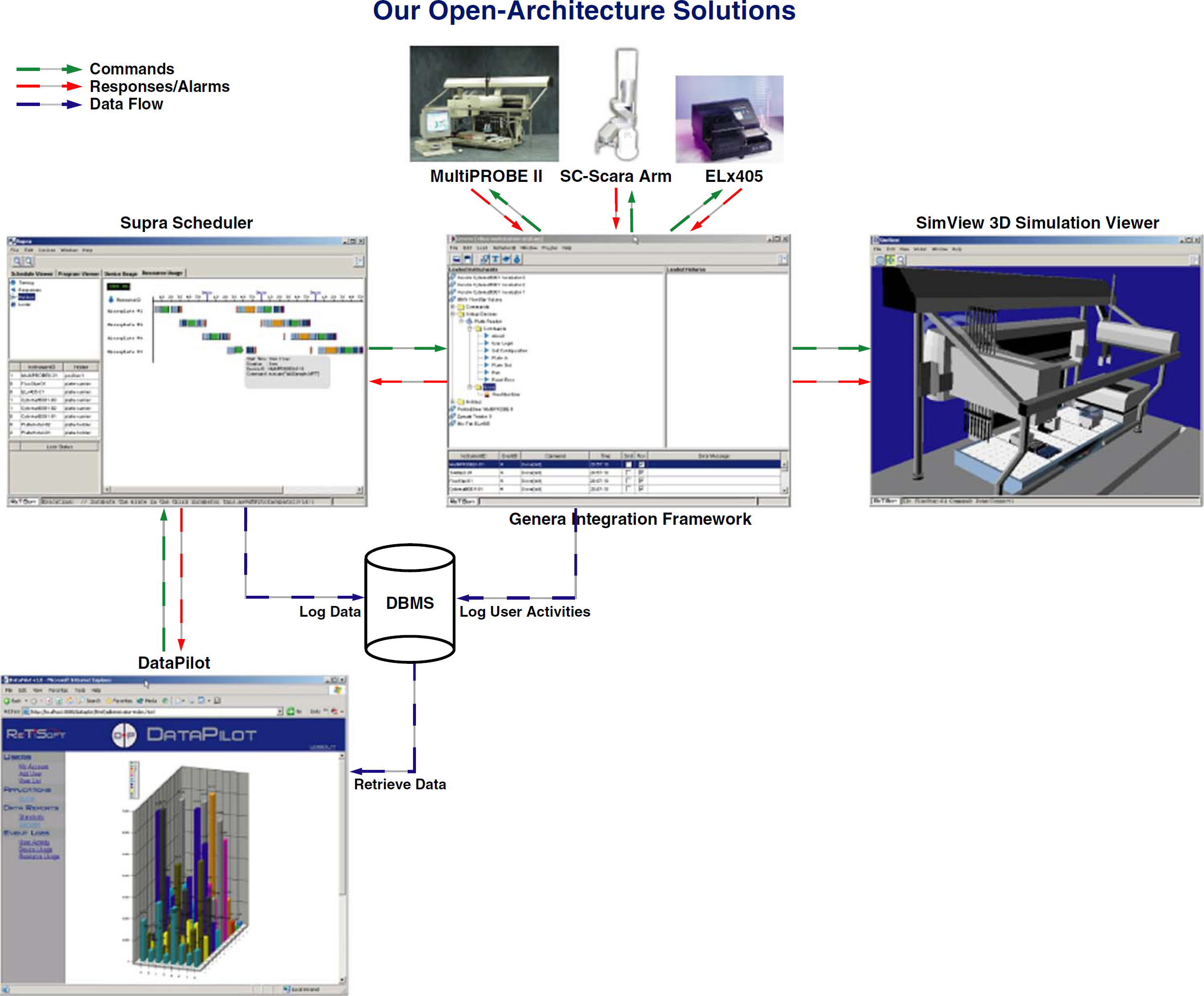
Software architecture.
Integration Framework: Genera
To simplify the integration of different, heterogeneous instruments, we created an integration framework, called Genera. The framework is written in pure Java and contains the following features:
EXtensible Markup Language (XML)-driven instrument definition, which provides a well-defined description of instrument capabilities, that is, instrument properties along with their available commands.
Automatic generation of release notes for each instrument.
Automatic generation of GUI components for each instrument.
Logs of all the instrument commands, response messages, and instrument errors.
Built-in support for reactive scheduling.
Message-based communication model between the framework and other software modules.
21 CFR Part11 compliance.
Open software architecture.
The Genera integration framework is based on an open and extensible architecture that allows the user to control and monitor any instrument. Because of the generic nature of its architecture, the instruments may use different communication technologies and protocols. The framework can also be seamlessly integrated with third-party applications, such as LIMS, spreadsheets, data tracking, or data analysis software. Fig. 3 depicts different layers of the Genera framework. To learn how to integrate different instruments within the framework, the reader should refer to the Genera Integration Guide. 1
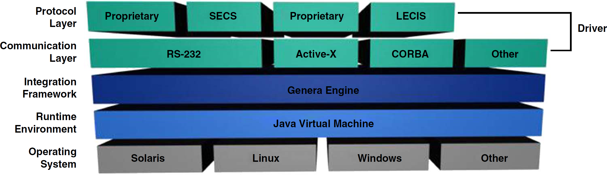
Genera software layers.
Operating system. Genera application is entirely written in Java, and it runs on Sun Solaris, Linux, Microsoft Windows, and other operating systems that contain Java Virtual Machine.
Runtime environment. To run our integration framework, Java Runtime Environment (JRE) version 1.4.2 or later must be installed.
Integration framework. Genera engine along with its underlying libraries allows easy integration of diversified laboratory instruments. Instrument properties are described by well-defined XML files, which can also serve as instrument interface documentation.
Driver. Genera driver is a pluggable software component that sends commands to the laboratory instrument and listens for responses and alarms coming from the instrument. The driver is comprised of two software layers:
the communication layer determines what type of communication media the instrument is using, such as RS-232 port, Active-X, DDE, CORBA, TCP-IP sockets, XML RPC, SOAP, and so on.
the protocol layer determines the structure of messages and handshaking that occurs between the driver and the instrument. The driver may either implement a standardized protocol, such as SECS 2 (SECS is a coordinated pair of standards for the semiconductor industry that define an RS-232 communications interface between semiconductor equipment and a host), LECIS 3 (LECIS defines a remote control interface between laboratory instruments and a host; it was initially defined by the American Society for Testing and Materials), or proprietary protocols provided by instrument vendors.
Hybrid Scheduler: Supra
During the development of the Supra scheduler, we wanted to address the loopholes of the existing scheduling software products. Although some products provide the user with very sophisticated static schedulers that are appropriate for HTS applications and time constraint assays, their error recovery features are poor. The currently available dynamic schedulers concentrate on the error recovery; however, they do not perform well in time-driven applications. To address these scheduling issues, we created a hybrid scheduler, which allows the user to choose either static or dynamic execution algorithm. The two scheduling approaches will be described in more detail in the following sections.
Static Scheduling
When the static scheduler is selected, the automated system activities must be estimated first before a schedule is executed. During the estimation stage, the order of activities (tasks) is optimized and laid out on the timeline. When the schedule executes, all the tasks are dispatched according to their start times. The schedule optimization algorithms were based on a scheduling problem in a tightly-coupled serial production line with deterministic processing times. 4 In the following sections, we will describe our schedule optimization approach along with its benefits and drawbacks.
For the schedule optimization to take effect, the activities in the system must occur in parallel. To allow for the parallel processing of tasks, we introduced the parallel construct within our dynamic scheduling language (DSL). Let us define a sample scheduling problem that uses two resources (e.g., microplates), three workstations (e.g., plate hotels, incubators, plate washers), and a robotic arm that tends the resources. Also see Table 1 for notation.
Notation for example 1
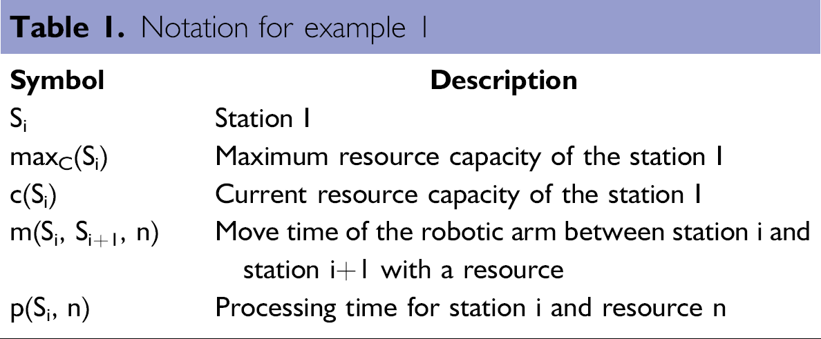
Example 1.
In the above example, the stations S1 and S3 are input and output carousels that hold five microplates. The station S2 could act as an incubator, plate washer, or liquid handler. It can hold two microplates, and its processing time is 5 seconds. To simplify the example, we will use two microplates that are initially placed on the input carousel. The following is a sequence of steps for each microplate:
Robotic arm fetches a microplate from the input carousel (S1).
Robotic arm deposits the microplate on S2.
Station S2 processes the microplate for 5 seconds.
Robotic arm fetches the microplate from S2.
Robotic arm deposits the microplate on the output carousel (S3).
The corresponding static DSL program that processes two microplates in parallel will look as follows:
The static scheduling engine during the estimation phase has a choice of two execution paths depicted in Fig. 4. When the left execution path is taken, the robotic arm does not waste any time waiting for the processing on station S2 to finish, and as a result, the final schedule is more optimal. After generating all the possible execution paths, our static scheduler chooses a valid and optimal execution path and lays out its tasks on the timeline as depicted in Fig. 5. When the schedule executes, all the tasks are dispatched according to their start times.
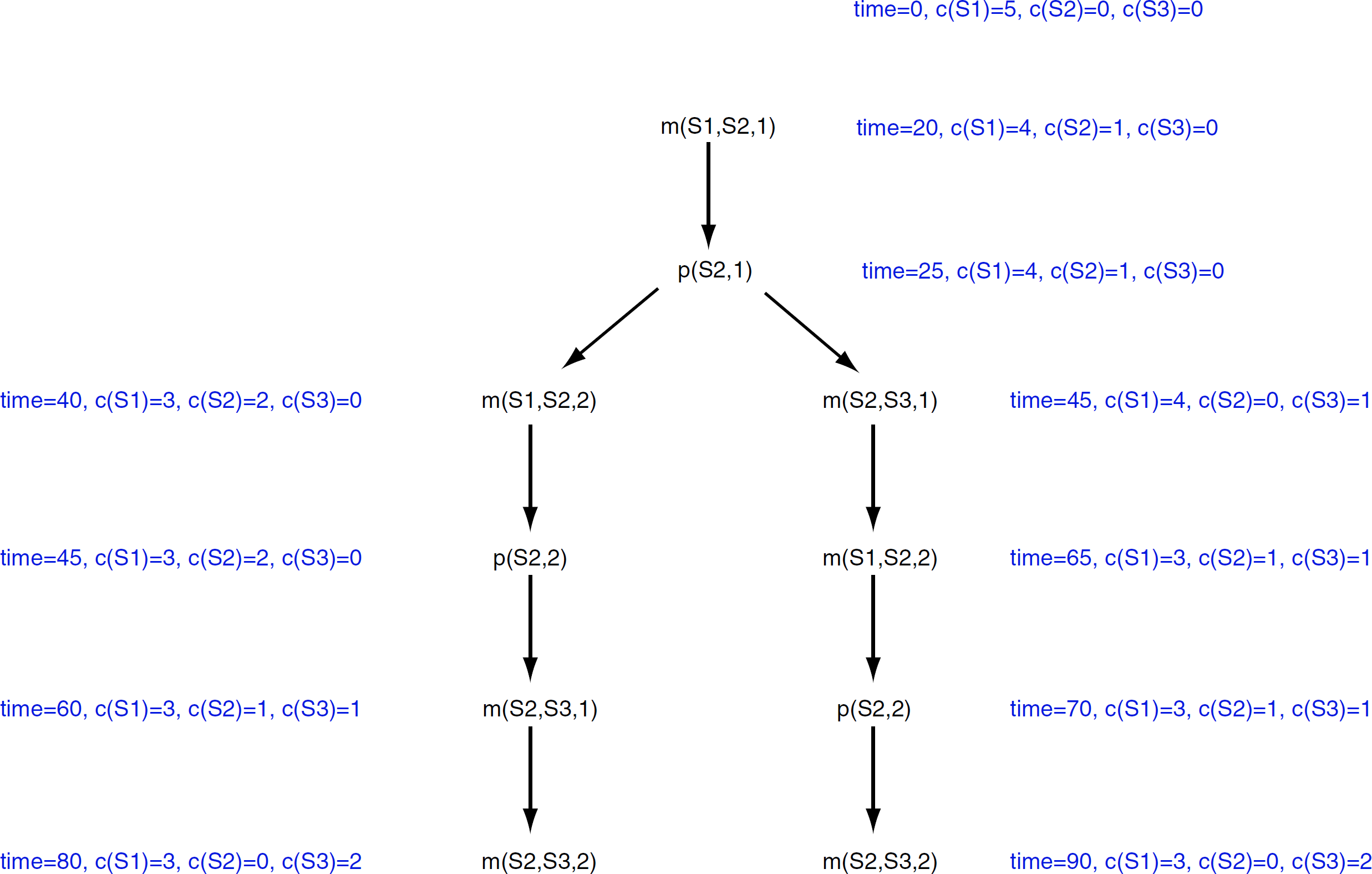
Schedule estimation paths.
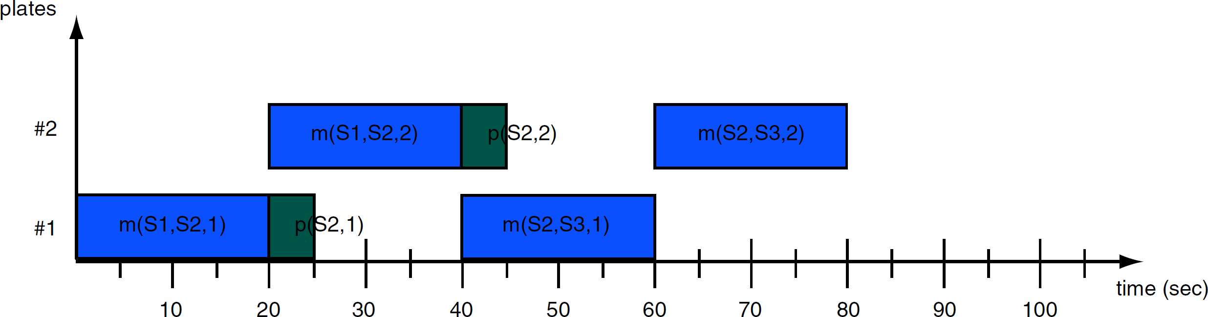
Schedule timechart.
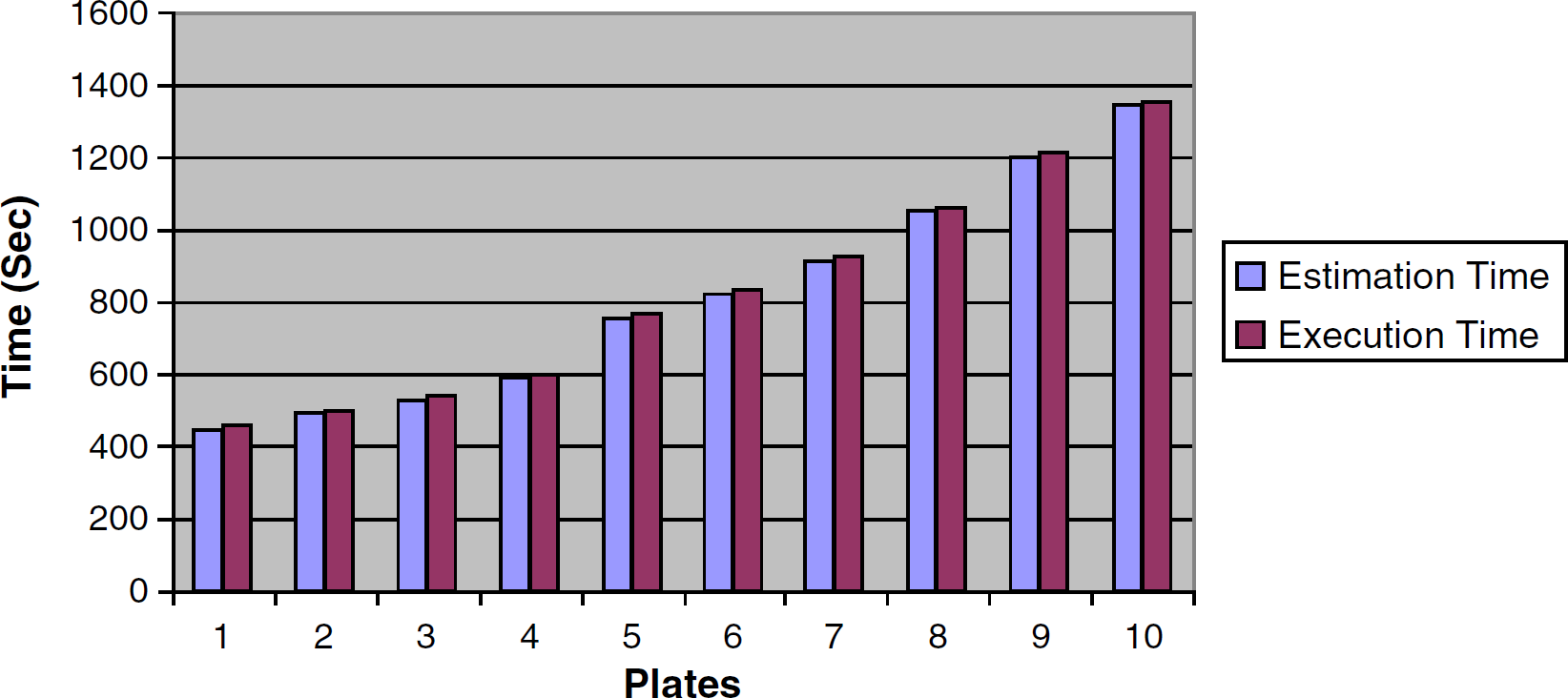
Static schedule times.
The other advantage of this approach is deadlock-free schedules. Because the estimation phase is carried out before the execution phase, the estimation algorithm will always find a suitable execution path for any given assay. The estimated static schedule can also yield better results than its dynamic counterpart, especially for a larger number of microplates. In our sample assay, the dynamic scheduler was not able to find an execution path for more than seven microplates that ran in parallel. However, this shortcoming could be overcome by queuing consecutive batches of microplates. That is, if the user would like to process 70 microplates during the run, he or she would queue 10 batches of seven microplates for the dynamic scheduler.
Because of the inherent nature of static schedulers, that is, that the schedule is estimated and optimized ahead of its run, error recovery is very difficult. As a side effect of this, the timing of each task must be specified accurately to avoid discrepancies between the estimation and execution phase. In other words, the estimated time of robotic arm movements and processing time on each station must correspond to the actual timing values. If tasks miss their deadlines, non-disruptive rescheduling algorithms 5 could be used; however, they might not preserve the assay timing constraints.
Because of the time-driven nature of static schedulers, it is also hard to make run-time decisions after the estimation phase of the schedule. The static schedulers are rigid and are not suitable for making run-time decisions on the basis of the current state of the assay or equipment availability.
Dynamic Scheduling
Our dynamic scheduler runs by examining the available instruments and system resources. Because of its event-driven nature, the dynamic scheduler can make run-time decisions during its execution. When it is selected, the automated system activities can be executed without being estimated first. In the following sections, we will describe our dynamic scheduler algorithm, along with its benefits and drawbacks.
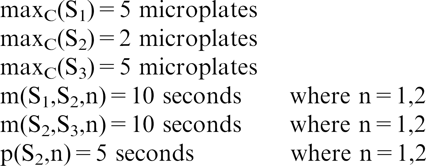
To describe the dynamic scheduling algorithm, we will use the same scheduling problem as in the static scheduling example, example 1. Please see Table 2 for notation. Notice that the move time of the robotic arm between station i and station i+1 with a resource, as well as the processing time for station i and resource n, do not have to be specified for the dynamic scheduler. In other words, the dynamic scheduler does not need the timing constraints to execute.
Notation for example 2
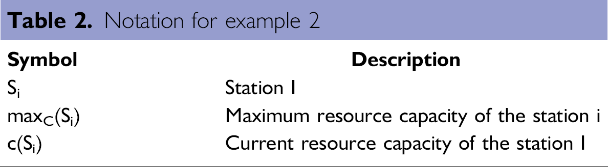
Example 2.
maxC(S1) = 5 microplates
maxC(S2) = 2 microplates
maxC(S3) = 5 microplates
The corresponding dynamic DSL program that processes two microplates in parallel will look as follows:
The dynamic scheduling engine, during its execution phase, uses a greedy algorithm, 6 in which the engine assumes that the optimal execution path is a series of locally optimized and valid steps. When the schedule executes, all of the tasks are dispatched according to real-time events (that is, task completes its execution; station error or resource was added or removed from the station) which occur in the system.
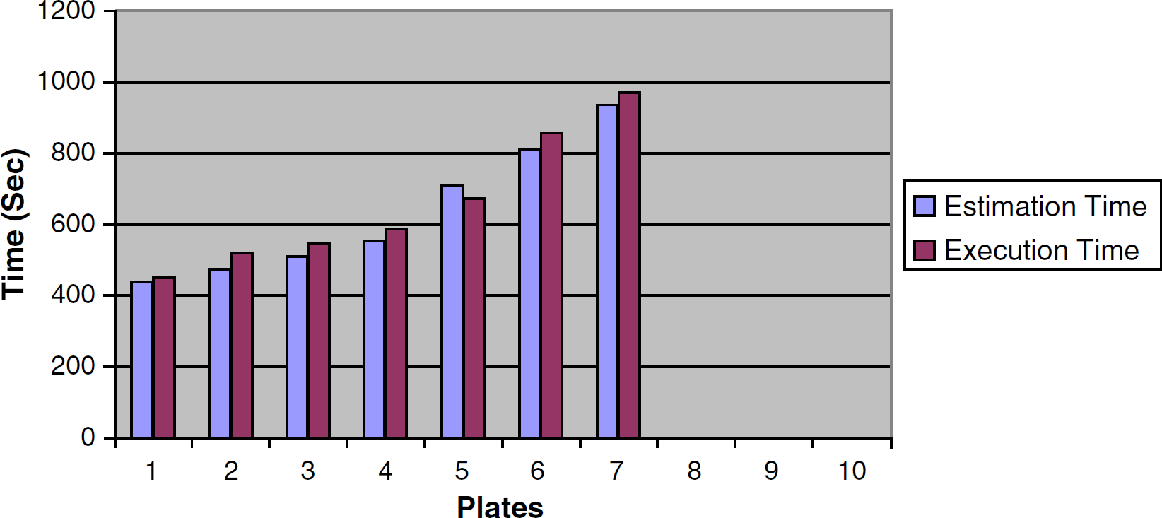
Dynamic schedule times.
The dynamic scheduler also does not guarantee deadlock-free schedules because of its local optimization heuristics. Also, during the run, the dynamic scheduler might choose to take a different path compared with its estimation phase. In other words, the estimation and execution paths are decoupled and could be different during the actual run.
The dynamic scheduler is much more flexible when it comes to error recovery. Because its execution is based on real-time events, the scheduler can adopt to errors or feedback from an input source (e.g., database, property files, user prompts). Also, in some assays, the timing of tasks cannot be determined. In these situations, the dynamic scheduler would be the only choice for the user. If tasks miss their deadlines, the scheduling algorithm will push back all the other tasks without the need to reschedule or stop the assay.
Web-Enabled Interface to the Automated System: DataPilot
In addition to running applications (i.e., DSL programs) within the Supra scheduler, the users can run these applications within DataPilot. Each application in the DataPilot has an associated set of physical instruments that comprise an automated system. These instruments must first be initialized before the application can be estimated or executed. The DataPilot applications can be written and customized by third-party system integrators to provide Web-enabled, custom, and user-friendly solutions for automating systems in laboratories.
After the user specifies the assay parameters and starts executing it, a DSL program is dynamically created and uploaded onto the Supra server and then executed. In other words, the DataPilot application generates a DSL program that is dynamically based on the parameters that are entered by the end user in the provided input fields of the HTML interface. By automatically generating DSL programs, we decoupled the complexity and intricacy of scheduling an automated system from the end-user interface for scientists.
Because the automated system could be run remotely from the Web browser, several security features were implemented to prevent unauthorized system use. The following security features are included in the DataPilot application:
User login prompt.
User privileges that allow or prevent users to run the applications remotely or delete records from the underlying database management system.
Exclusive usage of the automated system; that is, when one user starts running the system, everybody else cannot use it until the system completes its processing.
The following paragraphs provide an example of a custom ELISA system that we created for one of our clients. The ELISA is a tool that is used for the detection of small quantities of a target compound in sample solutions. After automating the ELISA protocol to enable detection of thousands of target compounds each day, we created a Webenabled interface for scientists to use the automated system. The following is a list of the hardware instruments that were used in the assay.
Three Kendro Cytomat5001 incubators that were used for three incubation sequences.
PerkinElmer MultiPROBEII liquid handler that was used for adding sample, substrate, conjugate, and stop solutions.
BMG FluoStar Galaxy microplate reader.
BioTek ELx405 microplate washer.
Zymark Twister II robotic arm that was used as a microplate tending instrument.
To provide the high-throughput capabilities for the fully automated ELISA system, we divided the experiment into basic automation steps:
Adding samples to the wells of the microplate.
Incubating the microplate at 37°C for 60 seconds (with 30% time tolerance).
Washing away the contents of the microplate wells.
Adding conjugate to the wells of the microplate.
Incubating the microplate at 30°C for 120 seconds (with 30% time tolerance).
Washing away the contents of the microplate wells.
Adding substrate to the wells of the microplate.
Incubating the microplate at 32°C for 75 seconds (with 30% time tolerance).
Adding stop solution to the wells of the microplate.
Reading the microplate to determine the amount of target solution in the sample.
On the basis of the ELISA steps, we designed a custom HTML interface (see Fig. 8) and integrated DataPilot with the Genera and Supra server. After the scientist enters the required parameters by using the HTML interface and starts the execution of the protocol, a DSL program is dynamically created and uploaded onto the Supra server and then executed.
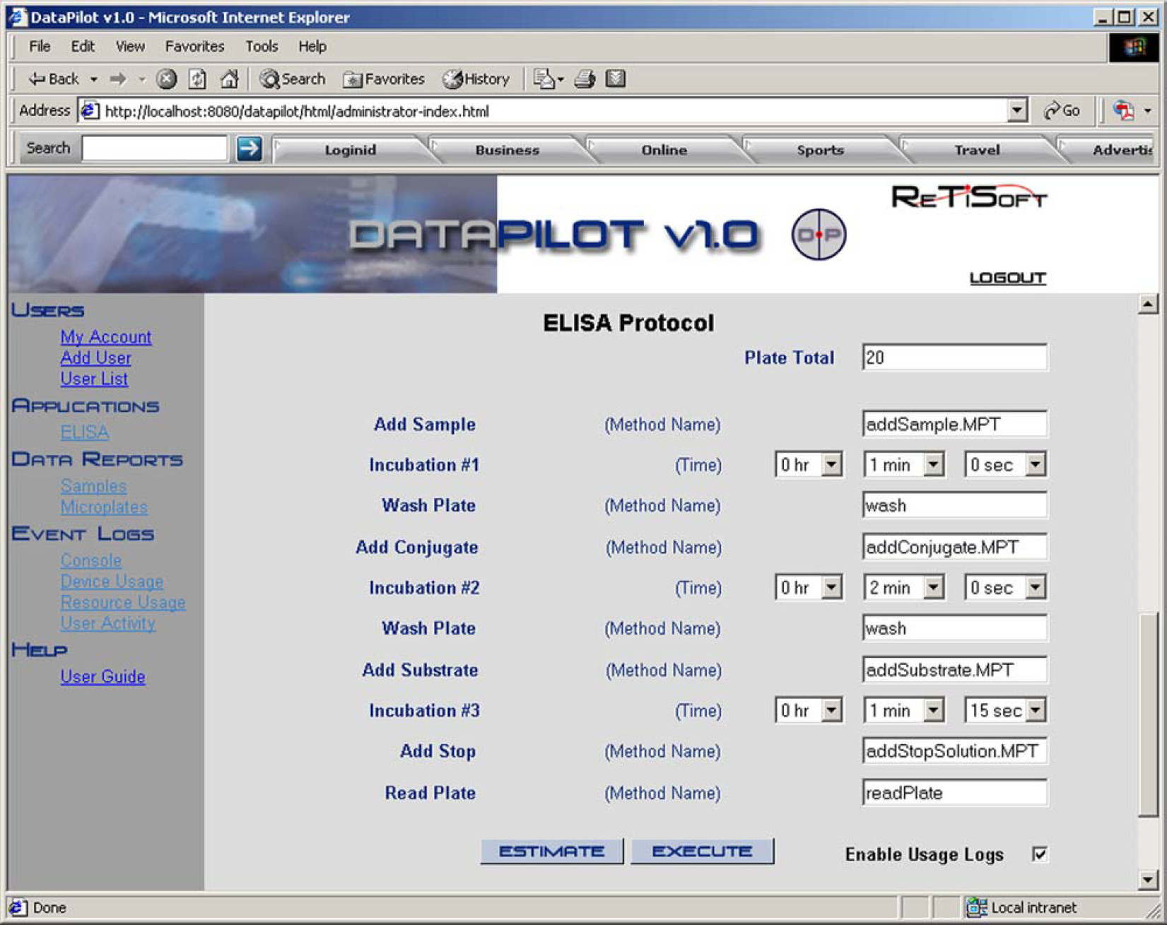
ELISA protocol.
The Supra server also stores all the data (e.g., microplate identifiers, microplate hierarchy, and microplate readings) that have been gathered during the run of an automated system in the database system. The DataPilot application in turn allows the user to view and analyze the data remotely and store it on their personal computers. Several viewing graphs are available.
Automated System Validation
Although current bespoke systems are already validated and tested when delivered to a client site, when they are reconfigured, revalidation and retesting is very cumbersome. Internally built automated systems also require extensive validation each time that they are integrated, which is very costly. To address the validation requirements of automated systems, we implemented several system validation features within our suite of products. These validation features are carried out at three stages of the system integration:
Driver development.
Schedule (DSL program) development.
3-D simulation.
Validation of Instrument Drivers
The first formal stage of automated system validation must take place at the instrument driver level. To do that, each command should be executed manually to test and validate the Genera instrument driver. After the command is dispatched to the instrument and it completes its execution, the Done message should be propagated back to the Genera integration framework. If an error occurs during the command execution, the Error message is propagated back to the framework. Fig. 9 depicts a message flow chart for the successful execution of the instrument command. It should also be noted that all the existing Genera drivers could be shared easily within a company that uses the Genera framework.
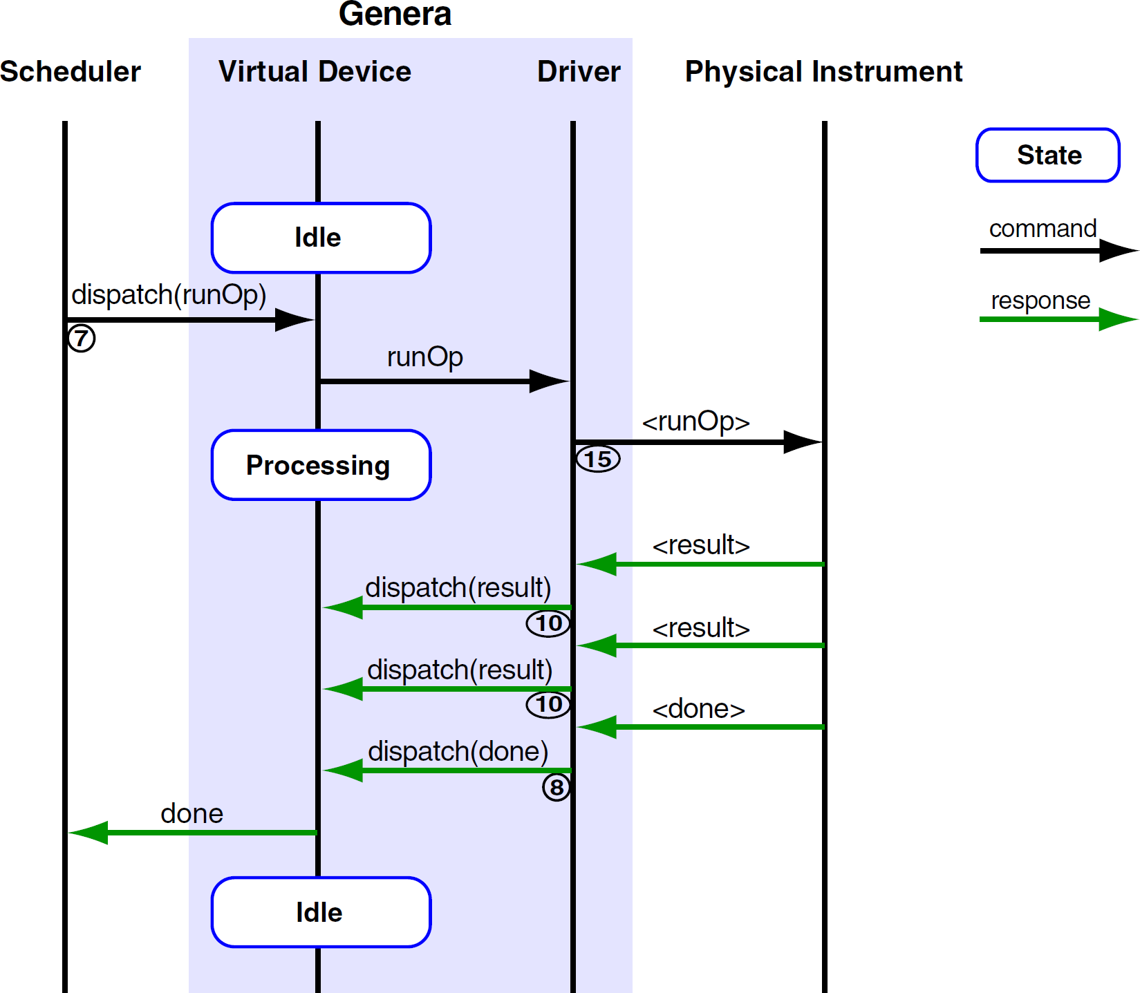
Successful command execution.
Validation of DSL Programs
DSL programs can be tested in two different modes without using the physical automated system. The estimation mode allows the system integrator to estimate the schedule and examine its timing constraints. In some systems, the execution time of some activities (e.g., incubation sequence) might be constrained by a time window. In other words, if the incubation activity does not complete at the specific time instance, the assay will not be valid.
The execution mode can also be used to test DSL programs. When the execution mode is used for testing, the Genera drivers should run in an offline mode. When the stub mode is used, the Genera driver does not communicate with the physical instrument. The Supra scheduler, however, executes, as it would execute in the production environment.
Virtual Simulation
With an additional 3-D simulation tool (SimView), we can also test the automated system for collisions and for errors that might occur because of the erroneously written DSL programs. For example, a gripper could be mistakenly opened while a robotic arm carries a microplate. This error could not be caught by the previous two stages of validation; however, it could be easily detected by our 3-D simulation tool.
Conclusion
In this article, we gave an overview of our Java suite of products, which are used to integrate instruments and data in laboratories. The products included an integration framework (Genera), a hybrid scheduler (Supra), and a Webenabled data tracking and visualization tool (DataPilot). We explained each of these applications in detail and showed how they can be used in the ELISA system.
One of the strengths of our tools is a formal method of system integration. The system integrator must define the instrument properties along with its available commands in XML before the instrument driver can be loaded into the Genera framework. If the XML file is not created properly, the framework will not load the corresponding instrument driver. Also, each instrument driver has a well-defined instrument interface. For the detailed description of instrument interfaces, please refer to the Genera Integration Guide. 1
Because of the limited scheduling features within current integration frameworks, we developed a hybrid scheduler. Our DSL scheduling language provides a flexible and powerful way of controlling and scheduling automated system activities in which the user has a choice of selecting the appropriate scheduling algorithm.
We also presented the benefits and drawbacks of each scheduling approach hoping to clarify widely spread misconceptions about them. We hope that this article will benefit system integrators and end users who are looking for different integration and scheduling tools for their automated systems.