
Abstract
We propose an automatic scanning microscope that is capable of analyzing the properties of the biofilm-associated cells by using optical and impedance spectroscopy. The operating principle of the instrument is based on measuring the electrical impedance of cell culture grown on a conductive substratum that is used as one of the electrodes. At low frequencies, the impedance analysis is capable of characterizing a biofilm at the macroscale, and at high frequencies it is capable of analyzing the peculiarities of a cell layer at the level of single microorganisms. The combination of these two techniques is sufficient to give a quantitative and structural composition of a biofilm at both levels. The developed instrument can be useful in the broad range of biofilmrelated research studies, providing the data for detailed, real-time, computer-controlled, noninvasive analysis of cell-to-cell and cell-to-surface interactions.
Keywords
Introduction
Dielectric spectroscopy is a noninvasive technique that can be used to characterize the structure and electrical properties of heterogeneous systems, especially artificial and biological membrane systems and suspensions of biocolloidal particles (biological cells). The permittivity and conductivity (dielectric dispersion) of biological heterogeneous systems depend on oscillating voltage frequency in the radio-frequency range. Changes of these properties are caused by the interfacial polarization or the Maxwell-Wagner effect, 1 which is due to the charge buildup on the interfaces between different materials. The intensity and the characteristic frequency of dielectric dispersion are strongly related to the structure and electrical properties of the tested system. By using an appropriate probe frequency, it is possible to distinguish between different structures in heterogeneous systems.
The characterization of individual cells and cell groups by dielectric spectroscopy has many advantages over traditional techniques of studying cell populations, such as optical microscopy. One instrument that uses such a method is known as a scanning capacitance microscope. On the basis of local electric interactions between a probe electrode and a sample, the scanning capacitance microscope provides the topographic and capacitive images of nonconducting structures at an ultra-high frequency. 2 Another instrument that uses the same principle as the scanning capacitance microscope is the scanning ion-conductance microscope, 3 which offers the topographic and ion current images of nonconducting surfaces covered with electrolytes. However, these instruments lack the ability to obtain the local complex resistance values of samples in aqueous media over a wide frequency range, which a scanning impedance microscope can provide.
A multiscale analysis of biological systems from a single cell level to the whole population is a recent trend in the biological and medical research. Phenomena studied so far include the following: cell sedimentation, 2 cell aggregation, 4 cell division and growth in culture, 3 organ deterioration, 5 and embryogenesis of single frog embryos. 6 The advent of the instruments capable of performing rapid and automated measurements in a wide range of frequencies has made it possible to study the dielectric behavior of cells in time-dependent phenomena. However, there are no specific instruments available for the investigation of cell-to-cell and cell-to-surface interactions using dielectric spectroscopy. There are two types of instruments that are currently being used in this area of research: scanning electrochemical microscopes 7,8 and stationary microelectrode-type assays. 9 These instruments have two major weaknesses: (1) they cannot thoroughly perform a multiscale analysis of the system from a subcellular to a whole population level (i.e., in a range of 10−6 to 10−3 m) and (2) they do not allow combination of research techniques based on different physical principles, which might be necessary to study complex biological systems. Our new instrument allows combination of several research methods in one experimental procedure and therefore can be used effectively in the investigation of cell-to-cell and cell-to-surface interactions.
System Integration and Instrument Design
We have developed a scanning impedance microscope designed without mechanical interactions between the probe (scanning electrode) and the sample. This in effect will reduce the agitation of the sample that may be caused by conventional scanning probe microscopes with direct contact between the probe and scanned surface. In addition, combining impedance spectroscopy with the spectrophotometric measurements will result in exhaustive information about the studied system.
Hardware Design
It is possible to measure the electrical characteristics of the system by applying a small (to avoid polarization) potential difference between the two electrodes. If the surface of one of the electrodes were used as a substrate for cell assays (adhesion, proliferation tests, and so on), it would be possible to nondestructively measure the local complex resistance or impedance of the cellular layer with high spatial resolution. There are several advantages to the proposed approach, including the possibility of obtaining high-resolution images without mechanical stress to the cells; the absence of shear stress forces induced by the moving probe; and the capability of real-time observation of the sample during the scan. The measurement unit of the developed scanning impedance microscope is depicted in Fig. 1. The instrument can be considered as a complex hierarchical system consisting of three levels. The first level corresponds to a measuring chamber, the second level contains the scanning stage and the microscope assembly, and the third level is the level of the whole system integration, which combines the hardware, image analysis, and data processing (Fig. 2).

The measurement unit of the instrument: electrochemical (measuring) chamber assembly (I) and combined optical-electrochemical scanning probe (II). Two possible designs of the scanning head: separated (IIa) and integrated (IIb) optical/electrochemical probes.
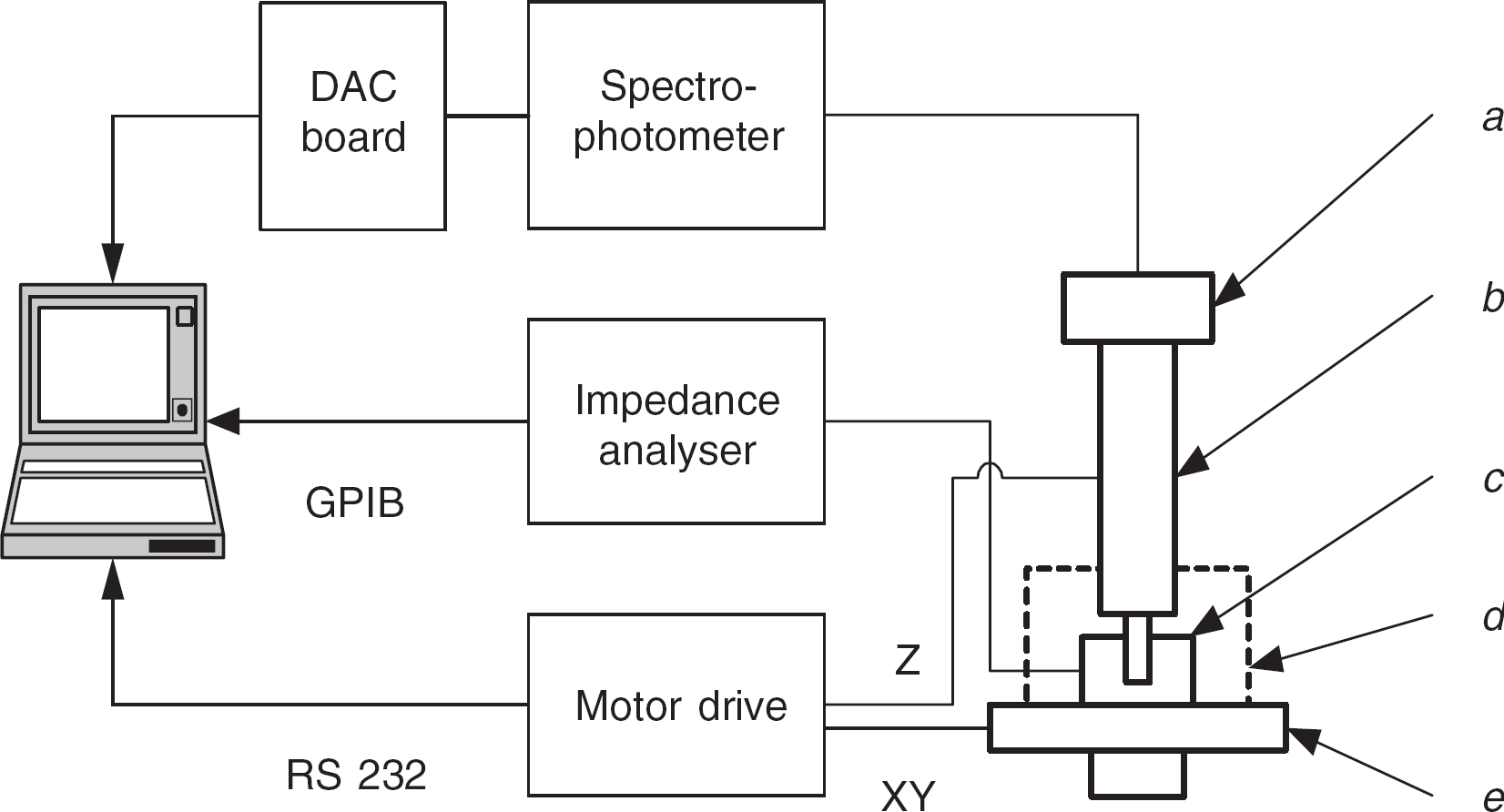
A block diagram of the scanning impedance microscope.
The measurement unit of the proposed instrument consists of four main parts. The electrochemical chamber (I) is made of polystyrene; its volume is 2 cm3. The instrument design allows use of a standard 24-well micro-plate, increasing universality and throughput ability of the instrument. The front (upper) side of the conductive sample (Fig. 1d) is in direct contact with the medium. The surface exposed to the electrolyte has a circular shape, and its area is ∼2 cm2. Scanning motion is performed by a high-resolution scanning stage (Fig. 1e), whereas the electrochemical chamber has no moving parts.
The key element of the measuring chamber is the conductive substrate that is used for cell attachment and growth (Fig. 1d). A conductive thin film, a double-sided carbon tape, serves as a bridge between the electrode and the source of input signal. The counter electrode (Fig. 1a) is made of 10-μm gold wire, insulated with an epoxy resin and immersed into the medium (Fig. 1b). The lateral resolution of the instrument is a function of the effective probe area, accuracy of probe positioning, and sensitivity of the impedance analyzer. The cells (Fig. 1c) can be cultured on the substratum surface before scanning or may be directly inoculated into the electrochemical chamber. The existing structure of cultured cells is characterized by the complex impedance 3-D (x, y, frequency) map. In case of a dynamic cell addition to the chamber, the corresponding impedance map becomes 4-D (x, y, frequency, t). Time resolution of dynamic measurements is limited only by the sampling rate of the data acquisition system and by the speed of the scanning stage.
The frame and optics of a conventional upright microscope (Nikon Optiphot) have been used to build the new instrument. The scanning stage is attached to the microscope frame, and the electrochemical chamber is mounted on the scanning stage by special holders. The device currently uses probes that are separated from each other (Fig. 1IIa), so the areas that are scanned by the optical and electrochemical probes at the same instant are different. The optical part of currently used integrated scanning head consists of a tight bundle of seven optical fibers in an epoxy ferrule: six illumination fibers around one reading 100-μm fiber. To optimize the mapping process, we developed an integrated scanning head (Fig. 1IIb) that combines the optical and electrochemical probes, thus enabling a single representative scan for both optical and electrochemical probes to be performed simultaneously at the same location. The key element of the new scanning head is a receiving optical fiber coated with a conductive material that serves as an electrochemical and optical probe simultaneously.
Integration of all these parts requires proper matching of the dynamic characteristics of measuring and execution units. Commercially available instruments (HP 4192A Impedance Analyzer, OceanOptics S2000 spectrophotometer, and Prior Optiscan motorized stage, Cambridge, UK) were used to build the apparatus, which is schematically depicted in Fig. 2. In addition, a highly conductive metal box known as a Faraday cage (Fig. 2d) is mounted over the scanning stage to increase signal-to-noise ratio of the performed measurements by eliminating the interference of external electromagnetic fields.
Software Design
The measuring process is fully automated and controlled by the data acquisition and experiment control programs.
The control programs were developed using Labview (G-Language) with imbedded Matlab modules. The program defines how the impedance analyzer and the motorized stage work together to measure impedance values over the surface of a 1280 × 1280-μm grid. The program alternates so that the stage moves in a raster scanning motion in 10-μm increments. Each movement is followed by the impedance analyzer scan, which determines the impedance and phase angle shift at each point. The program initializes by creating an ASCII-text file that is named, placed, and saved by the user who stores the evaluated data. In addition to the saved text file, the user also defines the following parameters for the Impedance Analyzer: measured function (impedance or phase angle), type of signal triggering, circuit mode, testing frequency, scanning frequency, and oscillating voltage. User-defined parameters for the Optiscan motorized stage include origin position, X and Y step sizes, the number of iterations for X and Y steps, and the number of times to repeat the raster scan loop.
After creating the text file and defining the variables that it will use, the program opens a loop, which encloses all parts of the program sequenced to move the motorized stage and to perform surface scanning with the impedance analyzer in a two-step process. The first step of the loop directs the Optiscan motorized stage to move forward in the X direction, and the second step tells the impedance analyzer to scan the surface. In the first sequence, the Optiscanmotorized stage is operated via the RS232 serial port, and therefore the serial port is called (ASRL1::INSTR) using a LabView command block. Once the serial port has been called, it is then configured to function with the Optiscan motorized stage at the following settings: 9600 baud rate, 8 data bits, no parity, “1” stop bit, and no flow control. Subsequently, the program opens the serial communication port via the VISA architecture Open command. Here, a string is concocted using the build string block to move the motorized stage for the specified distance. The value of the appropriate step size and control commands are concocted together to build a string that is finally sent to the Write VISA command block, which is given a preset delay time so that the Optiscan stage has time to read the command after it completes its previous movement. Once the data have been read by the Optiscan stage, the VISA is Cleared and Closed by the respective command blocks. Within this sequence, the program calculates the position of the motorized stage and sends the position data to the user-created text file.
The second program sequence consists of several steps that instruct the HP 4192A Impedance Analyzer to scan the surface of the culture. The impedance analyzer GPIB port is called, and all the parameters defined by the user are applied to define values for the mode selector at the first step. Measurement mode parameters are formatted and then sent to the GPIB Write command block. In the next step, the protocol waits for service from the analyzer to allow for data to be sent back to the computer. When a service request is sent to the GPIB controller, the program reads measured values via the GPIB Read command block and then sends the values to the user-created ASCII file. The analysis of the optical spectrum data is performed in the same manner from a specialized DAC acquisition board.
Once all the data have been collected, they are translated into scientific notation and sent to the user-created text file. The data are then filtered through a 2-D noise reduction procedure, analyzed, and plotted on a 3-D surface and contour plots by Matlab 6.5 (MathWorks, Inc., Natick, MA).
Application of the Developed Instrument for Biofilm Studies
A biological cell is a heterogeneous system that consists of a plasma membrane and a cytoplasm. The plasma membrane comprised of a lipid bilayer with embedded proteins has low ionic permeability and therefore can be regarded as a low conducting thin shell. If the cytoplasm is assumed to be homogeneous, the simplest electrical model of the cell is a conducting sphere covered with an insulating thin shell. 10 This model explains the dielectric relaxation of cell suspensions due to interfacial polarization, or the Maxwell-Wagner effect.
Escherichia coli O157:H7 is a virulent pathogen that is known for its catheter-associated urinary tract infection. It is the most common nosocomial infection contributing to patients' morbidity and mortality, and it is the major cause of infections acquired in hospitals and other healthcare facilities. 11 Many studies have found that Escherichia coli can adhere to surfaces. 12,13 Attachment and subsequent detachment are characteristic of Escherichia coli interactions with surfaces. 14 Like many bacteria, Escherichia coli attached to a surface can form biofilms, exopolysaccharide-encased communities of bacteria that resist biocides and other sanitizers. 15 Adhered cells and biofilms are a constant concern in medicine and processing environments. The developed scanning impedance microscope can be used for investigating survival strategies of microbial pathogens with the ultimate goal of devising strategies for controlling bacterial spoilage and preventing inflammatory diseases.
Test Sample Preparation and Biofilm Growth
E. coli strain O157:H7 was obtained from the pathogens collection at the Department of Food Science, Rutgers University. It was cultured in a tube by aseptically transferring 20 μL from a stock refrigerated E. coli to 10 mL of bovine brain-heart infusion broth (BHI, VWR International) and then incubating at 37 °C for 24 hours.
Aluminum has been chosen as the abiotic substrate material for biofilm growth because of a broad range of biomedical applications. Aluminum alloy has a well-developed surface with a variety of surface patterns (grooves, hills, and so on); hence, it can be used as a model substrate for studying biofilm formation on engineered real-life metal surfaces. Aluminum coupons (12.8 mm in diameter) were cut out of a cold-rolled commercial grade aluminum alloy 1100 (McMaster, Inc.). After the coupons were cut, they were transferred to beakers with 20 mL of acetone added to each and then were sonicated in a FS30 sonicator for 10 minutes. The cleaned coupons were transferred to dry Petri dishes (Pyrex, VWR International, Bristol, CT) and were kept in an oven at 150 °C for 3 hours. Afterwards, the aluminum coupons were installed into the measurement chamber and connected with the measurement circuit. The chamber was then filled with the bacterial culture; after 24 hours, the culture was removed and replaced with fresh BHI medium. The system was then ready for scans.
Instrument Calibration
Optical and electrochemical spectrometry are very powerful methods that can deliver the most complex information about the studied microbial community. However, to interpret the obtained data and to choose the best regimes of operation, preliminary knowledge about the studied system and calibration measurements are necessary. For example, the wavelengths responsive to the changes in the microbial culture were determined from the following experiment.
An established E. coli culture was divided into two equal parts. One part was processed by centrifuge, and the obtained supernatant solution was filtered to remove all cells. This solution was used as a background medium to extract the cell-related part of an optical signal from the measurements of the E. coli culture. The supernatant and the whole bacterial culture were placed into standard optical cuvettes, and their respective adsorption spectra (200–850 nm) were measured. The difference between these spectra is depicted in Fig. 3. It determines an optimal wavelength for bacterial cell detection, which was found to be 570 nm.
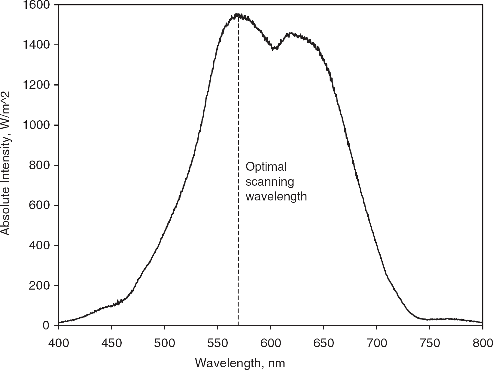
The difference between the adsorption spectra of supernatant solution and bacterial culture, which determines an optimal wavelength for biofilms spectrophotometric scanning.
The optimization of the impedance measurements was performed in two sets of experiments. First, impedance spectra of bacterial cultures with various cell concentrations were measured in a two-electrode conductivity chamber. Our observations indicate that only the high-frequency part of the impedance spectrum responds to the change of cell concentration and that the low-frequency part of the spectrum does not change in a broad range of cell concentrations.
The complex resistance of a biofilm is a function of its surface coverage and organization (structure). Changes in the cells' organization and their physiological patterns can be characterized by impedance spectra. The second set of experiments was performed to evaluate the possibility of using impedance spectroscopy for in situ monitoring of the biofilm formation process. For this purpose, biofilm formation and growth were continuously monitored by using a two-electrode scheme during a 4-day-long experiment. The resulting changes of the impedance spectra are depicted in Fig. 4. Measured impedimetric signal reflects changes of the biofilm's complex resistance and permittivity, which correspond to changes in the cell concentration. As one can see from the plot, the formation of biofilm impacts both high-and low-frequency regions of the spectrum. The impedance response at low frequencies can be used to evaluate biofilm structure, whereas the impedimetric measurements at high frequencies reflect single cell-related phenomena.

The phase angle of Escherichia coli biofilm changing with time of growth: 1 day (♦), 2 days (δ), and 4 days
Two specific frequencies for monitoring cell suspensions were determined by the analysis of the time-lapse impedance spectra to be 10 MHz and 12 Hz. At 10 MHz, it is possible to monitor single-cell activity, and at 12 Hz it is possible to monitor biofilm-related activity.
Biofilm Analysis with a Scanning Spectrophotometric Impedance Microscope
An E. coli biofilm cultured for 24 hours was studied with the developed scanning electrochemical-spectrophotometric microscope. To increase the accuracy of the measurements, optical and impedimetric scans were performed independently over the same field. Fluorescent and phase-contrast optical microscopy were used as control techniques to monitor cell adhesion and biofilm development.
A fluorescent microscopy image of studied biofilm (Fig. 5) shows that the biofilm uniformly covers the entire metal substrate. The biofilm is well developed, and separate colonies cannot be distinguished.

Fluorescent image of E. coli biofilm on the aluminum surface (1400 × 1200 μm).
Fig. 6 shows electrochemical impedance maps of the studied biofilm. They both reflect an internal structure of the matured biofilm with no distinct colonies or empty spaces. There is no significant difference between the impedance and phase angle maps. As expected, impedimetric scans support the results of a fluorescent analysis that the matured biofilm has uniform structure. As we know, these low-frequency scans reflect structural peculiarities of the whole biofilm, including cells and the exopolysaccharide matrix.

Electrochemical mapping of E. coli biofilm on an aluminum surface at 12-Hz scanning frequency: (A) impedance map, (B) phase angle map.
To investigate the distribution of individual cells in a biofilm, the second scan at a high oscillating voltage (10 MHz) was performed. Impedimetric maps in Fig. 7 show that at the center of the studied zone, cells are distributed uniformly, which is normal for the matured biofilm. However, a region with higher cell population density is observed to the left of the impedance map (see Fig. 7A). In fact, this region corresponds to a surface pattern (groove) in which the cell population is denser because of growing conditions in the confine. Noticeably, these peculiarities are reflected in the impedance map only, and the phase angle map does not provide any information regarding cell population density distribution within the biofilm. In general, phase angle maps at 10 MHz and 12 Hz are very similar and characterize the diffusion resistance (i.e., the density of the exopolysaccharide matrix) within the biofilm.

Electrochemical mapping of E. coli biofilm on an aluminum surface at 10-MHz scanning frequency: (A) impedance map, (B) phase angle map.
Optical (reflectance probe) scanning of the biofilm produces a surface map (see Fig. 8) similar to the high-frequency impedance image (Fig. 7A). Surface patterns and associated changes in cell density can be seen as dark and light zones. However, actual resolution of the optical scan is lower than that of the dielectric image because of the greater probe size.

Optical scanning (570 nm) biofilm image.
Conclusion
We propose an automatic scanning microscope that is capable of analyzing the properties of the biofilm-associated cells by using optical and impedance spectroscopy. The operating principle of the instrument is based on measuring the electrical impedance of cell culture grown on a conductive substratum that is used as one of the electrodes. At low frequencies, the impedance analysis is capable of characterizing a biofilm at the macroscale, and at high frequencies, it is capable of analyzing the peculiarities of a cell layer at the level of single microorganisms. The combination of these two techniques is sufficient to give a quantitative and structural composition of a biofilm at both levels.
The developed instrument can be useful in the broad range of biofilm-related research studies, providing the data for detailed, real-time, computer-controlled, noninvasive analysis of cell-to-cell and cell-to-surface interactions. Further integration of the combined microelectrode-fiber optics scanning head with standard fluorescent microscope optics would allow the building of a new measuring system with extended research capabilities.