
Abstract
We have recently begun to explore the use of UV laser ablation micromachining to construct microfluidic devices in polymers. This technique can create microchannels rapidly and modify the resulting polymer surface in a single step. By ablating under different atmospheres, it is possible to alter both the surface chemistries and physical surface morphologies of the microchannels. We have employed electroosmotic flow measurements, chemical mapping, and optical microscopy to characterize the microfluidic devices. In addition, we have studied the parameters affecting the ablation, such as the laser wavelength, laser fluence, laser firing repetition rate, and the material being ablated.
Keywords
INTRODUCTION
The first miniaturized, planar analytical system was reported in 1979 and consisted of a gas chromatograph fabricated on a silicon wafer using integrated circuit technology. 1 In 1992, Manz et al., reported the first capillary electrophoresis on a planar device and detailed the separation of calcein and fluorescein on a fabricated glass chip. 2 Since that time, there has been increased interest and activity in the miniaturization of analytical systems. Recently, researchers in the Human Genome Project have used miniature, planar capillary electrophoresis devices to separate and analyze DNA fragments. Various methods have been utilized to fabricate such devices, including photo and x-ray lithography, chemical etching, hot wire imprinting, silicon template imprinting, and casting with poly (dimethyl siloxane). 3 –12
Traditionally, microfluidic devices have been fabricated in silica or glass because of their well-understood physical and chemical properties. This substrate is advantageous because of
a well-established surface chemistry,
easy transfer of existing technologies (such as capillary electrophoresis and DNA hybridization protocols) to miniaturized systems,
can be fabricated using techniques developed for silicon,
has general chemical inertness, and
has very low electrical conductivity. 9
However, using silica or glass as a substrate material has some disadvantages such as low limiting aspect ratios obtained through chemical etching, its time consuming fabrication process, and its fragility resulting from its inherent brittleness. Recently, polymer substrates have been proposed as alternatives. Polymers offer advantages over silica including facile micromachining, a wide availability of polymer chemistries that may be tailored to specific chemical and physical needs, and the possibility for low cost of device production. Some of the inherent disadvantages include variations in the chemical and surface properties from lot to lot and the lack of well understood surface chemistries. Researchers have utilized LIGA (German acronym for lithography, electroplating, and molding) 13 –15 imprinting and embossing, 8 ; 10 ; 11 ; 16 ; 17 injection molding, 18 ; 19 and laser ablation 20 –22 to construct microfluidic devices in various polymer substrates.
UV laser ablation of polymers occurs when a polymer is exposed to laser emission at a wavelength where it strongly absorbs photons. The ablation occurs when chemical bonds are broken and a subsequent pressure ejection of material at supersonic speeds follows. Srinivasan first reported this effect when he described the laser ablation of PET in 1982. 23 It is important to note that laser ablation is a chemical effect with lack of detectable thermal damage to the surrounding substrate. This is important when one considers utilizing laser ablation to machine polymers.
With laser ablation micromachining, polymeric devices are fabricated by focusing the output of a laser onto the surface of the polymer. Either moving the surface relative to a fixed laser beam with a two-dimensional stage or moving the focused beam relative to a fixed substrate creates the pattern. Using this “direct-write” technique, we have etched simple lines and spirals with micrometer-sized geometry on a variety of different commercial plastics. In our laboratory, direct-writing is accomplished with a computer-controlled two dimensional x-y stage that utilizes CNC (computer numerical control) commands, similar to those used in automated metal or woodworking. We utilize a laser micromachining system (LMT-4000 Laser Micromachining System) purchased from Potomac Photonics, Inc. (Lanham, MD) equipped with a KrF pulsed (7 ns) excimer (248 nm) laser and an Aerotech Unidex 500 PC-based motion controller (Pittsburgh, PA). It is possible to control the repetition rate of the laser firing from a single shot to 200 Hz, and the motorized stage has a ± 1-micrometer repeatability. The micromachining system is also equipped with real-time video for visualization, positioning, and dimensioning during the device fabrication. The system, shown in Figure 1, makes it possible to vary the local environment around the ablation site. By equipping the micromachining system with a gas-fed nozzle, the ablation site can be swept with a gas. The pressure of the gas feeding the nozzle is controlled with a gas regulator. Ablating through 248 nm transparent liquids on the substrate surface provides another means to control the local chemical environment around the ablation site.
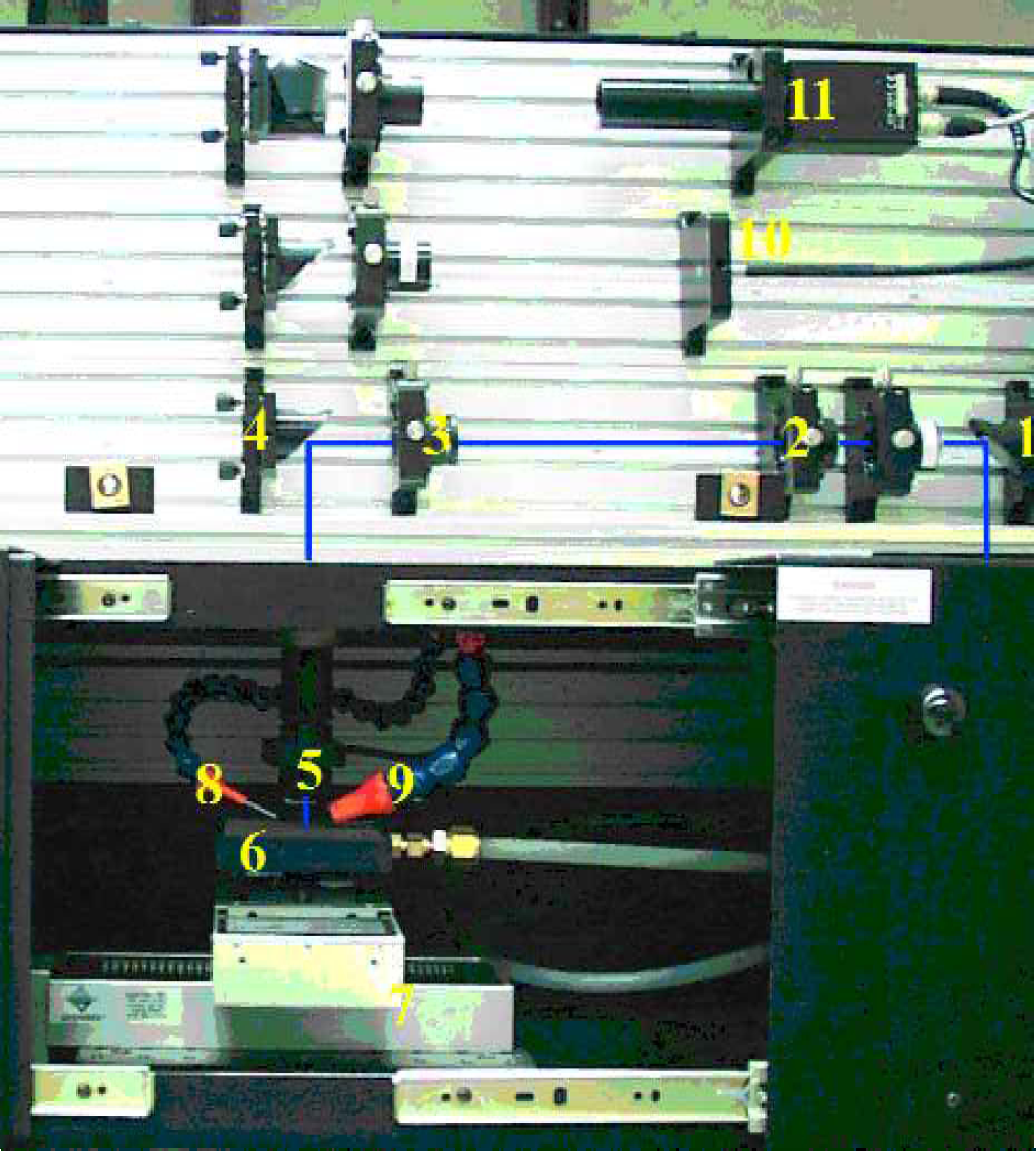
The laser ablation micromachining system. The black line denotes the path of laser emission. The beam is deflected by turning mirror (1) onto aperture (2), passes through iris (3), and is steered by dichroic (4) through the focusing objective (5). The vacuum chuck (6) is mounted on a computer controlled x-y stage (7). The surface of the substrate may be exposed to various gases via nozzle (8) and the vacuum port (9) assists in removal of large debris. The entire process is illuminated with a light source (10) and imaged with a camera (11).
The CNC language used to control the mechanical stage is similar to Beginner's All-purpose Symbolic Instruction Code (BASIC) and allows the programmer to use loops and prompt the user for variables. Code to form common geometric patterns, such as semicircles, is predefined. Coordinates are either programmed in an absolute mode, with each movement made with respect to a user-defined origin, or a relative mode, where each subsequent movement is made with respect to the current position of the stage. By utilizing format conversion software, it is possible to fabricate devices directly on the micromachining system from designs created with computer drawing applications, such as CorelDraw. Saving CorelDraw files in DXF (Data eXchange File) format allows them to be converted to CNC files with the aid of a conversion utility called Gcode2000 (Andrew R. Clayton, Salisbury, NC, http://members.aol.com/gcode2000/). This method speeds up the design process and allows complex geometric patterns to be created rapidly.
Laser ablation of polymers is commonly accomplished using UV light. Excimer lasers at wavelengths such as 308 nm (XeCl), 248 nm (KrF), and 193 nm (ArF) and quadrupled and tripled Nd:YAG lasers (266 nm and 355 nm) have been utilized to ablate polymer substrates. Laser micromachining at longer wavelengths such as using doubled Nd:YAG lasers in the visible (532 nm), Ti: Sapphire and Nd:YAG lasers (1064 nm) in the near infrared, and even CO2 lasers in the infrared have been reported in the literature. 24 –27 Typically, the lasers utilized to fabricate microfluidic systems provide both high peak powers and variable repetition rates, parameters that prove to be important in the fabrication process. It is important to note that as the wavelength of the ablation laser decreases in the UV, the energy necessary to ablate the polymer also decreases. This is a direct result of the increased electronic absorption cross-section of polymers at shorter wavelengths that improves the efficiency of light absorption.
The physical morphology of the microfluidic channels is determined by a number of parameters including the laser fluence, the spot size of the focused laser output, the translation speed of the x-y stage, the repetition rate of the laser firing, the nature of the substrate being ablated, and the local chemical environment under which ablation occurs. The laser fluence is typically expressed as the energy per unit area (mJ/cm2). At very low fluences, the laser has no visible effect on the polymer substrate; however, as the fluence is increased there is a point at which there is sufficient power density to break chemical bonds and remove material from the substrate. This is known as the ablation threshold. 28 We have determined that the higher one increases the laser fluence above the ablation threshold for a particular polymer, the deeper is the resulting channel that is ablated; however, the surface of the resulting channel and area immediately surrounding the channel become more jagged and rougher. Conversely, a lower laser fluence produces a shallower, but smoother channel. Using a laser fluence that is too low results in a lack of any observable ablation, laser-induced periodic structures, and/or alterations in surface charge without a physical loss of material. 29 –31
The nature of the substrate material plays a very important role in the morphology of laser-ablated channels. So far, we have examined poly (methyl methacrylate) (PMMA), poly (vinyl chloride) (PVC), poly (ethylene terephthalate glycol) (PETG), and polycarbonate (PC) and have noted differences among the ablated features that appear to be material dependent. For example, ablated structures in PMMA have a rougher surface and exhibit more cracking as compared with those in PETG, PC, and PVC. These differences are thought to be a result of the light absorption properties of the material at the ablation wavelength, which dictate whether thermal or chemical changes dominate the ablation process. But they may also be due in part to other physical differences such as the thermal conductivities of the polymers.
The geometric spot size of the focused laser beam is defined by the demagnification of the focusing objective and the size and shape of the masking aperture utilized. The aperture mask defines what is to be imaged and focused onto the substrate. The aperture is typically a circle or a square that has dimensions ranging from tens of micrometers to a few millimeters. After passing through the aperture, the light is focused through a lens onto the substrate surface. The energy received per unit time determines the depth of ablation and is defined by the rate of the x-y stage movement, the repetition rate of the laser firing, and the laser fluence. A slow rate of x-y stage movement and a high laser firing repetition rate translate to a higher number of pulses and an increased depth for a defined area. However, the depth of focus of the laser spot limits the depth of a channel (or feature), because as the laser spot moves out of focus, the fluence decreases. This problem may be circumvented when etching deeper structures, if the focus is readjusted for subsequent passes.
The laser firing repetition rate and the velocity of the x-y stage also determine the gross roughness of the microfluidic channel. Figure 2 shows channels fabricated using a constant laser firing rate and stage velocities of 10 mm/s, 2.5 mm/s, and 0.625 mm/s. Smoother channels are obtained by using slower velocities, lower laser fluence, and higher firing repetition rates. Other researchers have reported the root-mean-square roughness values of polycarbonate before and after laser ablation as approximately 0.8 nm and 4.8 nm, respectively. 32
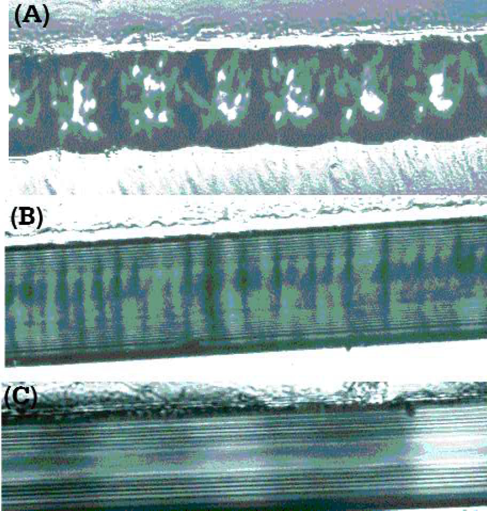
Micrographs of a microchannel fabricated in PETG at various x-y stage velocities. Ablation occurred at 248 nm with a laser fluence of 555 mJ/cm2. The micrographs are at 20 times magnification. The stage velocities were (A) 10 mm/s, (B) 2.5 mm/s, and (C) 0.625 mm/s.
The physical morphology of the channels is also a function of the local atmosphere under which ablation occurs. Figure 3 illustrates the different cross sections obtained in PMMA after ablation under nitrogen, methanol, and water. Ablation under nitrogen and methanol resulted in rectangular channel profiles, whereas ablation under water resulted in a wedge-shaped profile. This difference in cross section has been discussed in previous work 33 and is thought to be the result of self-focusing or re-focusing of the laser beam as it passes through water. In addition to the self-focusing effect, the water assists in the liberation of debris that is usually left behind in the laser ablation process as evidenced by the lack of particulate in the channel of Figure 3C. Ablation of PMMA under methanol (Figure 3B) resulted in cracking of the material probably caused by methanol migrating into crevices and exploding when exposed to the laser. Thus, by controlling the local atmosphere under which the ablation takes place, we can substantially alter the surface area of the channel walls.
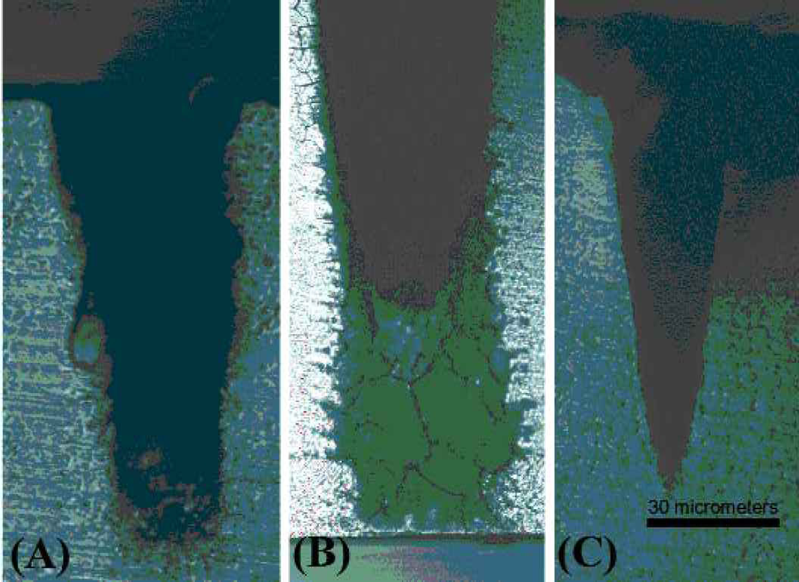
Illustration of the different aspect ratios obtained in PMMA after ablation under (A) nitrogen, (B) methanol, and (C) water at 248 nm with a laser fluence of 555 mJ/cm2.
It has been determined that the physical morphology of the ablated region is dependent upon the temporal profile, the spatial profile, and the wavelength of the laser pulse. The longer the laser pulse length, the greater the fluence required to ablate the substrate. This is because the ablation of the surface of the polymer is a function of the energy deposited per unit time. 28 Ablation pulse lengths may range from hundreds of femtoseconds to tens of nanoseconds and are dependent upon the physical characteristics of the laser used. For a corresponding fluence of 300 mJ/cm2 the power density may range from 15 MW for a pulse length of 20 nanoseconds to a power density of 15 petaWatts for a pulse length of 20 femtoseconds. Similarly, for a given substrate material, different ablation wavelengths afford different limiting aspect ratios. A poor spatial profile of the laser beam results in poor feature quality and repeatability since it dictates the geometric shape of the ablated area.
In addition to physical changes in the ablated structures caused by differences in the atmosphere local to the ablation site, we have also observed changes in the surface chemistry and surface charge of ablated polymer substrates. Alterations in the charge on channel surfaces is important because the surface charge density is critical in determining and maintaining electroosmotic flow (EOF) in micro-channels. As Figure 4 shows, ablation of polycarbonate under different atmospheres results in channels with differing electroosmotic flows. (Flow measurements were performed by sealing the ablated channels with PDMS and using either the flow imaging 34 –36 or the current monitoring 37 ; 38 method.) The alterations in surface charge in ablated polymer microchannels are thought to be due to changes in the chemical functionality of the polymer surface. This can be demonstrated by using a fluorescent labeling technique to map charge densities chemically. For instance, the ablation of PETG (a polyester) may be reasonably expected to result in free carboxyl moieties due to cleavage of the ester bonds. Under the influence of a carbodiimide-linking agent, reagent amino-fluorescein reacts with carboxylic acid moieties to form amide links that bind the fluorescent reagent to the polymer surface. Subsequent examination of the channel under a fluorescent microscope both images and maps carboxylic acid groups present on the surface of the polymer after laser ablation. Greater fluorescence intensity equates to greater charge density on the surface. As shown in Figure 5, the concentration of carboxylic acid moieties present after ablation is dependent on the chemical atmosphere under which laser ablation occurs. It is tempting to equate the lack of free carboxylate groups in the channels ablated under methanol with the possibility that the methanol provides the means to “cap off” these charged species through the formation of methyl esters on the surface-a possibility that does not exist during ablation under air.
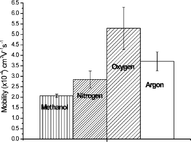
Bar graph showing different electroosmotic flows obtained in polycarbonate after ablation under different atmospheres. Measurements were performed after capping with a PDMS lid. All measurements, except for methanol, were obtained using a current monitoring method. Methanol measurements were obtained with the caged fluorescence method. Error bars represent the standard deviation from the mean (average of thirty measurements).
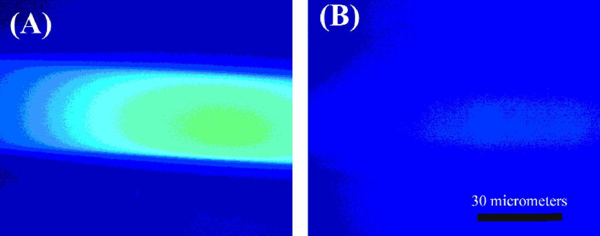
Fluorescence micrographs of channels in PETG substrates after ablation under (A) air (ambient atmosphere) and (B) methanol at 248 nm with a laser fluence of 555 mJ/cm2. As this figure illustrates, the concentration of carboxylic groups varies depending upon the chemical atmosphere under which laser ablation occurs.
Chemical modification of the microchannel surface is important in the fabrication of microfluidic systems because in many applications it is desirable to utilize wall charge effects to alter the magnitude of the electroosmotic flow. This is beneficial for controlling the movement of solutions in microchannel networks and optimizing separations. 39 Researchers have altered the electroosmotic flow by utilizing permanent or dynamic coatings. However, both of these techniques require additional fabrication and characterization time and raise issues about the stability of the surface during use. Laser ablation under different atmospheres permits modification of the surface chemistry during the fabrication process. However, we still need to investigate the stability of these surfaces over the course of multiple measurements.
Laser ablation micromachining provides a rapid way to fabricate polymer microchannel devices directly from computer-derived designs. By controlling the ablation parameters, one can create channels of strikingly different physical morphology. Furthermore, by controlling the chemical atmosphere local to the ablation site, one can alter the chemical characteristics of the resulting polymer surface that in turn can dramatically affect the electroosmotic flow characteristics of the device. By understanding and regimenting these important parameters during the fabrication of the device, it is possible to tailor its characteristics to particular needs.
ACKNOWLEDGEMENT AND DISCLAIMER
We would like to acknowledge partial support for this project from the NIST-National Research Council Post-Doctoral Fellowship Program. Certain commercial equipment, instruments, or materials are identified in this paper to foster understanding. Such identification does not imply recommendation or endorsement by the National Institute of Standards and Technology, nor does it imply that the materials or equipment are necessarily the best available for the purpose.