
Abstract
The design of a fully automated system for the analysis of DNA fragments in 96–well plates is described. Microfluidic technology is used to integrate sample loading, electrophoretic analysis, and fragment detection onto a miniature lab-on-a-chip device. The microfluidic chip operates in an instrument platform that automates sample access, data collection, and data reporting. Each microfluidic chip provides sizing and concentration values for more than 1000 DNA samples.
INTRODUCTION
Laboratories involved in DNA microarray research routinely generate thousands of DNA fragments per week using the polymerase chain reaction (PCR). Agarose slab gel electrophoresis typically is used to check the quality of these PCR products. Because slab gel protocols are difficult to automate, most laboratories employ traditional manual electrophoresis procedures, which require significant time and labor.
Microfluidic devices hold great promise for automating many types of laboratory experimentation, including electrophoresis. 1 –4 The first commercial instrument for microfluidic electrophoresis of nucleic acids and proteins, the Agilent 2100 Bioanalyzer, was introduced in 1999. This platform was co-developed by Agilent Technologies and Caliper Technologies and performs electrophoresis within microfluidic channels etched into glass wafers (termed “chips”). For DNA analysis, the channels are filled with a sieving polymer solution that contains a DNA intercalating dye. DNA fragments are detected after electrophoretic separation by laser-induced fluorescence (LIF). Each disposable DNA chip analyses 12 samples, which are manually pipetted into wells on the chip.
In this report we describe the development of the Caliper AMS 90, an automated microfluidic system for the analysis of DNA samples in 96-well microtiter plates. Our goal was to design a system that provides the same high data quality as the Agilent 2100 Bioanalyzer, but with increased automation and throughput. In the Caliper AMS 90, samples from 96-well plates are automatically introduced into a microfluidic electrophoresis chip using pressure-driven flow through a fused-silica capillary. No sample preparation is required for the analysis of crude PCR products or restriction digests. The system consumes only about 100 nL of each sample, and reliably processes 400–500 DNA samples in an 8-hour shift. Size (base pair) and concentration (ng/mL) values are calculated automatically for DNA fragments in the 100–5000 base pair size range.
MICROFLUIDIC CHIP DESIGN
We needed to accommodate two types of sample movement in the design of the DNA analysis chip; pressure-driven bulk sample flow for sample loading, and electric field-driven electrophoretic migration for separation. To minimize the interaction between these two modes, the channels used for electrophoresis were designed with very shallow depths to provide high resistance to flow. These shallow electrophoresis channels are filled with a viscous separation medium that further adds to the flow resistance (see below). In contrast, the sample-loading channel is etched much deeper than the electrophoresis channels. By using this dual depth design, the negative pressure used for sample loading produces almost no bulk flow in the electrophoresis channels. This isolation between the two sample movement modes permits simultaneous sample separation and sample loading, which decreases sample-to-sample cycle time.
Figure 1 shows the channel layout used in the DNA analysis chip. The channels are etched into fused-silica wafers and sealed by thermal bonding as previously described. 4 A 50 μm internal diameter fused-silica capillary is attached perpendicularly to the plane of the chip as shown in Figures 1 and 2. 5 To prepare the chip for analysis, wells 3, 5, 6, and 8 are filled with a proprietary polymer/dye solution that acts as the separation medium. The channels connected to these wells are flooded with the separation medium by applying positive pressure. Well 4 is filled with a solution that contains two DNA marker fragments; a small fragment (15 base pair), and a large fragment (7000 base pair). When the chip is inserted into the instrument, electrodes make electrical contact with the solutions in chip wells 3, 4, 5, 6, and 8. Well 1 interfaces with a pressure/vacuum seal. An x-y-z translation stage moves either a buffer reservoir, a DNA ladder reservoir, or the sample plate into contact with the tip of the capillary during operation. When negative pressure is applied to well 1, sample is drawn through the capillary onto the chip. The negative pressure also creates a flow of marker solution from well 4, which joins the sample flow at the capillary/channel joint (see Figure 1). The markers act as internal sizing and quantitation standards for the DNA assay. Typically, the entire sample channel from the capillary to well 1 is filled with the sample/marker mix. After the sample channel is filled, the negative pressure at well 1 is released and an electric field is applied between wells 3 and 6. Electrophoretic movement induced by the electric field drives DNA from a portion of the sample channel toward well 6, across the injection intersection. To produce an injection plug, the electric field between wells 3 and 6 is replaced by a field between wells 5 and 8. DNA at the injection intersection moves into the separation channel, where it is separated into discrete bands and detected by LIF. The next DNA sample is drawn onto the chip during the separation.
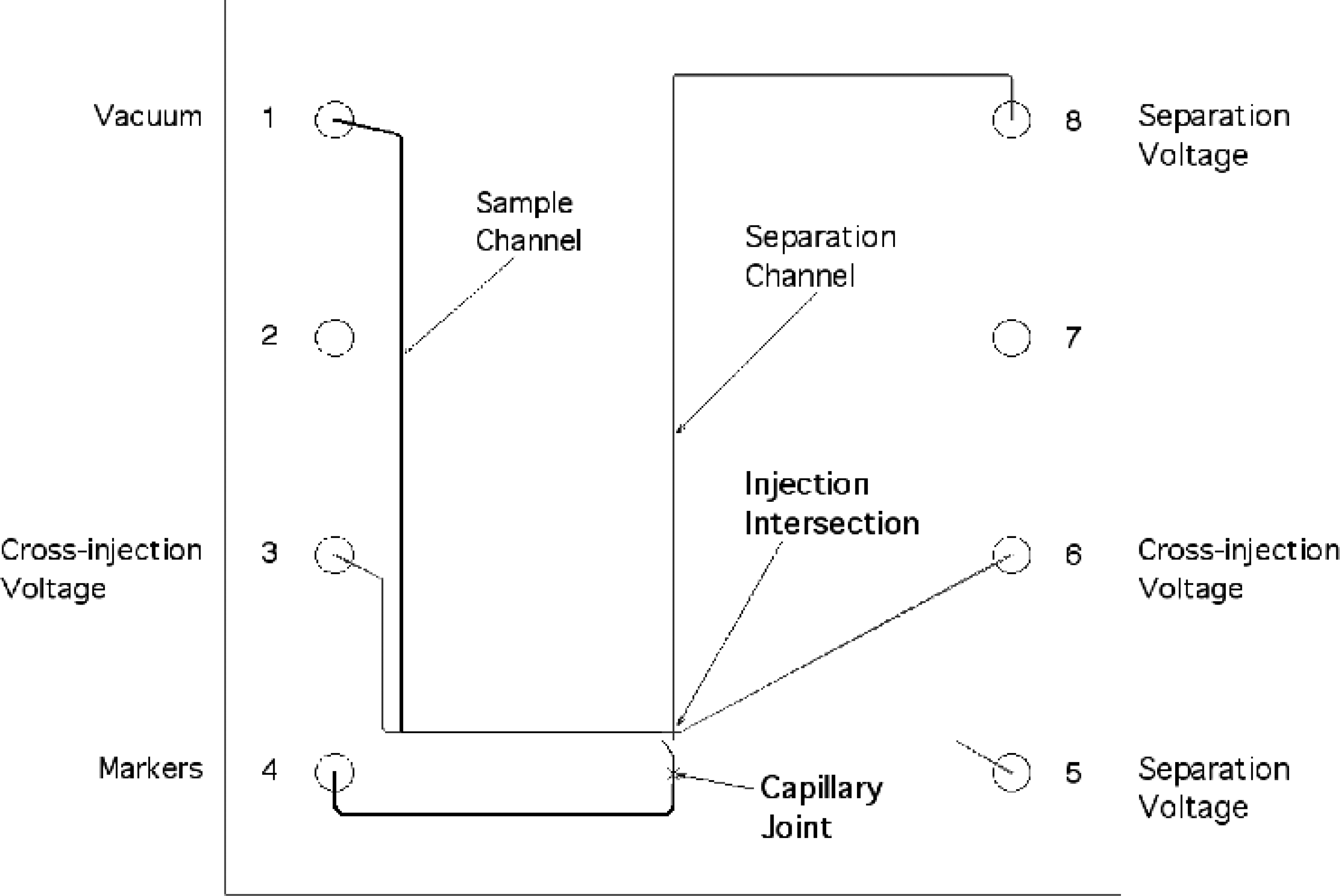
Layout of the DNA analysis chip. Electrodes make contact with wells 3, 4, 5, 6, and 8. The LIF detection point can be placed at any point along the Separation Channel.
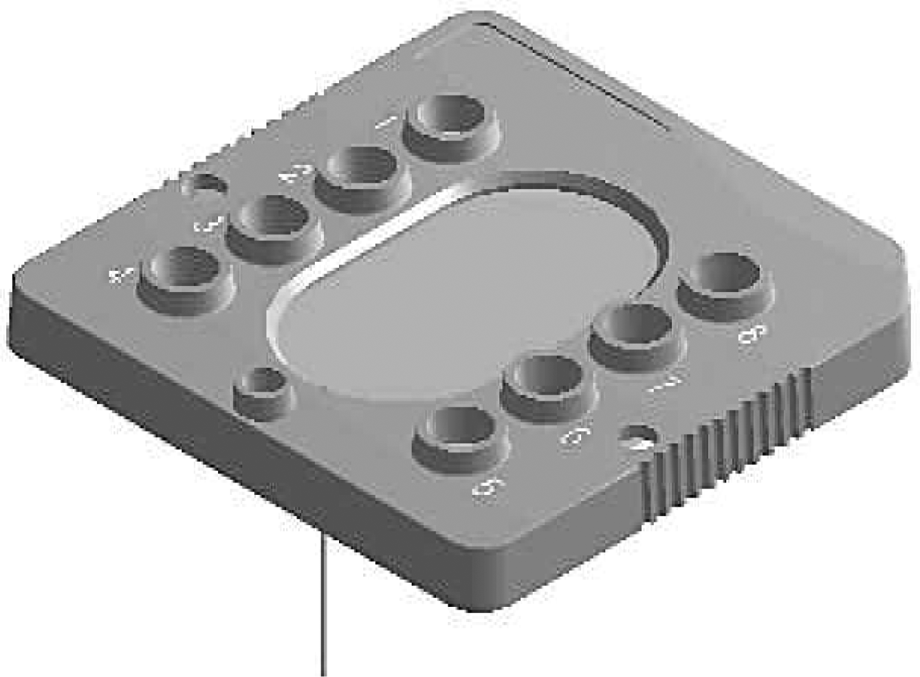
DNA analysis chip assembly. The chip is attached to a plastic caddy that forms the eight reagent wells. The sampling capillary extends approximately 2.5 cm below the plane of the chip.
We routinely analyze a reference DNA ladder before every 12-sample row of the 96-well plate. The ladder is located in a stripwell next to the 96-well sample plate, as is a wash buffer for cleaning the capillary tip between samples. The sizes and concentrations of DNA fragments in samples are calculated by referencing their migration times and intensities to known fragments in the DNA ladder. The on-chip addition of the marker solution to each sample provides improved analytical accuracy. Once an analytical run is initiated, all samples in the 96-well plate are analyzed in an automated fashion.
AUTOMATION DESIGN
To automate sample access, the sample plate is mounted on an x-y-z translation stage. The DNA analysis chip is inserted into a fixed chip mount assembly that contains the system's optical components, auto-alignment and auto-focus stepper motors for the excitation source, a photodiode detector, and the electrical and pressure connections needed for chip operation (See Figures 3A and 3B). The capillary of the DNA analysis chip is fed through a small aperture in the mounting jaw and extends approximately 2.5 cm below the chip mount assembly. The excitation source is a 10mW, 635nm laser diode. Stepper motors position and focus the excitation beam onto the separation channel of the DNA analysis chip. Fluorescent emission is collected in the 700-nm region. For sample loading, the x-y-z translation stage positions the sample plate so that the capillary tip makes contact with the DNA samples. Negative pressure for sample loading is generated using a quick-response syringe pump.
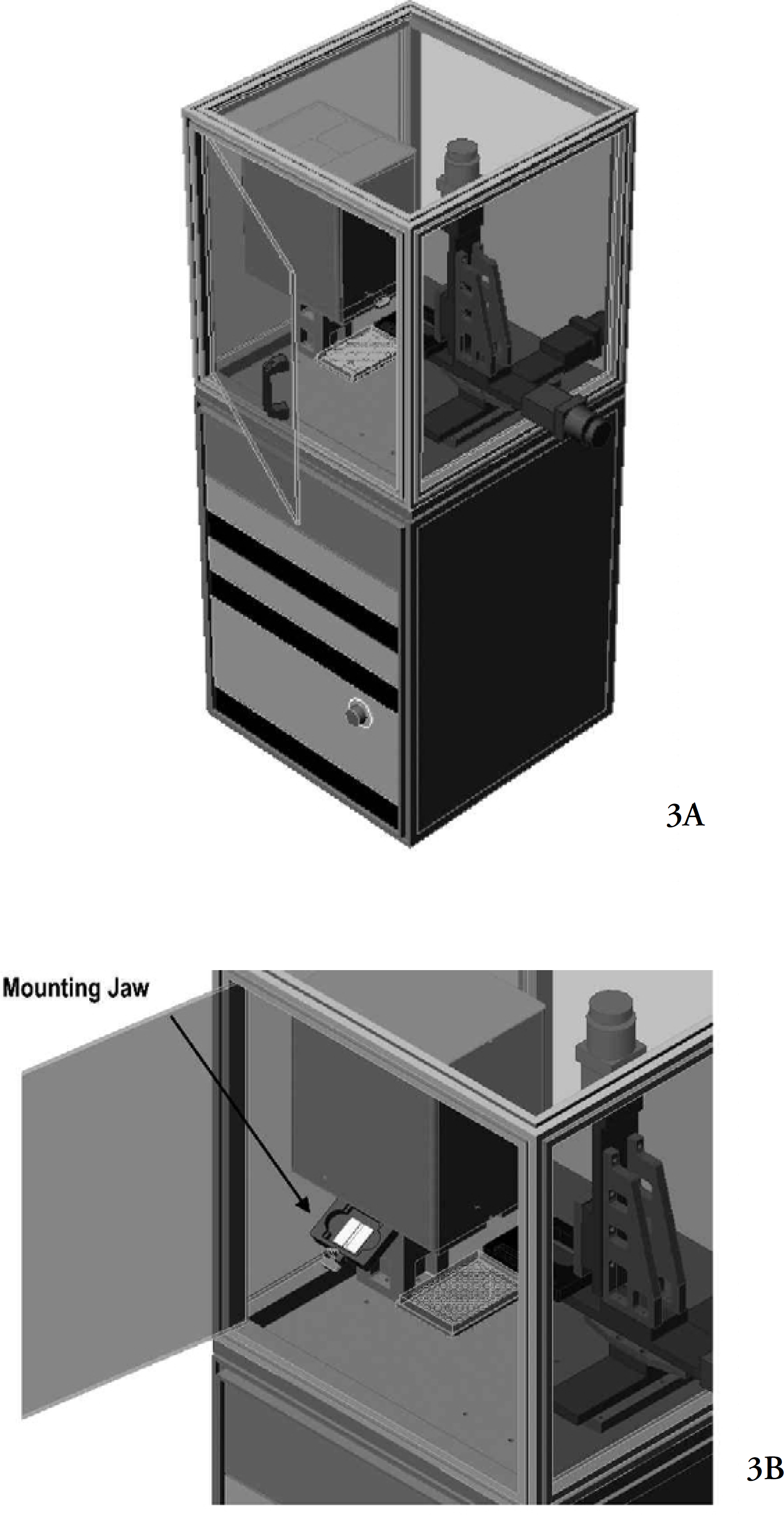
Hardware design of the Caliper AMS 90. The sample plate is mounted on an x-y-z translation stage. The DNA analysis chip is inserted into the mounting jaw (3B), which positions the chip in the chip mount assembly.
LabChip HT, an application running on a PC, automates the DNA analysis process. The application is written entirely in Visual Basic on Windows NT using commercial ActiveX components. The use of Visual Basic allowed rapid prototyping of the user interface. With careful design, the required data throughput and response speed were achieved. The LabChip HT application controls system operation through three subsystems. Subsystem 1 uses an 8-bit controller communicating over a serial port to control the pressure system, which is used for sample loading. Subsystem 2 uses another 8-bit controller through a second serial port connection to control the HV power supply and optical detection. This subsystem is responsible for real-time control of voltages and currents to the DNA analysis chip. In addition, Subsystem 2 controls the excitation laser and an A/D converter for transmission of the LIF signal back to the PC. The x-y-z translation stage is controlled by Subsystem 3, which communicates through an Ethernet connection. The LabChip HT application also includes a state machine to control the timing of the pressure and voltages applied to the DNA analysis chip, a data collection module, and a data analysis module.
Pressing the “Start” button on the Labchip HT user interface begins the fully automated analysis (see Figure 4). During data collection, the fluorescence signal is graphed against time for each sample and is simultaneously shown in a gel-like display (Figure 4). The gel-like display shows data from each row of the plate as a 13-lane gel image, with 12 sample lanes preceded by the associated DNA ladder lane. After each sample has been separated, the data analysis module calculates the size and concentration of each DNA fragment in the sample. The data analysis module smoothes the data, fits a baseline, and identifies the peaks. Using the DNA ladder and the internal DNA marker fragments as reference, migration time is converted to fragment size and peak area to concentration. The analytical results are exportable as a tab-delimited file.
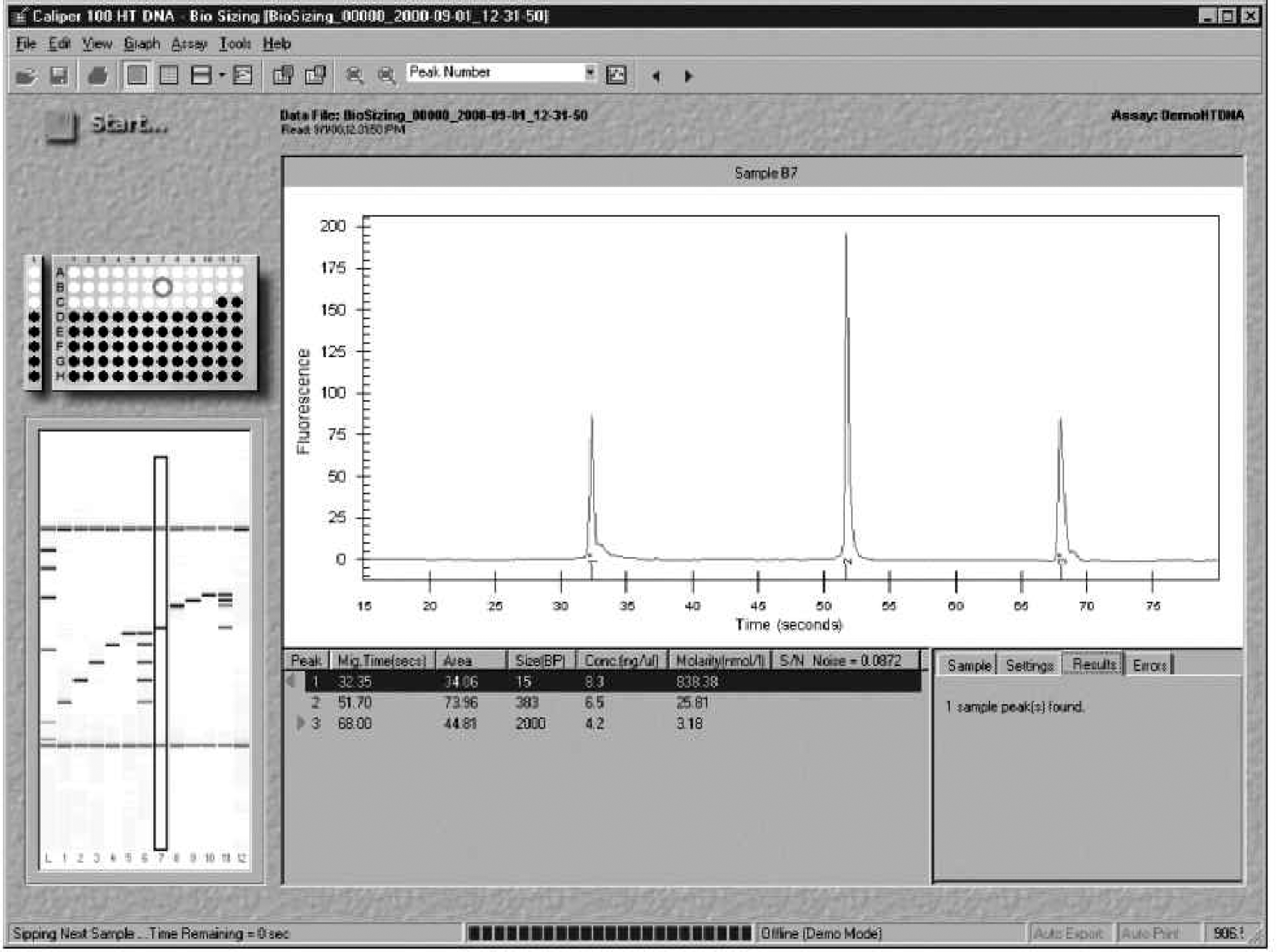
User interface of LabChip HT software. Each analysis is represented as an electropherogram and as a lane in the gel-like image. Analytical results are tabulated below the electropherogram
PERFORMANCE
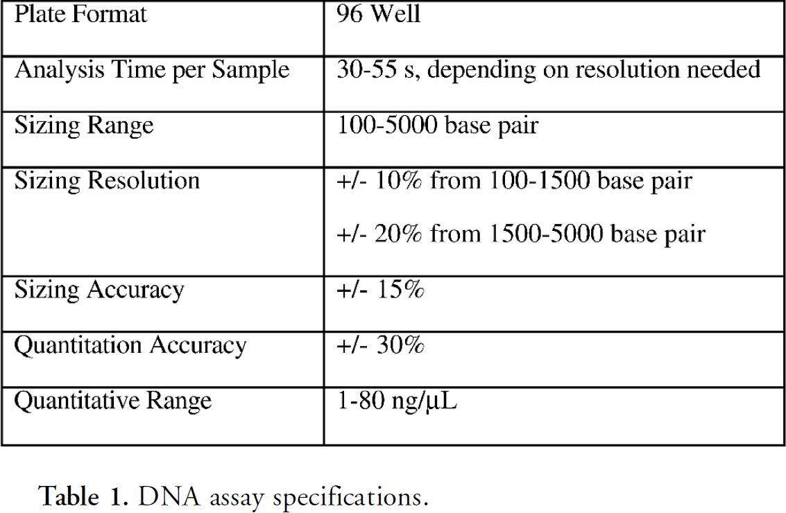
Assay performance specifications are shown in Table 1. To validate assay performance, 43 different DNA fragments from various commercial sources, ranging in size from 100–4870 bp and in concentration from 1–80 ng/uL, were repeatedly analyzed over several day's time. The size and concentration of each fragment was automatically reported by the LabChip HT application. With over 2500 analyzed fragments, sizing specifications were met greater than 99.7% of the time and quantitation specifications were met greater than 99.0% of the time. Because the assay uses a non-denaturing separation, sequence-specific DNA secondary structures occasionally cause anomalous migration. In some cases DNA fragments of similar lengths but different sequences are resolved by the assay's high-resolution separation. For example, the 1353-bp fragment from a BsuRI digestion of ΦX174 DNA (Fermentas, Hanover, MD) migrated at an average apparent size of 1270 bp in our validation study (standard deviation = 41 bp). The reported average size was 6.15% smaller than expected. In contrast, the 1360 bp fragment from the pHY marker (Panvera, Madison, WI) migrated at an apparent size of 1384 bp (standard deviation = 31 bp), or 1.79% larger than expected. We have set the sizing accuracy specification at +/−15% to account for sequence-specific migration. Sizing precision generally is much better, with a typical relative standard deviation of +/− 2% for replicate analyses of an individual fragment. Assay performance was extremely stable over the course of a 96-well sample plate, with no measurable intraplate drift in quantitation or sizing values.
DNA assay specifications.
The standard 55-second assay protocol requires the reagents on the DNA analysis chip to be refreshed after each 96-sample plate to avoid reagent exhaustion. Using this protocol, we typically observe no degradation of assay performance for at least the first 1000 samples analyzed by a chip. An example of typical assay stability is shown in Figs. 5A and 5B. Figure 5A shows an analysis of a BsuRI digestion of ΦX174 DNA using a new DNA analysis chip. Data generated from the same sample on the same chip after more than 1000 samples is shown in Fig. 5B. Peak resolution is virtually indistinguishable between these two analyses. In addition, we observe no systematic drift in sizing or quantitation accuracy during the first 1000 analyses on a chip. Performance typically begins to degrade after about 1200 samples, so we have set the chip lifetime specification at 1000 samples.
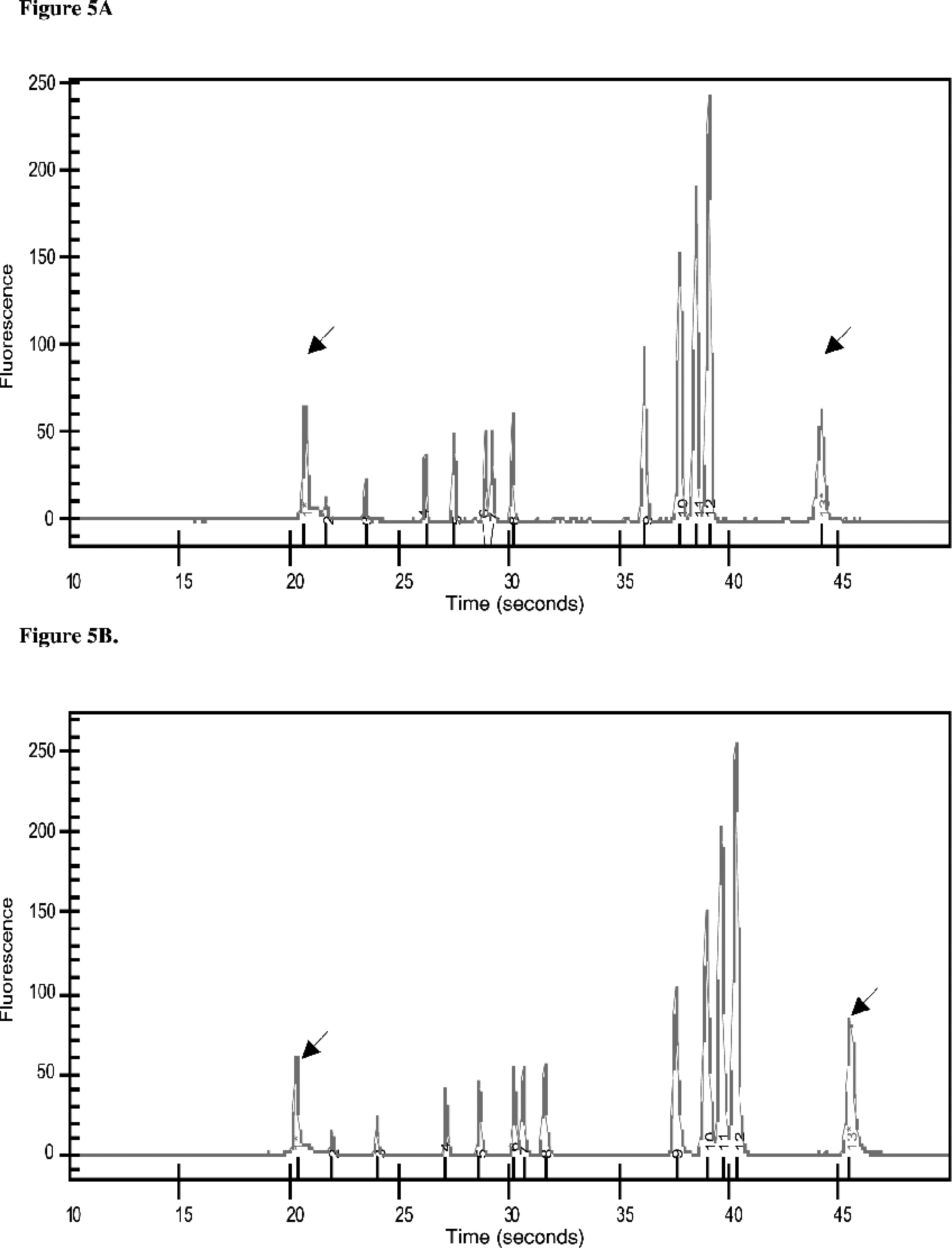
Stable performance for >1000 samples per chip. Figures 5A and 5B show electropherograms of 40 ng/uL of ΦX174/BsuRI DNA. Figure 5A shows the first analysis performed using the chip. Figure 5B shows the 1059th sample on the same chip. The arrowheads denote 15-bp and 7000-bp markers (peaks 1 and 13) that are added to each sample on-chip as internal standards. The intervening peaks are derived from the sample (Peaks 2–12 are 73, 118, 194, 234, 271, 281, 310, 603, 872, 1078, 1353 bp, respectively).
CONCLUSION
Using lab-on-a-chip microfluidic technology, we have designed a system that automates the electrophoretic analysis of DNA fragments in 96-well plates. The Caliper AMS 90 consumes only about 100 nL of each sample and automatically reports the size (bp) and concentration (ng/μL) of all DNA fragments on a plate. Each microfluidic chip reliably analyzes greater than 1000 DNA samples with no degradation in data quality.