
Abstract
Connectivity infrastructure, hardware and software components for point-of-care testing (POCT) environments at medium-to-large sized hospitals with expected number of POCT instruments in the order of hundreds or thousands are described. The instruments include both network-ready and non-network-ready devices. The latter are connected to the network by means of a hardware-based Instrument Network Adapter. Instrument messages are converted to standardized form and, depending on message content, are routed and delivered to appropriate destinations by a software-based Message Routing System consisting of a Message Router and a Delivery Agent. Target information systems consist of departmental and central information systems.
Keywords
INTRODUCTION
Point-of-care testing (POCT) is defined as patient sample testing at or near the site of patient care whenever medical care is needed. 1 The purpose of POCT is to provide immediate information to physicians about a patient's condition, so that this information can be used for diagnostic and treatment decisions resulting in improved patient outcomes, higher patient-perceived quality of care, and/or decreased total care costs. 2
POCT is an important diagnostic and monitoring methodology used at various locations in hospitals, at other health care institutions, in emergency vehicles, at physician offices, and also directly at patient dwellings. 3 The types and sizes of POCT instruments vary widely depending on the technology used, analyses performed, analytes supported, diseases diagnosed, and intended usage patterns and locations. Based purely on their format, the instruments can be categorized as “benchtop”, “transportable”, “portable” or “handheld”. 2
This paper focuses on medium to large hospital environments and mainly on benchtop and transportable POCT instruments deployed locally bedside or in the immediate surrounding areas at care units and medical departments.
The number of POCT instruments and procedures implemented in these environments is growing rapidly especially in critical care settings such as intensive care units, coronary care units and emergency departments where short diagnostic and/or therapeutic turnaround time (TAT) is needed. 4 –6 According to Harvey, 7 the average TAT expected by critical care physicians is 5 to 15 minutes whereas state-of-the-art, highly optimised, air-tube sample transport and electronic result reporting central laboratory systems of today have an average TAT of at least 44 minutes. 8
Furthermore, it has recently been shown 9 that replacing central laboratory testing of blood samples both at an accident and emergency (A&E) department and at an intensive therapy unit (ITU) by POCT decreased total hospital cost from £132,630 to £93,050. This investigation, which was done in a large teaching hospital in England, still did not take into account any eventual savings resulting from earlier diagnosis and from possibly more optimal treatment strategies. Another source estimates in a future-oriented assessment of the role of laboratory medicine that POCT will soon become the most profitable way to provide laboratory services. 10
The above POCT benefits, together with other well-known POCT advantages, 2, 11 and the fact that scientific research and technological development will result in continued expansion of test menus, shorter analysis time, reduced sample volume, and better analytical accuracy and precision, give reasons to believe that the number of POCT instruments at large hospitals will be in the order of hundreds within the present decade. One source estimates the number of currently employed POCT instruments at a typical healthcare institution in the US as “dozens of devices at several locations with hundreds of operators to manage”. 12 The above-mentioned future-oriented assessment of the role of laboratory medicine concludes that the central laboratory of the future is destined to become an esoteric testing centre whereas routine testing at the patient bedside or nearby will become more economical. 10 Should this scenario happen then a large number of POCT instruments, perhaps in order of hundreds or thousands, would be needed at various locations in medium-to-large sized hospitals.
Both manual management of this volume of devices, operators and produced information, including supervision of quality control and assurance procedures, as well as integrating patient test results into departmental decision support systems would be labour intensive and difficult to control and administer. Also, manual administration of test results does not allow realization of the full potential of POCT due to delays between availability of the results at the instrument and their availability to the physician making a diagnostic or treatment decision. However, as recently estimated, 6 only 10 percent of the results produced by the currently deployed POCT instruments are electronically collected and automatically transmitted to the appropriate information systems. Therefore, there is a need for integration of these devices, systems and procedures within hospital network environments using connectivity capabilities available on newer and more advanced POCT instruments. 3, 11 –13
Recently the Connectivity Industry Consortium (CIC) was formed by a number of vendors in the US with the aim of producing and publishing connectivity standards for POCT devices and of evaluating practical applications of the standard. 13–14 Our research and development project, supported by the Swedish Foundation for Knowledge and Competence Development within the “Information Technology in the Health and Clinical Care” programme, 15 started at least one year before the CIC conception and follows the developing standard both at the fundamental conceptual level and at the essential architectural plane. The goal of our efforts is not so much to produce a standard but rather to build a working infrastructure consisting of both hardware and software components to be used in clinical POCT environments at hospitals of today.
INFRASTRUCTURE REQUIREMENTS
The following requirements were identified to be essential for POCT environment infrastructure, its components, and connectivity architecture.
It should be possible to connect non-network-ready instruments to existing hospital local area networks (LAN).
It should not be necessary to furnish any additional plumbing, cables or other point-to-point connections except for the local area network already in place. This should apply even to non-network-ready devices.
The system should not require any instrument-dedicated workstations that need to be installed, configured and managed if the only purpose of such workstations would be connecting a non-network-ready instrument to the hospital LAN.
The system and the communication infrastructure should be clean and easy to manage by using existing network management tools.
On the LAN, at communication levels corresponding to network and session layers of the OSI model, only TCP/IP protocols should be used.
At higher levels, an open, standardized set of protocols and interfaces should be employed. When possible and/or feasible, only one protocol should be used at a particular layer.
When the infrastructure and its hardware and software components are in place there should not be any need for complex, low-level, error-prone communication programming when implementing an application or other software system that uses information provided by the components.
All components should be as inexpensive as possible with proper consideration of component quality which should not be lower than for the other components and devices used in clinical health care in general and intensive care in particular. When applicable, this quality requirement includes the mechanical, the electrical and the electromagnetic properties of the hardware.
Should any system component need to be customized for a new instrument type or vendor then such a customisation should be relatively simple (simpler than required today) in terms of labour and time. It should be possible to make such customisations on the fly without bringing down vital or central system parts.
The system should be built for unattended, continuous, 24-hour, 7 days a week operation.
It should be possible to centrally manage and supervise quality control tests and their results for the whole hospital, and to some extent, automatically enforce quality assurance policies.
It should be possible to monitor the results of central processing of quality control test data from a client computer connected to the network at an arbitrary physical location within the hospital subject to security and privacy policies established by legal and hospital regulations.
Contrary to quality control test data, patient test results should be conveyed to local and departmental information and decision support systems where the data should be pre/post-processed in such a manner that the results originating from different instruments could be regarded as comparable and compatible with respect to measured levels and accuracy, i.e. the data should be concordant between the devices over time.
It should be possible to monitor and track patient test results together with other processing results and with appropriate diagnostic range indications from a client computer connected to the network at an arbitrary physical location within a department subject to security and privacy policies established by legal, hospital and departmental regulations.
The above list of requirements does not pretend to be exhaustive or complete. It simply represents a starting point for research, design, and actual construction of our POCT connectivity infrastructure environment.
INFRASTRUCTURE OVERVIEW
An overall POCT environment system infrastructure is depicted in Figure 1. The thick black line represents a shared hospital-wide LAN. A number of devices are connected to this network. The devices consist of appropriately equipped analytical instruments, various servers and user workstations (clients).
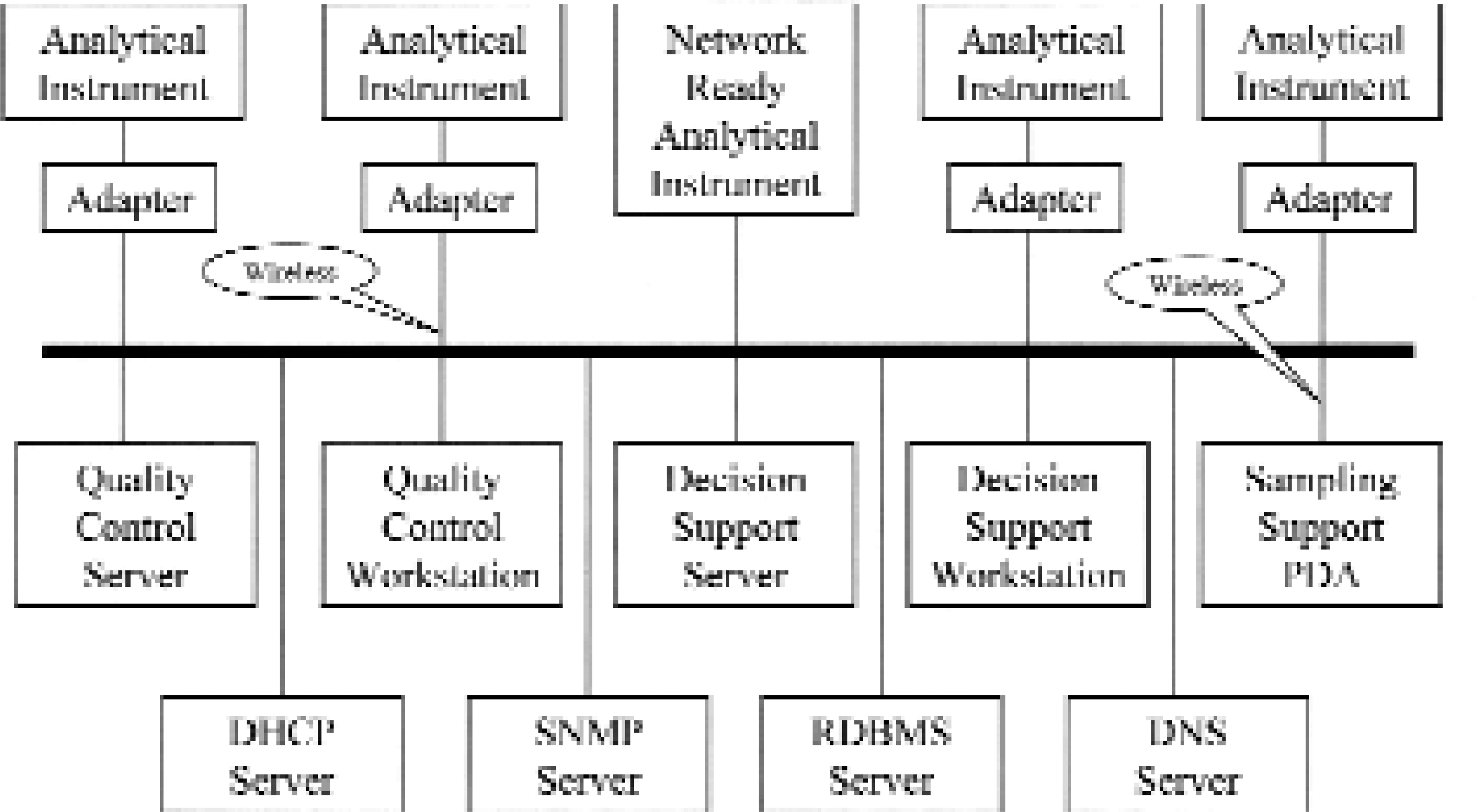
Non-network-ready instruments that support only serial communications are connected to the LAN using an Instrument Network Adapter. Some other instruments are already network-ready and do not need the adapter. Yet other instruments are mobile and will use a wireless adapter.
On the network there also are a number of servers providing various services. Note that in this case a box in the drawing does not need to correspond to a physical server computer. Rather it represents a service such as server software running on a computer and handling a particular task. The services that run on particular servers is a matter of configuration that may change over time. At small sites and installations there will be few servers running multiple services each. At large sites with hundreds of instruments and workstations there could be one-to-one relations between server machines and services.
The Quality Assurance Server is a central hospital service that gathers quality control test result data from all the instruments and provides an implementation of Quality Assurance procedures, policy enforcement, and monitoring. The received quality control test result data are processed by a number of selected statistical quality control procedures that represent the current quality assurance policy of the hospital. The procedures use a database containing information about all connected hospital instruments, quality control levels and analyses, and used control materials.
Quality Assurance Clients allow for displaying and monitoring of quality assurance results. These clients are also used for maintaining the above mentioned quality assurance database with respect to instruments, rules, levels and control materials.
Decision Support Servers are departmental servers processing and storing patient test result information from instruments in their respective departments. The raw test result data received from an instrument are pre- and post-processed with respect to analytical bias so that the resulting information is concordant between instruments over time. Further information processing is department and disease specific. Decision Support Servers also store information about submitted patients and patient samples, and maintain associations between patients, samples, tests and time.
Decision Support Clients provide more or less real-time display of information pre- and post-processed by the Decision Support Server at a department. The exact nature of this information and the form used for its display is of course department and disease dependent. Some of these clients are also used for entering and/or modifying patient information when submitting and/or discharging the patients and when working with integrated patient records stored at a corresponding DSS server.
Sampling Support PDA's are handheld devices based on commercially available palm-sized Personal Digital Assistants suitably equipped with barcode and/or smartcard readers and with wireless communications. These devices facilitate the work done by physicians, nurses, and particularly by sample-drawing personnel, and are used in order to minimize errors in correlation between patients, samples, tests and time that otherwise could occur when manually entering patient and sample id-numbers and sample-drawing time into the instrument panels and into information systems.
In addition to the above clinical layer of services there are a number of common basal network services such as Dynamic Host Control Protocol (DHCP) service, Simple Network Management Protocol (SNMP) service, Relational Database Management System (RDBMS) service, Domain Name System (DNS) service and the other well-known LAN and Internet servers and services on the network.
INFRASTRUCTURE ANALYSIS
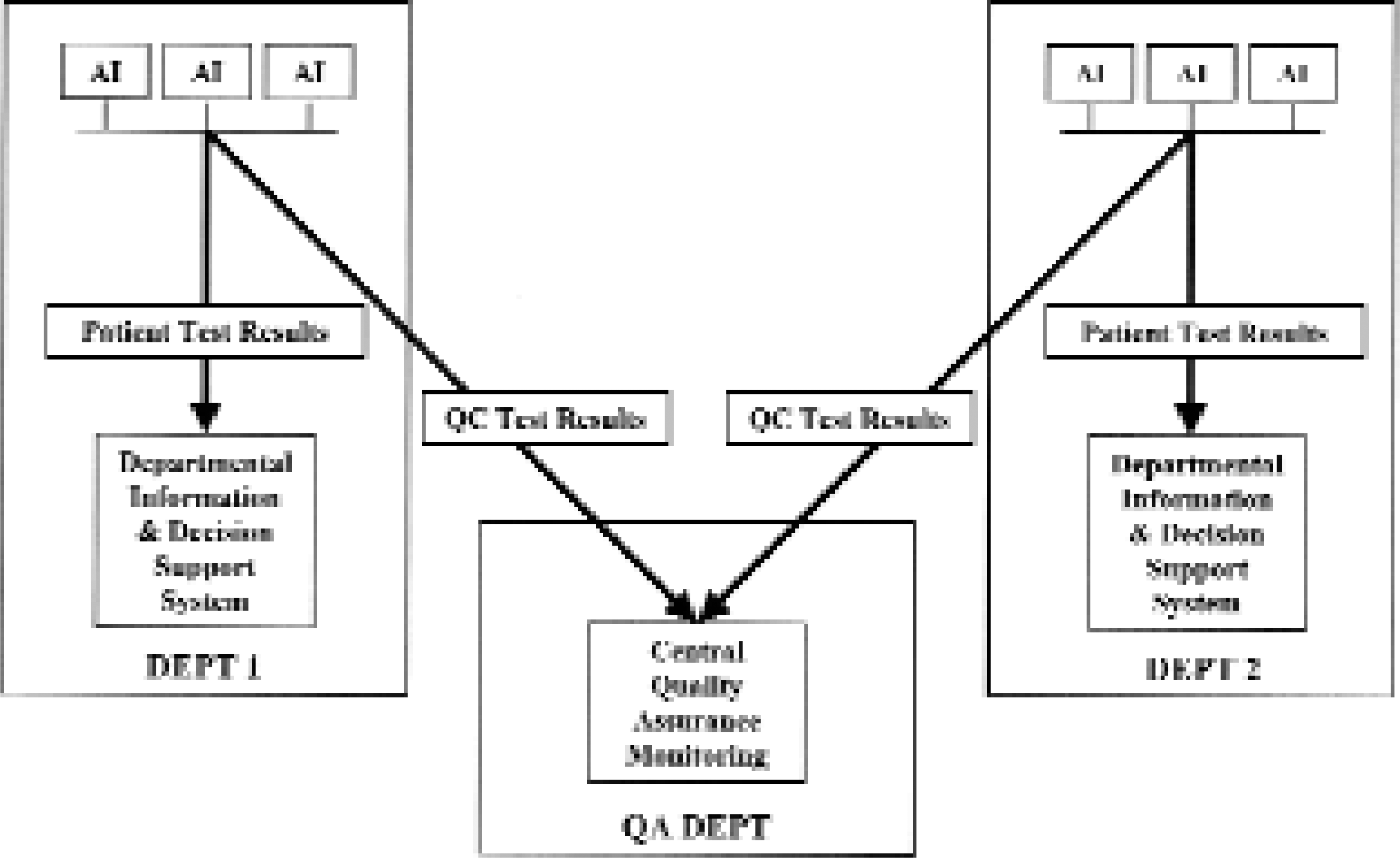
Careful analysis of the above infrastructure and of what it will be used for reveals the need for yet another network service. A medium-to-large sized hospital campus usually consists of a number of departments, units and buildings represented in Figure 2 by DEPT 1 and DEPT 2. Each unit contains a number of networked instruments, annotated AI (analytical instrument) in the figure. Depending on capabilities, the instruments are connected to the LAN either via a network adapter or directly using instrument built-in network interface. A departmental Information and Decision Support System (DSS) supports the health care work in each department.
POCT Instruments Sending Information
Centrally at the hospital there is a department that is responsible for quality assurance of all hospital instruments including POCT instruments at the various departments. This department, annotated QA DEPT in the figure, which may be a part of an existing Clinical Laboratory department, operates the Quality Assurance Server software in order to provide QA services to the other departments and in order to enforce certain QA policy in the hospital.
Therefore, virtually, each instrument should send the test results to at least two different destinations. Patient analysis test results should be sent to a departmental DSS system whereas quality control test results should be sent to the central QA server as shown in Figure 2.
In order to do this and still keep a clean and easy manageable infrastructure there is a need for a special service called a “message converter and router” and software called a “delivery agent”. The router forwards appropriate messages to appropriate destinations and the delivery agent delivers the information to corresponding information systems. This is depicted in Figure 3.
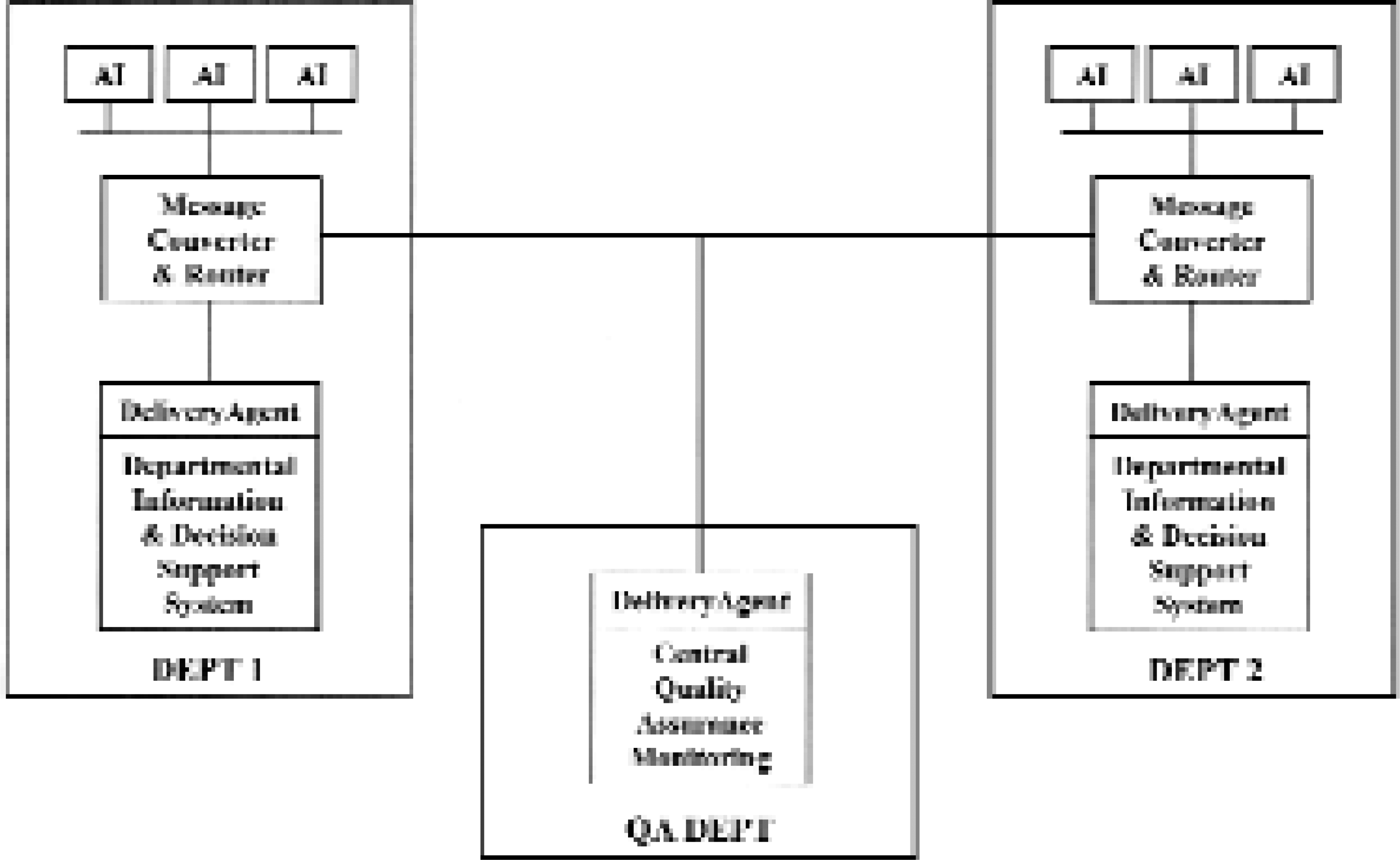
POCT Message Routing System
In addition to the routing function, the message router service is also an appropriate place to transform test result messages from instrument and vendor dependent form, content and protocol to a common, vendor independent high level and unambiguous representation.
MESSAGE ROUTING SYSTEM
As mentioned above, the Message Routing System consists of message router service and delivery agent software. The router receives instrument messages from the network - directly or via the Instrument Network Adapter - and routes each message to the targeted information system, e.g. a departmental Decision Support server or a central Quality Assurance server depending on message content. The router recognizes instrument type and vendor dependent high level protocol variant (low level is TCP/IP socket stream) and it decodes the messages by using instrument vendor and type specific decoder. Decoders are small software objects that are loaded dynamically on an as-needed basis. By using information provided by a decoder, a message is converted to an internal standardized and instrument vendor and type independent object storage format. If the created message object contains quality control test results or other quality control or instrument monitoring related information such as instrument alarm or calibration results then the message is routed to the central QA server. If the message object contains patient test results then it is routed to the departmental DSS server. Figure 4 displays a simplified UML Class Diagram for a part of the Message Router classes' framework.
The Listener class constitutes the Message Router service main entry point. When the service starts on a server then a Listener object instance is created. This Listener object listens to incoming TCP/IP connection requests sent either by a network-ready instrument or by an Instrument Network Adapter connected to a non-network-ready instrument. When such a request is detected the Listener establishes a TCP/IP session with the requestor, and creates a new Router object on a separate thread of execution, and passes the session socket to it.
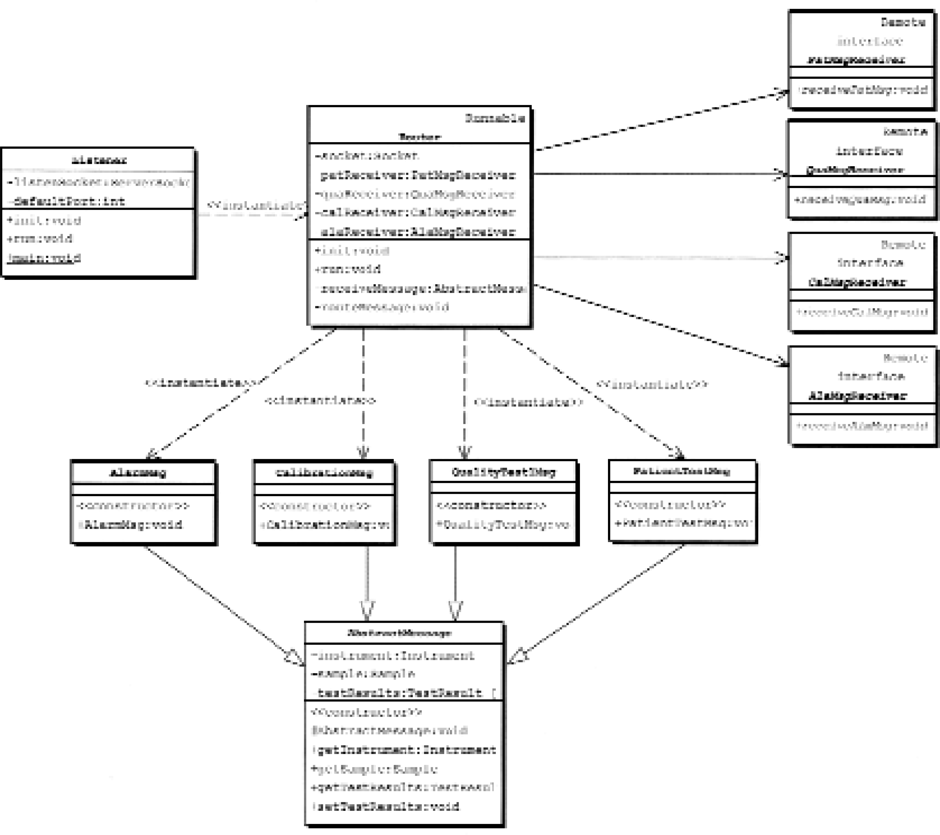
The Router object reads a message sent by an instrument. It parses the message with help from an instrument specific decoder object (not shown) and stores the message in an appropriate message object that uses a format independent of the actual instrument type and vendor. Patient test results are stored in an object of class PatientTestMsg and quality control test results are stored in an instance of class QualityTestMsg. Both these classes inherit from the class AbstractMessage that gathers properties and methods common to both message types. Then PatientTestMsg objects are sent to departmental DSS servers by using the PatMsgReceiver interface, whereas QualityTestMsg objects are sent to the central QA server by using the QuaMsgReceiver interface. Instrument calibration (class CalibrationMsg) and instrument alarm (class AlarmMsg) messages are handled in a corresponding manner and are sent to the target system using interfaces CalMsgReceiver and AlaMsgReceiver.
Routed messages arrive at their destinations as standardized CORBA objects. 16 The Router uses OMG Objects-by-Value technology 17 in order to minimize network traffic, which means that not only object references are sent as is done in “plain” CORBA but also that the whole objects are transferred to the target system where the objects may be operated on without causing network access. The communication interfaces are defined using Interface Description Language (IDL) and use the standardized CORBA/IIOP protocol on the network. Therefore the messages can be received by any CORBA compliant environment, which today includes most of the popular operating systems and programming languages.
The router software is 100% Pure Java. 18 It uses the Java Language to IDL Mapping 19 and Remote Method Invocation over IIOP (RMI/IIOP). 20 It therefore runs on any Java supported platform and can communicate with any CORBA compliant message receiver (delivery agent).
The Delivery Agent (Figure 3) functions as a bridge between the standardized message infrastructure and target information systems, e.g. a DSS or a QA system, vendor-dependent technology so that a variety of information systems from different vendors using disparate technologies could be employed in this infrastructure. The agent receives the standardized CORBA messages from the router. It delivers the received information to the target system using logically standardized content. However, it uses target system dependent delivery technology, which very often is a database record. This arrangement makes both the content and the form of delivered information independent from the originating instrument type, vendor and protocol. Currently used delivery agents are all written in Java. However, it is possible to use any programming language supported by the CORBA specifications.
For Quality Control Test Results the delivered information consists of the following items:
Information about the message itself:
Message sequence number
Message delivery timestamp
Information about the sending instrument:
Instrument vendor ID
Instrument model ID
Instrument serial ID
Information about the control material:
Control material type/vendor ID
Control material batch/lot ID
Control material level ID
Control material insertion/processing timestamp
Information about performed test:
Test ID
Test timestamp
Information about test result:
Test result value
Test result unit
The delivery agent creates the above information about the message itself. Information about the sending instrument is either fully supplied by the instrument within the original instrument message or is synthesized by a network adapter and/or the message router based on information available within the original message and instrument knowledge encoded into a particular network adapter and/or into a particular instrument type dependent message decoder.
For some control materials and instrument types, the information about the control material type/vendor ID, batch/lot ID and level ID is originally encoded into the sample ID and is scanned at sample insertion time by an instrument's barcode reader or is entered manually via an appropriate instrument panel. This sample ID is sent within the original instrument message to the message router where it is decoded back into separate fields. This scheme is used for QC materials and runs where the QC sample is external to the instrument and therefore it is handled in a way analogous to a patient sample. For some other control materials and instrument types, the instrument provides this information automatically within the original message in an instrument vendor and type dependent way. This scheme is used for QC materials and runs where the QC samples are stored within an instrument and QC runs are performed automatically by the instrument without manual intervention. Control material insertion or a processing timestamp is often available within the original instrument message. If not, then a network adapter or the message router synthesizes it by using message send or receive timestamp. This is vital information because it allows one to keep track of the number of tests and test results that may be sent separately as a result of one particular control sample analysis and to associate these results with that very sample and with that particular quality control run.
Information about the performed tests and test results is usually contained within the original instrument message. For certain instrument vendors and models some parts may be missing in which case these data are synthesized by the message router based on default values for the actual instrument vendor, model and the performed analysis. The instrument type dependent decoder described above adds appropriate values for the missing parts as required.
All this processing results in the delivered information being unified, standardized and entirely independent of the sending instrument. The idea here is that the receiving information system (e.g. a QA or a DSS system) should not need to process the information in an instrument or control material dependent way. It may of course need to use the instrument serial ID to pickup an instrument dependent control limit or use the control material ID, level and batch to pickup material dependent control limits from a database when evaluating QA rules, but this will still be instrument and material independent processing as long as it is done equally for all instruments and all materials. All instrument dependent processing is done within an instrument type specific decoder dynamically loaded on an as-needed basis by the message router and/or by a network adapter connected to a particular instrument. The message router uses a special algorithm to associate a particular decoder (dynamically loaded Java class) with an instrument vendor and model specified within the original message. A network adapter is connected to a particular instrument and therefore it “knows” the peculiarities of that instrument, and may transform the information in an appropriate way.
For Patient Test Results the delivered information is similar to the above except that information about the patient sample replaces information about the control material.
INSTRUMENT NETWORK ADAPTER
The Instrument Network Adapter operates as a gateway between non-network-ready instruments and the network. The adapter transparently forwards data and control messages and information from an instrument to the other devices on the network. It also forwards all messages addressed to the instrument from the network to the instrument itself. Figure 5 shows two analytical instruments. Each instrument is connected via a serial line to a corresponding adapter. Each adapter is connected to the hospital LAN. Somewhere on this LAN there is a computer, which uses TCP/IP to communicate with the instruments with the help of the adapters.
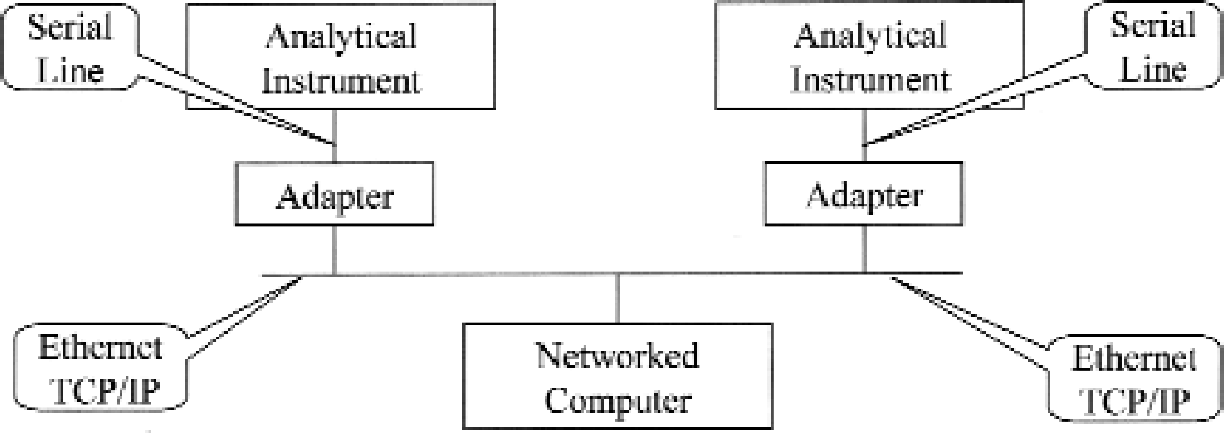
POCT Instrument Network Adapter Function
Obviously, non-network-ready instruments can be connected to the network through an adapter. The instruments can be centrally managed, controlled and supervised (including quality assurance), and can communicate with other systems and devices over the network. By using the adapter the need for additional plumbing and point-to-point cables is eliminated because the adapter is placed in the immediate vicinity of an instrument and connects to the LAN already in place. Instrument dedicated workstations that could be expensive to install, manage and configure, and that require non-negligible physical real estate bedside or on the benchtop which is not always available can be avoided if not needed for other than connectivity reasons. Moreover, the resulting communication infrastructure is clean and easy to manage using existing network management tools e.g., Simple Network Management Protocol (SNMP) tools and various other network and packet analyzers. Among other things, only one standardized protocol (TCP/IP) is used and therefore complex, error-prone, low-level communication programming on the receiver side is not necessary because virtually all operating systems today have a built-in TCP/IP stack of good quality.
The external details of a working prototype for the Instrument Network Adapter hardware device are described in Appendix 1. The usual serial EIA CITT RS-232 line connects an instrument with the adapter. The prototype has been tested for up to 115 kilobits per second transmission rate in continuous, around-the-clock operation. The communication with an instrument is done today using ASTM 1381-95, Low-Level protocol 21 that is supported by a large number of existing instruments. Other low level protocols are under development. The Low Level protocol acts as a bearer for a highlevel protocol payload. A payload consisting of ASTM 1394-97, High-Level protocol 22 is fully supported as well as CEN standard ENV 13728, High-Level protocol. 23 All other high level protocols are also transparently forwarded to/from an instrument.
The adapter connects to the network using Standard Ethernet 10Base2 Thin Wire BNC connector and/or Standard Ethernet 10BaseT Twisted Pair RJ-45 connector. Standard TCP/IP streams/sockets are used on the transport/session protocol levels when communicating with a computer on the LAN. Both the above ASTM and CEN High-Level specifications are fully supported on the network side as well as any other high-level protocol forwarded from/to an instrument.
The adapter runs a specially modified version of the Linux operating system. 24 The modifications consist mainly of selecting a minimal set of Linux kernel modules that satisfy requirements of the adapter, compiling the selected kernel source code, and building an executable Linux kernel suitable for embedding into the adapter. Some minor modifications to the bootstrap code and serial port initialization were also necessary. A large amount of work went into figuring out which of the hundreds of supporting libraries, programs and files that normally are present on a Linux (or other operating systems) installation were required in order for the kernel to run properly and in order to support the network gateway software. It is the full set of these libraries, programs and files together with the kernel that is called “operating system”. Because of the complexity of the interdependence among, and large number of, these modules, the only practically feasible way to make a proper selection was an iterative and experimental trial and-error approach described below.
A naked Linux kernel image was bootstrapped on the adapter hardware and immediately complained about some missing library, process or file and died before it actually booted up. During the very first attempts the system simply died without even telling why. Intelligent guessing was then used to select a possible candidate module for the missing one and the experiment was repeated until the correct missing module was found. Next the whole process was repeated again, this time having a kernel and one of the required modules, which eventually yielded a second required module. This was then repeated until all required modules, libraries, programs and files were found. Very often a newly found module was dependent on yet another module that had to be found before the first one could be used. For each experiment a bootstrap “distribution” had to be prepared on a development machine running full Linux system and then this distribution was used to bootstrap the adapter. The work turned out to be easier and faster after networking, the Remote Procedure Calls (RPC) client, the Network File System (NFS) client, and the Flash File System driver became functional on the adapter. Now the network communication could be used in order to install new modules on the adapter and going through the whole bootstrap process for each experiment was no longer necessary. After virtually endless iterations, and in some cases heavy modifications to system scripts, we obtained a minimal set of operating system modules that fulfilled our needs.
The result is a multitasking operating system that requires less than 4 MB RAM memory and less than 4 MB flash memory disk for its operation, and that boots within a few seconds. The system simultaneously runs TCP/IP and serial communications, DHCP, DNS, RPC and NFS clients, INETD, FTP and Telnet servers, interactive Bourne shell and, of course, the gateway software. Using no more than a 486 class 66 MHz CPU the software is able to continuously sustain a serial communication rate of 115 Kbps with simultaneous forwarding of ASTM or CEN High-Level packets to a receiver on the LAN. Thanks to GNU licensing, all the software was available in source code form and completely free of charge. In fact all the software running on the adapter was compiled and built from the corresponding source code on our development system.
On top of that, the Instrument Network Adapter gateway software was written from scratch. As mentioned before, the software converts between ASTM Low-Level protocol and TCP/IP streams in both directions. Support for other low level protocols is under development in the form of plug-in modules. The software configures itself using a DHCP server on the network. Received configuration data consist of the usual IP parameters, serial port parameters and IP address of the ultimate message receiver. The adapter can participate in SNMP management domain and therefore it can be managed and supervised by the usual SNMP tools. The adapter also runs stripped down versions of FTP and Telnet servers that make it possible to maintain and upgrade the software over the network. All software resides on a standard Compact Flash memory card that can be easily replaced should the need arise.
Main software modules and architecture are depicted in Figure 6.
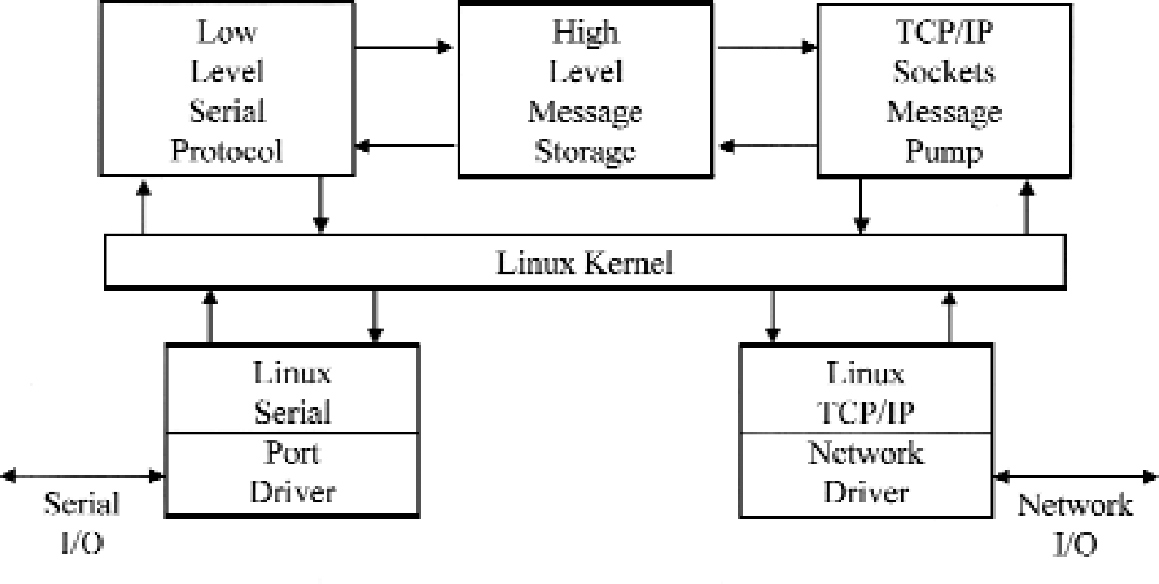
The Linux kernel provides multitasking, high performance, a small footprint, and a resource efficient and extremely stable operating environment. The Linux serial port driver provides for serial port control and the basal capability of transmitting and receiving serial characters. The Linux TCP/IP stack, together with an appropriate network driver, allows for reception and transmission of IP packets and establishment of TCP sessions. These modules are freely available GNU licensed software that was specially adapted for our needs.
The box labeled Low Level Serial Protocol implements bi-directional ASTM Low-Level protocol driver. The High Level Message Storage box is a protocol-independent message storage module. Finally the TCP/IP Sockets Message Pump module transmits and receives High-Level messages to/from the network using the TCP/IP sockets mechanism.
SUMMARY
The overall intent of POCT is to reduce the total process time from a decision to request a test, to availability of result, and to the management decision based on the test result, i.e. to reduce diagnostic and/or therapeutic TAT. 11 This should be done without compromising the quality of the analyses and their results, which implies performing and monitoring of QC tests and procedures. 6 The full potential of POCT in this respect will not be realized unless the system components, i.e. instruments, decision support systems, quality assurance systems, laboratory information systems and hospital information systems, some of which are centralized while others are distributed, work in unison with full and automatic real-time connectivity and in an integrated and trouble-free environment.
Given the variety of instruments, communication protocols, information systems and databases already in use at medium to large size hospitals and also the scale of such an enterprise in terms of numbers of patients, instruments, analyses, decisions, personnel and overall logistics, the correct, general, scalable, flexible and foresighted infrastructure in which these components cooperate and communicate is vital for realization of such an environment. Layered architecture (one component does only one thing but does it well) and clearly defined and general interfaces between the components of this infrastructure are essential for its long-term success, cost-efficiency, robustness and manageability.
The already mentioned Connectivity Industry Consortium is working towards standards that when fully defined, accepted and generally implemented could be employed when building this infrastructure. Our approach however is to research and develop a system that allows existing components to cooperate and communicate despite different interfaces, protocols and capabilities.
We have done that by incorporating a layer of middleware components both at the hardware and the software levels that have the ability to dynamically adapt themselves to various communication protocols and information representations and to translate this information from/to a particular and more or less proprietary representation to a standardized format used when conveying the information between two middleware components. When two proprietary devices or systems communicate with each other there are always at least two middleware components in between. First, a middleware component translates between the format of the first device and the standardized format, and then the information is conveyed to the second middleware component, which then translates between the standardized format and the format of the second device/system.
The described infrastructure is currently used on a daily basis in the clinical intensive care and in full-production environment at the Uppsala University Hospital, which is one of the three largest hospital campuses in Sweden. The system is continuously evolving and improving as a result of the research and a better understanding of the needs of, and requirements posed by, such a distributed laboratory and decision support information system which itself is a consequence of deployment of POCT methodology at hospital departments and institutions.
CONCLUSION
Health care in general, and hospitals in particular, are facing a transition from central laboratory systems to distributed point-of-care systems. At the same time a transition is occurring from standalone, or in some cases almost manual decision support systems, to fully integrated but distributed electronic health care systems that to a large extent will take over the function of traditional LIS, HIS and DSS systems. 6, 10, 25 This transition, which will take place during the next 10 years or so, parallels the transition from Central Host and Terminal Computer systems to Distributed Networked Client and Server systems that has taken place within the enterprises around the world during the last decade. The main experiences gained during the transition that already has taken place are:
Without planning, standards and correct infrastructure you don't get a well working system but a mess.
What should be distributed are information processing and retrieval and the work associated with them.
What should be kept centralized are systems management, control and supervision.
Therefore we need tools and software for such centralized management of distributed systems.
In our opinion this experience and knowledge is without doubt applicable also when building systems for the e-laboratory and e-healthcare of the future and should be utilized to its fullest potential.
ACKNOWLEDGEMENTS
Large parts of this work were performed within the Swedish Foundation for Knowledge and Competence Development programme “Information Technology in Health and Clinical Care” project “IT-support for Quality Assurance of Decentralized Instruments”. The support from the participating enterprises, SYSteam Udac AB, Uppsala, Sweden and Datakonsulten AB, Ludvika, Sweden is also gratefully acknowledged.
We would like to thank Mr. Ove Larsson, SYSteam Udac AB and Associate Professor Bo Sandhagen, Uppsala University Hospital for their invaluable comments and many engaging discussions.
Last but not least we would like to express our gratitude to Dr. Linus Torwalds and all other GNU and Linux people involved in construction, distribution and documentation of the software for sharing the results of their work with the rest of the world for free.
APPENDIX 1
Figure 7 shows a photograph of the exterior of the actual hardware prototype for the Instrument Network Adapter.
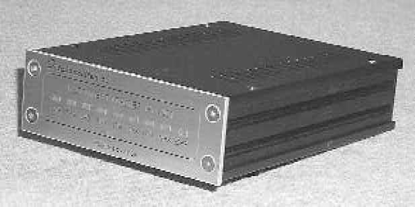
POCT Instrument Network Adapter Prototype
The device is housed in a commercially available plastic-coated metal instrument box measuring 127 × 45 × 177 millimeters. In an industrial production version this size could be easily reduced to one fourth. The box itself provides physical protection for adapter electronics, serves as a heat dispatcher, and also shields the adapter and its external environment from each other's electromagnetic radiation. The front panel contains a number of Light Emitting Diode (LED) indicators used for diagnostic and monitoring purposes described below. All the connectors are placed on the rear panel, which is not visible in Figure 7.
A closer photograph of the Instrument Network Adapter prototype front panel is shown in Figure 8.
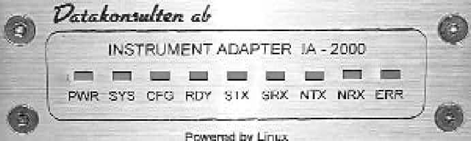
POCT Instrument Network Adapter Front Panel
The nine rectangular LED diagnostic indicators function as follows.
PWR lights up as soon as the adapter is connected to the electric power source.
SYS lights up when adapter's operating system has completed the boot up sequence.
CFG goes up when the adapter has configured itself using a DHCP server on the network.
RDY goes up when the adapter is ready to forward messages from/to connected instrument.
STX flashes when the adapter is transmitting a message to the instrument over the serial line.
SRX flashes when the adapter is receiving a message from the instrument via the serial line.
NTX indicates message transmission to the network.
NRX indicates message reception from the network.
ERR lights up when some errors in communications are detected.
All LED indicators are green except ERR indicator, which is red.
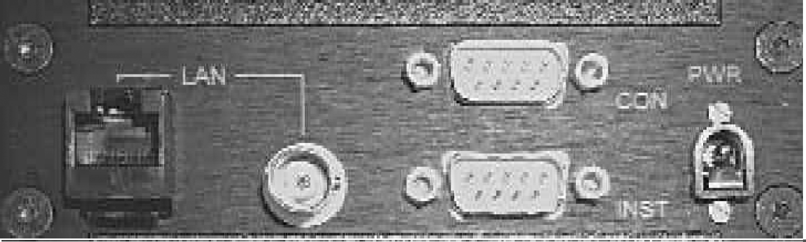
The connectors and sockets are placed on the adapter's rear panel shown in Figure 9.
From left to right the connectors are as follows.
LAN - Twisted Pair Ethernet LAN RJ-45 connector.
LAN - Thin Wire Ethernet LAN BNC connector.
INST - First serial port where an instrument is connected.
CON - Second serial port that is used for debugging and maintenance.
PWR - Power connector is used for the electric power source.
In summary, the Instrument Network Adapter is a cheap (when produced in sufficiently large quantities), small and maintenance-free device that does not contain any moving or rotating parts or forced cooling. The adapter does not need any special set-up, configuration or installation. The adapter is a “plug in and run” device that operates in unattended 24×7 continuous mode.
Footnotes
Appendix
NCCLS AUTO6-P, Point-of-Care Connectivity; Proposed Standard, was developed for those engaged in the manufacture of point-of-care diagnostic devices including the hardware and software used to connect the devices to various information systems in healthcare facilities. The proposed standard incorporates the work product of the Connectivity Industry Consortium (CIC), an organization that developed specifications for point-of-care device and information system communication interoperability. It provides the basis for multi-vendor, seamless interoperability between point-of-care devices, data managers, and clinical results management systems. This proposed standard provides the framework for engineers to design devices, work stations, and interfaces that allow multiple types and brands of point-of-care devices to communicate bi-directionally with access points, data concentrators, and laboratory information systems from a variety of vendors.
Tests that had been previously limited to the domain of central laboratory analyzers are now available in a variety of care settings. Sophisticated tests are possible at the hospital bedside, during patient encounters in primary- and secondary-care clinics, and even in the home. This new Point-of-Care diagnostic device class offers the advantages of fast turnaround time for test results and the possibility of cost reduction for some tests. In general, a diagnostic test is not differentiated based on where the test is performed. Someone in the institution, however, must be able to show that the test was performed in compliance with the policies of an overall diagnostic testing quality system for the institution. It is thus incumbent upon Point-of-Care diagnostic device vendors to offer mechanisms by which their devices may be integrated into an institution's diagnostic information management system. It is this requirement for data integration that drives the need for industry standardization and the development of this standard.
The Point-of-Care Connectivity Industry Consortium (POC CIC) was established in October 1999 and, beginning with its kickoff meeting in February 2000, worked within a “fast-track” model and developed the Point-of-Care diagnostic integration specification within the CIC's planned 12- to 15-month lifetime. The CIC organization then handed the specification to NCCLS (www.nccls.org), Health Level 7 (www.hl7.org), and IEEE (www.ieee.org) organizations for subsequent maintenance and extension.
This document integrates the work product of the CIC into the NCCLS format and standard development process. The development of AUTO-6P, a proposed standard, has undergone a rigorous 15 month development, review, and balloting process by the 60 members of the CIC who have voted in the affirmative for the specifications and the sunseting of these specifications with NCCLS. Consequently, the Board of Directors of NCCLS chose to accelerate the review period by the NCCLS membership and shorten the review period of the Proposed Standard to 60 days. NCCLS has distributed the Proposed Standard to the NCCLS membership for review and comment on this important and significant contribution to standardization of connectivity in Point-of-Care Diagnostics. The Committee on Point-of Care Connectivity chose to send this document to NCCLS members on a CD. To that end, approximately 1,000 CD's, containing the proposed standard and comment form, were distributed on May 21, 2001 to NCCLS members for their review and comment during the next 60 days until July 21, 2001. The Proposed Standard is also accessible on the NCCLS website.
The POC Connectivity Committee will meet weekly until July 28, 2001 to review and resolve the comments that are received. It is the Committee's intent to complete the commenting and resolution of comments by July 21, 2001 and vote on the standard for publication at the approved level on July 28, 2001 at the AACC National Meeting in Chicago. Once approved by the POC Committee, the Area Committee on Automation will also vote on the standard and once approved will forward the standard to the NCCLS Board of Directors for final approval. The POC Connectivity Standard should be published as an Approved Standard by year end. This is a beginning and should provide the basis for the development of additional POC standards for quality assessment programs, use applications and other pertinent areas as the technology continues to develop.
Jeffrey A. DuBois, Ph.D.
POC Connectivity
Committee Chairman
NCCLS AUTO6-P,
Tests that had been previously limited to the domain of central laboratory analyzers are now available in a variety of care settings. Sophisticated tests are possible at the hospital bedside, during patient encounters in primary- and secondary-care clinics, and even in the home. This new Point-of-Care diagnostic device class offers the advantages of fast turnaround time for test results and the possibility of cost reduction for some tests. In general, a diagnostic test is not differentiated based on where the test is performed. Someone in the institution, however, must be able to show that the test was performed in compliance with the policies of an overall diagnostic testing quality system for the institution. It is thus incumbent upon Point-of-Care diagnostic device vendors to offer mechanisms by which their devices may be integrated into an institution's diagnostic information management system. It is this requirement for data integration that drives the need for industry standardization and the development of this standard.
The Point-of-Care Connectivity Industry Consortium (POC CIC) was established in October 1999 and, beginning with its kickoff meeting in February 2000, worked within a “fast-track” model and developed the Point-of-Care diagnostic integration specification within the CIC's planned 12- to 15-month lifetime. The CIC organization then handed the specification to NCCLS (www.nccls.org), Health Level 7 (www.hl7.org), and IEEE (www.ieee.org) organizations for subsequent maintenance and extension.
This document integrates the work product of the CIC into the NCCLS format and standard development process. The development of AUTO-6P, a proposed standard, has undergone a rigorous 15 month development, review, and balloting process by the 60 members of the CIC who have voted in the affirmative for the specifications and the sunseting of these specifications with NCCLS. Consequently, the Board of Directors of NCCLS chose to accelerate the review period by the NCCLS membership and shorten the review period of the Proposed Standard to 60 days. NCCLS has distributed the Proposed Standard to the NCCLS membership for review and comment on this important and significant contribution to standardization of connectivity in Point-of-Care Diagnostics. The Committee on Point-of Care Connectivity chose to send this document to NCCLS members on a CD. To that end, approximately 1,000 CD's, containing the proposed standard and comment form, were distributed on May 21, 2001 to NCCLS members for their review and comment during the next 60 days until July 21, 2001. The Proposed Standard is also accessible on the NCCLS website.
The POC Connectivity Committee will meet weekly until July 28, 2001 to review and resolve the comments that are received. It is the Committee's intent to complete the commenting and resolution of comments by July 21, 2001 and vote on the standard for publication at the approved level on July 28, 2001 at the AACC National Meeting in Chicago. Once approved by the POC Committee, the Area Committee on Automation will also vote on the standard and once approved will forward the standard to the NCCLS Board of Directors for final approval. The POC Connectivity Standard should be published as an Approved Standard by year end. This is a beginning and should provide the basis for the development of additional POC standards for quality assessment programs, use applications and other pertinent areas as the technology continues to develop.
Jeffrey A. DuBois, Ph.D.
POC Connectivity
Committee Chairman