
Abstract
Parallel printing in a microarray format is becoming increasingly important. This paper presents a 2-D multi-channel dispenser with a spotting spacing of 500 μm. The dispenser is continuously loaded from a 384-well plate format and shoots upward. New technologies using polyimide substrate was developed, and the flexibility of the polyimide sheets allows scaling the dispenser up to an array format of 24 × 16. Drop formation is analyzed by stroboscopic illumination and by spotting onto glass slides. Droplets of 65 pL are dispensed in parallel up to 5 kHz at a droplet speed of 2 m/s.
Introduction
Microarrays of bioactive substances are becoming increasingly important for medical diagnostics and drug research. The ability to carry out assays in parallel in a microarray format is required for high-throughput analysis systems. This paper presents a new type of dispenser that dispenses 65 pL droplets in parallel on a 2-dimensional array plate (biochip) at a spacing of 500 μm. The dispenser is continuously loaded from a standard well plate with a well spacing of 4.5 mm during dispensing.
An innovative technology using polyimide sheets was developed for the construction of a 2-D microarray printing device. Polyimide is an established material for biological applications and is compatible with integrated circuit (IC) technology. It has excellent chemical and mechanical properties. The developed technology comprises microlithographic polymer structuring, polyimide–polyimide bonding and integrated piezoelectric actuators.
The advantages of the polyimide dispenser are that it does not require connecting tubes or interface change in the fluidic path, there is minimal dead volume, and most importantly, there is flexibility of the μ-channels compared to other inkjet-based piezoelectric dispensers. 1,2 This flexibility allows the formation of different sizes of dispensing arrays in a modular way by stacking dispenser lines (e.g., 24 × 16, 12 × 8).
Prototypes are characterized for different subjects. Droplet formation under stroboscope illumination is observed, and the directionality of droplet jet is analyzed, and it is explained why the dispenser does not show satellite droplets. Dispensing stability is investigated and demonstrated for different driving signals. Finally, droplets are spotted onto a glass slide in a 1-D array format and in a 2-D array format.
Design and Fabrication
Several prototypes were fabricated and assembled. Figure 1 depicts a schematic cross section of a dispenser array. At the bottom of the figure is the reservoir that corresponds to a 384-well plate. The lower end of the flexible polyimide channel is immersed into the well for filling the μ-channels. The filling is done by applying backpressure of some tens of millibars. When the liquid is forced into the channel, it flows up to the nozzle where it is stopped by surface tension. Once filled, an electrical signal is applied to the actuator, and droplets are ejected upward to a substrate at distance of 0.25 to 1 mm.
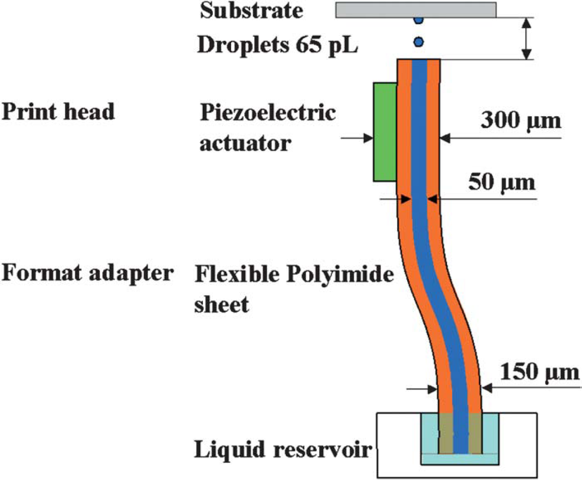
Schematic channel cross section of a I-dimensional dispenser array.
The dispensing mechanism relies on piezoelectric actuation. We use thin ceramic plate actuators made of lead zirconate titanate (PZT). The actuator squeezes the μ-channel and creates a stroke volume. The actuator has to be able to create the required stroke volume in some tens of microseconds in order to eject droplets at a sufficient speed. One part of the volume change is absorbed within the supply channel, and the other part is ejected through the nozzle. The relation between the two volume parts depends on the channel geometry, fluidic resistance, and on the physical properties of the testing liquid.
The device was fabricated with standard microelectro-mechanical systems (MEMS) technologies and microlithographies. 3 Starting material is commercially available heat-sealable polyimide sheets UPILEX® VT. Onto these 50-μm-thick polyimide sheets, thin film metal of aluminum (3000 A) is evaporated and patterned by lithography. The aluminum is etched by standard al-etch solution at a temperature of 42 °C. The metal layer is used as masking material for the reactive ion etching (RIE) of the polyimide. The μ-channels are anisotropically dry etched, which allows tight dimension control of the μ-channel sizes. The minimal structure size is about 30 μm. The etched polyimide sheet is then sealed with a blank polyimide sheet of the same material grade. The sealing is done by a thermal bonding process and is carried out with a mechanical press (Type 465: Erichsen; Hemer, Germany). The press is equipped with a bottom and top heating chuck. A bond pressure of 50 to 100 bars and a temperature of about 300 °C are applied for 30 to 60 min. On the prefabricated, sealed μ-channels, lithography is carried out and a gold electrode is evaporated. The electrodes are patterned by lift-off technology for not exposing the bonded polyimide to strong etch solutions. Next, the polyimide sheets are tailored by a deep UV-Excimer Laser. This process defines the outer surface of the nozzles and also defines the shape of the inlet side. Finally, piezoelectric actuators are attached with a nonconducting adhesive onto individual metal electrodes. The top electrode is contacted by a silver epoxy trace to the nearby thin film electrode. Then, the fabricated polyimide sheets are stacked together to form a 2-D printing array.
The inlet side of the dispenser has a fingered shape as shown in Figure 2. The inlet channel spacing of 4.5 mm fits to a 384-well plate. For aspirating, these fingers are immersed into the dispensing liquid positioned by mechanical alignment to the well plate. Next, the dispenser is clamped to the well plate. The dispenser to the well plate is sealed with a gasket, which allows pressurizing the wells and pushes the liquid into the μ-channels and up to the nozzle where it is stopped by surface tension. A back pressure of 10 mbar is applied to fill the μ-channel. A pressure of about 20 mbar would be required to push the liquid out of the nozzle and wet the nozzle's outer surface. The etched channels do not have any sharp edges or corners where air bubbles could be trapped during filling of the μ-channels. Bubble-free filling results in stable shooting. Once the filling of the channels is complete, the dispenser is ready to dispense. For convenience, the dispenser stays together with the well plate during the spotting; thus the dispenser shoots upward. The upward shooting has no influence on the drop formation because the kinetic energy is more significant than the force of gravity. The kinetic energy is about 50 to 100 times higher than gravity at a droplet speed of 2 m/s. The upward shooting avoids complex robotics for positioning and displacing, and the system becomes easy to handle and can be displaced manually. It is believed that the device could be used more than once. After dispensing, the dispenser is placed onto a well plate filled with a defined volume of cleaning solution. Applying a back pressure of 0.5 to 1 bar, the cleaning solution is flushed through the channels and out the nozzle, where the cleaning solution is collected by an absorbing tissue. The internal volume per channel of a full-size dispenser is only 2 μL, and a 384-well plate has a volume of 100 to 120 μL. After the cleaning solution is flushed through the channels, nitrogen from the pressure source dries the μ-channels. The cleaning procedure takes some time, but once the channels are dried, the device can be refilled from another well plate.
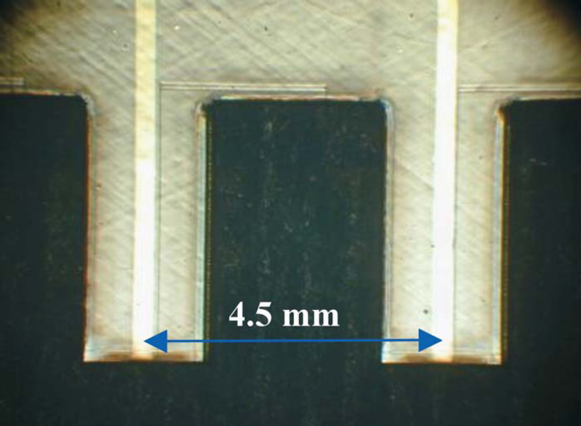
Fingered shape of the inlet side of the dispenser at a spacing of 4.5 mm. The polyimide outer shape was cut with an Excimer Laser at a wavelength of 193 nm.
The format transfer from 4.5 mm to 500 μm is done in both x- and y-directions. In the x- direction, the channels are etched into a polyimide sheet in such a manner that all channels come together to form a 1-D nozzle array at a spacing of 500 μm as shown in Figure 3. In the y-direction, the polyimide sheets are assembled in a modular way by using the flexibility of the thin sheets. A bonded sheet is 150 μm thick and reaches a total thickness of 300 μm with the piezoelectric actuators. Single sheets are stacked together to form a 2-D printing array. Spacers have been used to respect a spacing of 500 μm. A top view of an assembled 2 × 3 nozzle array is shown in Figure 4. The smaller picture in Figure 4 shows a close-up of a single nozzle. The sidewall angle of the nozzle is defined by the anisotropical plasma etching process and has a slightly trapezoidal shape of about 50 μm. The trapezoidal nozzle shape has not shown any negative aspects in the experimental phase.
Front view of an assembled l-D dispenser array. The channels come together to form a nozzle array at a spacing of 500 μm. On the right and left of the channels, thin-film electrodes connect the piezoelectric actuators. At the bottom is a homemade well plate with the same spacing as a 384 plate. The bores on the side are used to pressurize the wells for filling the dispenser.
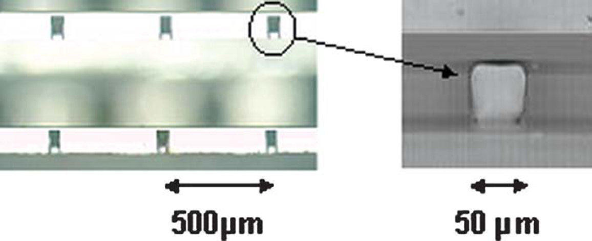
An assembled 2 × 3 nozzle array in microarray format is shown on the left (top view). On the right-hand side is a close-up of a single nozzle. The nozzle has a slightly trapezoidal shape with a dimension of (60/40) × 50 μm2.
Drop formation is analyzed by video observation under stroboscope illumination. The test liquid is degassed water. The dispenser assembled to the well plate is shooting upward as shown in Figures 6 and 7. A microscope with a variable zoom is installed horizontally at the height of the nozzle to observe the drop formation. Opposite of the microscope, a red light-emitting diode (LED) for the stroboscopic illumination is positioned. The driving signal for the LED is a square wave with an amplitude of 5 volts and pulse length of 2 μs. During the 2- μs pulse, length the droplet only moves about 4 μm for an ejection speed of 2 m/s, which still results in a fairly sharp image. The LED driving signal is synchronized with the driving signal of the actuator with a variable delay time from zero to 500 μs. Installed on top of the microscope is a black-and-white charge-coupled device (CCD) camera with video output (CCD-IRIS: Hi Resolution; Sony, Japan). The video is recorded onto a Mini DV cassette for further treatment. The dispenser is able to dispense up to 5 kHz, but the dispensing frequency has been set to 500 Hz for video recording.
Results
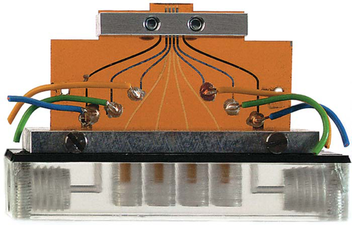
A prototype of two assembled 1-dimensional printing arrays was built to form a 2-dimensional array as shown in Figure 5. The bottom plate represents the well plate. The bore in the middle part is used to pressurize the reservoirs for filling. On the flexible polyimide sheets, there are integrated thin film electrodes to connect the piezoelectric actuators. Electric wires are simply glued onto the lower end of electrodes to connect an external driving circuit. The clamps fixing the dispenser to the well plate have been omitted for better illustration.
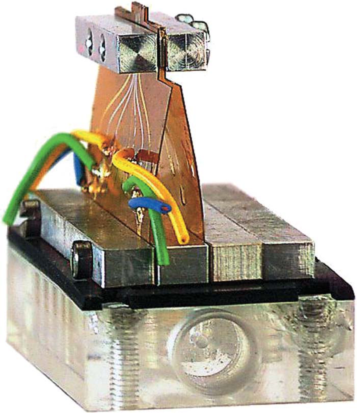
Side view of an assembled 2-D dispenser array. The flexibility of the polyimide sheets allows stacking of single sheets to form any desired format up to 24 × 16.
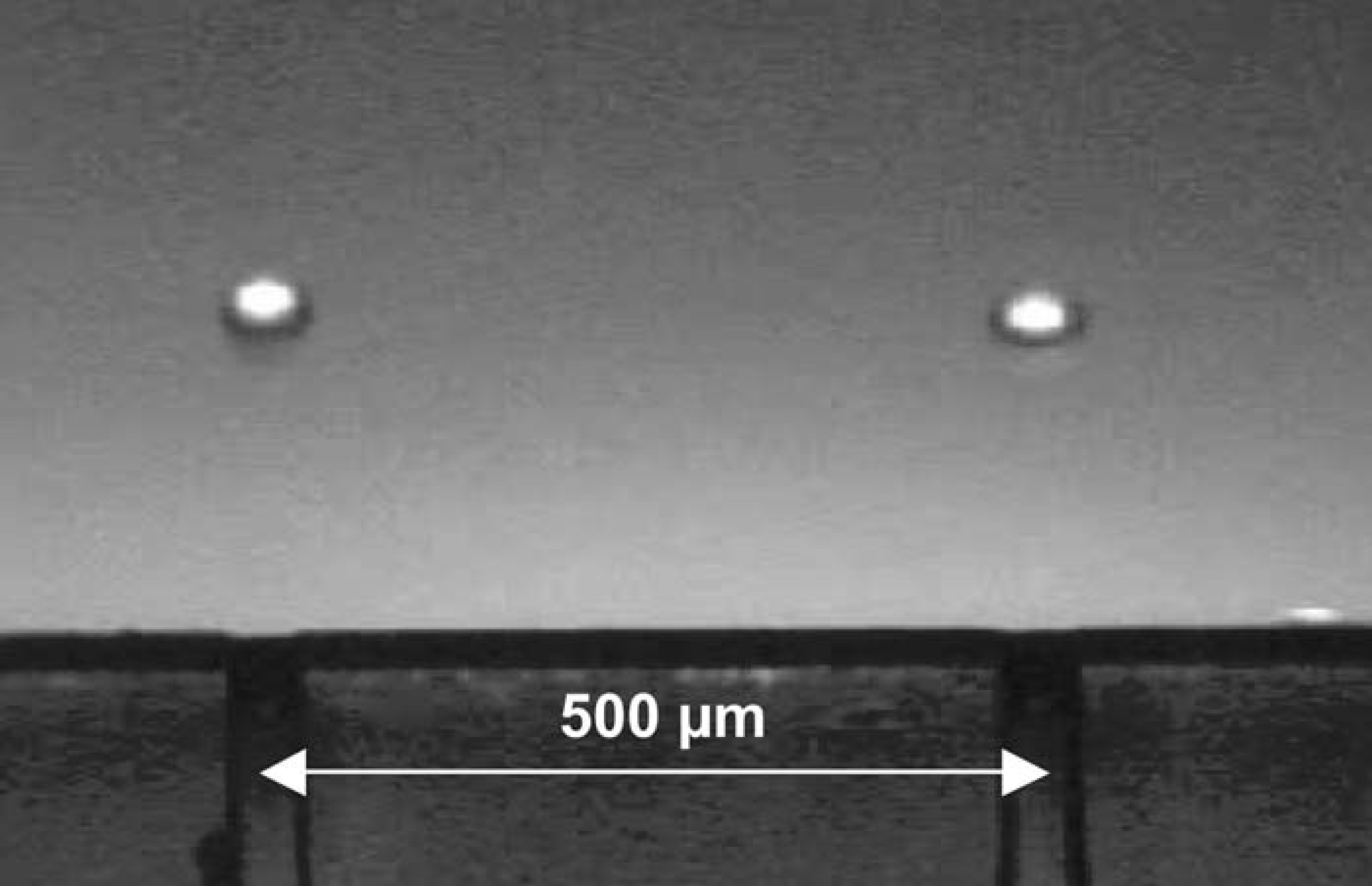
Parallel dispensing of 65 pL droplets at a spacing of 500 μm. This photo was taken with a stroboscopic illumination at a delay time of 150 μs. The dispensing frequency was 500 Hz. A good directionality and satellite-free droplets are achieved within this prototype.
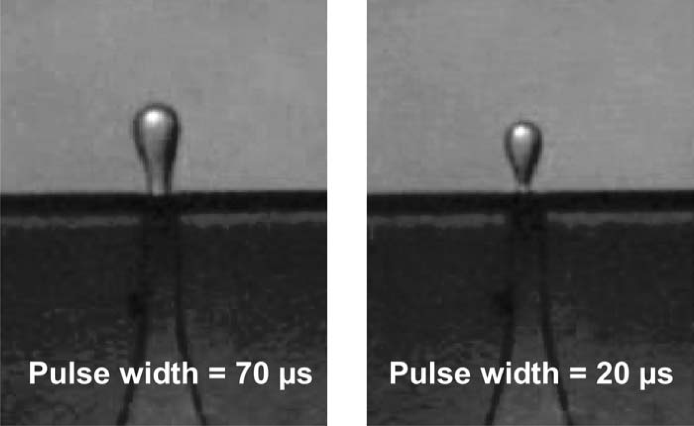
Drop formation for different pulse width. A controlled volume change can be seen between the left and right image. These pictures are taken under stroboscopic illumination at a delay time of 60 μs.
Figure 6 presents a close-up of two channels during dispensing at 500 Hz and at a delay time of 150 μs. The image corresponds to a superposition of some tens of droplets. No wetting of the nozzle outer surface is observed. Ink-jet-based dispensers often show small secondary droplets called satellite droplets next to the main droplets. 2 Satellite droplets are undesirable because of cross contamination between spotting sides. Satellite droplets are avoided by using polyimide substrates and by optimizing the driving signal. Polyimide substrate tends to damp any secondary waves, which might provoke satellite droplets. No satellite droplets were observed for a rise and fall time of 5 μs for the driving signal of the piezoelectric actuator. 4 The sharpness of the image is a good indication of stable droplet shooting as demonstrated in Figure 6. The droplet ejection speed is about 2 m/s. At this speed, no splashing occurs when the droplet arrives on the surface. A slight speed difference between the channels was observed, but it does not influence the spotting quality. The droplet volume is calculated by measuring the droplet diameter with a microscope. This method is a rough estimation for the first prototype. Droplets have a nominal diameter of 50 μm and the dispensed volume is then about 65 pL ± 15%.
An important parameter for multichannel dispensing in microarray format is the directionality of the droplets. A good directionality avoids cross contamination between spotting sides. The cutting quality and the non-wetting properties of the nozzle outer surface appear to be key factors. High cutting quality is reached by photoablation with a deep UV-Laser Excimer at a wavelength of 193 nm. A hydrophobic surface quality is given without a surface treatment by the property of polyimide. After cutting, no wetting on the nozzle's outer surface is observed. Because both factors are fulfilled, the droplet deviation is smaller than ±5° and results in maximum misplacement of 44 μm for a substrate distance of 500 μm.
The stability of multichannel parallel dispensing was also investigated. A square-shaped pulse of about 150 volts was applied to the piezoelectric actuators to create different pulse widths. For pulse widths ranging from 20 to 70 μs, droplets are ejected. However, the stroboscope image indicates a droplet volume change in function of the pulse width. This effect is demonstrated in Figure 7. At a larger pulse width, the actuator creates a larger stroke volume, which explains the volume change. The wide range of the pulse width allows driving all channels at one common driving signal and makes it nonsensitive to small signal change. This is an important advantage for a full-size dispenser (e.g., 24 × 16) where only one power supply may be used.
After analyzing the droplet formation, parallel spotting onto a glass slide was explored. The dispenser is fixed to the well plate and stands on a table. On the top of the nozzle array a glass slide is placed at a distance of about 0.5 mm. A microscope with a video camera is installed above the glass slide. The droplets are observed through the glass slide during dispensing. In Figure 8, droplets are dispensed in parallel at 1 Hz. All three channels have the same electrical driving signal. By adding another sheet to the 1-dimensional dispenser array, a 2-dimensional microarray is formed. The parallel spotting of 2 × 3 array is shown in the smaller portion of Figure 8. A slight difference in the dispensed volume between the two sheets is observed because of different nozzle sizes from the etch time in the plasma reactor. When the dry-etching process is optimized, this aspect is reduced. All channels have the same driving signal and are connected to a single power supply. Parallel spotting in a microarray format significantly increases the throughput, which is required for HTS applications.
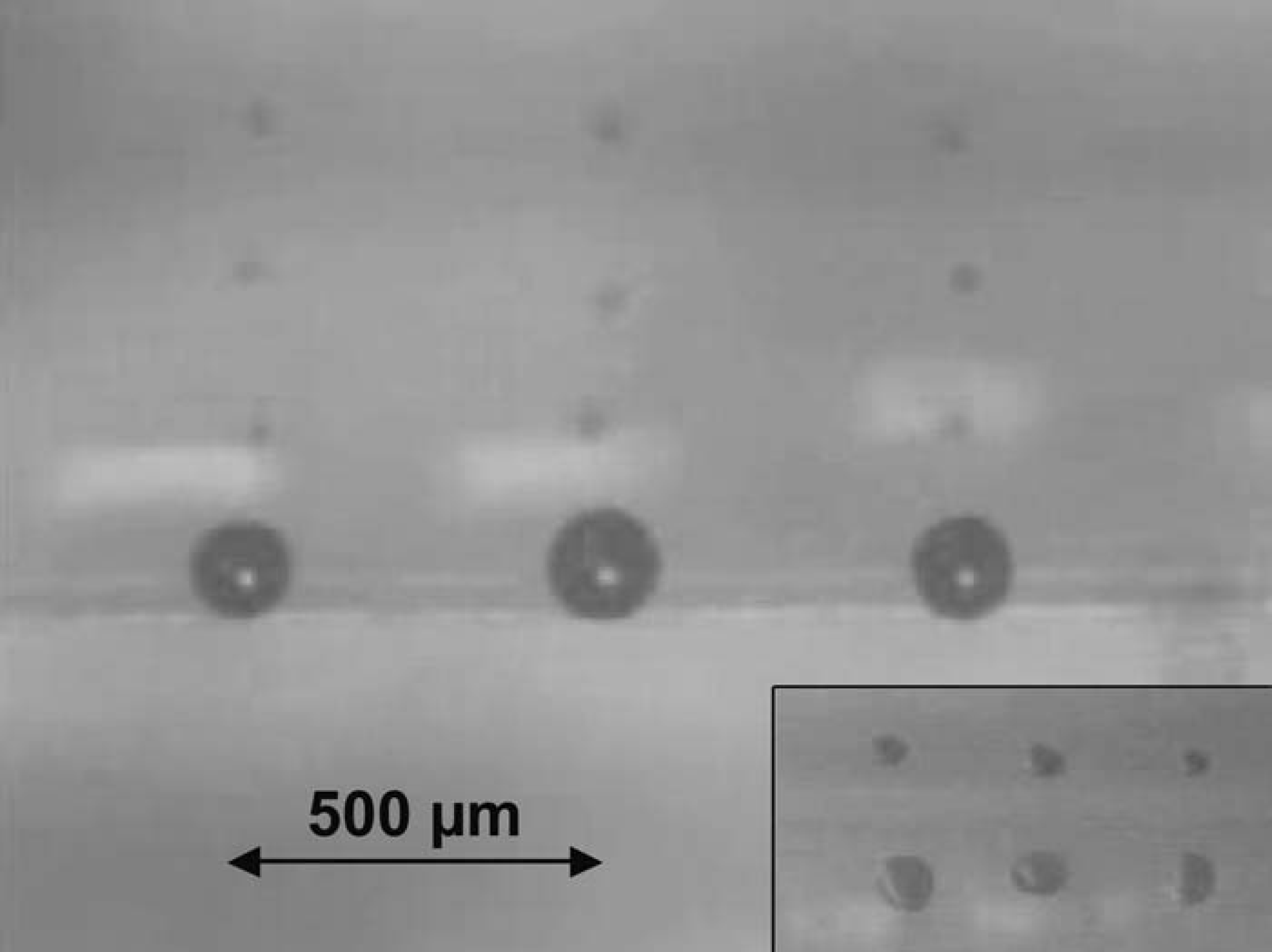
Parallel spotting onto a glass slide. The larger image shows a close-up of three nozzles at printing. The I-D dispenser is manually displaced at 200 μm. The smaller image presents a close-up of 2-D parallel spotting of 2 × 3 array at a spacing of 500 μm in x- and y-direction (bottom right).
Outlook
There are future plans to fabricate a 24-channel, 1-dimensional array dispenser. The polyimide sheets will then be 6 inches square. After successfully dispensing with the 24-channel dispenser, a 2-dimensional array will be built and characterized, and then a 24 × 16 array will be assembled and tested.
Conclusion
A multichannel parallel dispenser for a 2-dimensional micro-array format has been built and characterized. The flexibility of the polyimide substrate allows forming arrays by stacking of single sheets. The dispenser is scalable to any desired format up to an array of 24 × 16. Drop formation is analyzed with stroboscope illumination for different driving signals. A good directionality of less than 5° deviation of the droplets is reached without satellite droplets. The continuous filling from a 384-well plate makes the device easy to handle and minimizes the waste of samples and reagents. After filling, thousands of droplets of 65 pL can be dispensed in parallel onto different microarrays.
Acknowledgments
The authors would like to thank the following people and institutions for their cooperation and assistance: Prof. Herbert Keppner (HESSO) and Daniel Gigon (HESSO) for dry etching of polyimide sheets; technicians Nicole Hegelbach, Gianni Mondin, Sylviane Pochon, and Sylvain Jeanneret at IMT, University of Neuchätel and at HESSO; and the University of Applied Science, Le Locle. Their contributions are gratefully acknowledged. This work has been supported by the Swiss Commission for Technology and Innovation CTI.