
Abstract
This article addresses the problem of trajectory tracking in crops by a weed sprayer mobile robot (WSMR). This problem arises because to fumigate, the robot must follow a predefined path and avoid any obstacles it may encounter.
To achieve both trajectory tracking and obstacle avoidance, a control scheme based on different behaviours is proposed, which consists essentially of an adaptive controller with a reference model for trajectory tracking and a fuzzy reactive for obstacle avoidance. Each of these controllers is executed according to the selection of the fuzzy behaviour controller, which uses information delivered by anti-collision sensors located on the robot.
As a result of the implementation of this behaviour-based architecture and by means of computer simulations and experimental laboratory tests, the WSMR demonstrates the capability of autonomously following a desired trajectory between the rows of a crop in the presence of obstacles. The results are evaluated by taking into account trajectory tracking curves and the operating requirements of each controller, as well as the application of different errors indices for quantitatively evaluating the proposed control scheme.
1. Introduction
Mobile robotics is a novel research field that encompasses many branches of science and engineering such as mechanical, electric, electronic and automation engineering, among others.
In contrast with manipulator robots, which represent most of the industrial sector and are capable of carrying out repetitive tasks with very high precision, mobile robots can move across the real world to perform a range of different tasks, which renders them much more versatile.
However, this versatility poses a challenge, since displacement through stochastic and in some cases hostile environments represents one of the main barriers that these robots must overcome. Therefore, during the design process, it becomes necessary to define the system of locomotion, perception and manipulation that the mobile robot will use, based on the displacement needs, characteristics of the land, and the work environment.
The position control and trajectory tracking of mobile robots with non-holonomic constraints has been a problem of great interest to many researchers and the literature provides various methods for dealing with it [1–17]. Nevertheless, in an agricultural context, some previous approaches have attempted to solve these issues [11–12,15–16], but none have truly succeeded. This is largely due to the unknown and stochastic agricultural environments mobile robots have to work in, requiring them to have high levels of adaptation and efficiency. This paper aims to overcome the shortcomings mobile robots have by providing a new alternative based on behaviour-based architecture.
Robot control based on behaviour is more than an extension of reactive control. Behaviour-based control, which can be implemented in many ways, is not only limited to sensing the setting and carrying out actions. It consists of a central control module which, depending on the variables within the surroundings, coordinates different simple behaviours to control the mobile robot. These behaviours are not executed in a serial manner, but in a coordinated manner, depending on established priority and hierarchy.
Several methods for evading obstacles, together with subsequent trajectories [2,4,9,11,12,14,17] have been proposed in the literature. However, the main goal of the current work is to design and implement a robust and easy-to-implement path-tracking controller that is flexible enough to work in unknown and changing environments. In addition, this controller will be the principal component of a hybrid control system that will employ – in a secondary way – a reactive or behaviour-based control for a mobile robot performing crop-harvesting tasks.
This article proposes architecture based on fuzzy behaviours, the control scheme of which is designed to allow a mobile robot to move through crop rows, avoiding obstacles that may appear in its way. That architecture uses a diffuse controller to select the different types of behaviour that the robot should exhibit according to land conditions by defining whether the robot should avoid the obstacles, or whether it should follow the desired trajectory.
First, tests are conducted with and without obstacles. Subsequently, the first case is taken as a reference, allowing for the comparison of results pertaining to the robot's performance with results obtained in the second test by considering different performance criteria. The first and second tests are carried out using Simulink® software in simulation environments and in a laboratory scenario, respectively.
The results are revised and discussed with the purpose of determining whether the developed control scheme allows the robot to fulfil the requirements for displacement through crops for which it was designed. Finally, future work is described.
2. Modelling of a Differential Mobile Robot
In order to carry out the evaluation of the different controllers and their responses to tracking a reference path, a differential kinematic model for the WSMR was considered, as shown schematically in Figure 1. Additionally, this robot can be represented by:

where x and y are the coordinates of the centre C and θ is the orientation angle of the mobile robot, taken counter clockwise from the X-axis. The angle θ is restricted within the
By using the kinematic relation (2), it is possible to determine the position and orientation of the mobile robot in the global reference system.

where
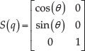
The matrix S(q) is given by:
The model of the WSMR has three output variables that represent the Cartesian position and orientation of the device with respect to a reference system, as well as two inputs corresponding to the linear and angular speeds of the mobile robot.
However, these inputs can be transformed into the angular speeds of their wheels by means of relation (4).
To achieve path-tracking control, it becomes necessary to act on the wheels of the mobile robot. Then, the relation between the linear velocity and the wheel is given by:

where

Representation of the mobile robot considering speeds in local global reference systems
In order to move the robot's wheel axles, direct current motors were used. Consequently, alongside the robot's kinematic model, the dynamic model for the actuators of each wheel –a simplified dynamic model that provides the wheels with movement – was considered. This corresponds to a transference function of equation (5), which relates the voltage with the speed or position of the axis:
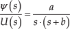
where ψ is the position of the motor axis, U is the motor input voltage and
Although some authors consider the forces and speeds at the wheels, the torques of the motors, inertia and friction in the dynamic part of the model [1, 3], these aspects are not included in this article. This is because these robots do not possess a configuration that justifies including the aspects aforementioned, as is the case for skid-steering mobile robots [13], in which the dynamics directly affect the position control as a result of the traction implemented in them.
Moreover, representation of the inertia and friction matrices of the motor implies the use of unknown motor parameters, which are uncertain and can therefore be discarded. Hence, the representation of dynamics considering only the motor is sufficient for the complete representation of the robot. Moreover, simulation without dynamics is sufficient for performing tests and simulations with the mobile robot [2].
In this type of robot, the motor axle moves in the same direction of the wheels; thus, the forces that can disturb or affect the model are considered negligible and the controllers that act on the wheels mitigate any possible negative effects. The inclusion of the sensors is considered more relevant to the simulations, since they represent the perception of the mobile and adverse effects that the sensors might produce in the trajectory control loop.
3. Implemented Behaviour-based Scheme
This works proposes a hierarchical hybrid behaviour-based control scheme in which global coordination is performed by a fuzzy controller. The behaviour-based approach is a methodology for the design of a robot and controller architectures that provide robots with intelligent behaviour from a biologically inspired philosophy, based on parallel and decentralized architectures. Thus, the robot has sufficient flexibility to work in unknown and changing surroundings. Furthermore, the adaptive controller allows the robot to have a degree of adaptation to the environment. This is important in the context of mobile robots, since they need to be capable of moving autonomously along crops and considering the stochastic conditions presented in orchards and crops.
The implementation of these types of controllers is a key factor for the robot to be able to execute other field tasks efficiently and move around, and does not demand a high level of processing.
The control scheme has five different stable states arranged hierarchically. These commute depending on the measurements delivered by the different anti-collision sensors mounted on the mobile robot, which react to a series of previously defined behaviours. This study's scheme differs from others presented in the literature, as it uses an adaptive controller that has already been tested [18] and a reactive scheme in which each different behaviour is activated by switching between different states.
These types of hybrid control architectures, based on the transition between different operating modes, allow for evading obstacles and following trajectories through simple behaviours that act on low-level controllers in order to obtain the expected control results. The proposed control scheme is shown in Figure 2.

Hierarchical control scheme for navigation and path tracking in crops
Commutation between the different high-level behaviours is carried out by a fuzzy selection system which, using the measurement made by the anti-collision sensors, defines three behaviour zones for the robot, as shown in Figure 3.

Distribution of mobile robot collision avoidance sensors
In the behaviour selection system (BSS), different membership functions are created for each sensor and these measurements are conjugated by means of fuzzy rules to define the different selection behaviours that allow the system as a whole to continuously switch between a reactive mode and trajectory-tracking mode, thereby constituting a fuzzy state selector.
The inputs of the fuzzy selector correspond to the anti-collision sensors, each of which is represented by three membership functions: an obstacle at a far distance (F), at a medium distance (C) and at a close distance from the robot (N), as seen in Figure 4. The range used corresponds to the maximum distance that a commercial ultrasonic sensor can measure.
The output of the fuzzy selector corresponds to the different behaviours expected from the WSMR, according to the measurements delivered by the sensors, which are indicated in Figure 2. Each sensor is represented by five membership functions, namely obstacle on the right (OR), obstacle on front right (OFR), path tracking (PTRACK), obstacle on front left (OFL) and obstacle on the left (OL), as shown in Figure 5.
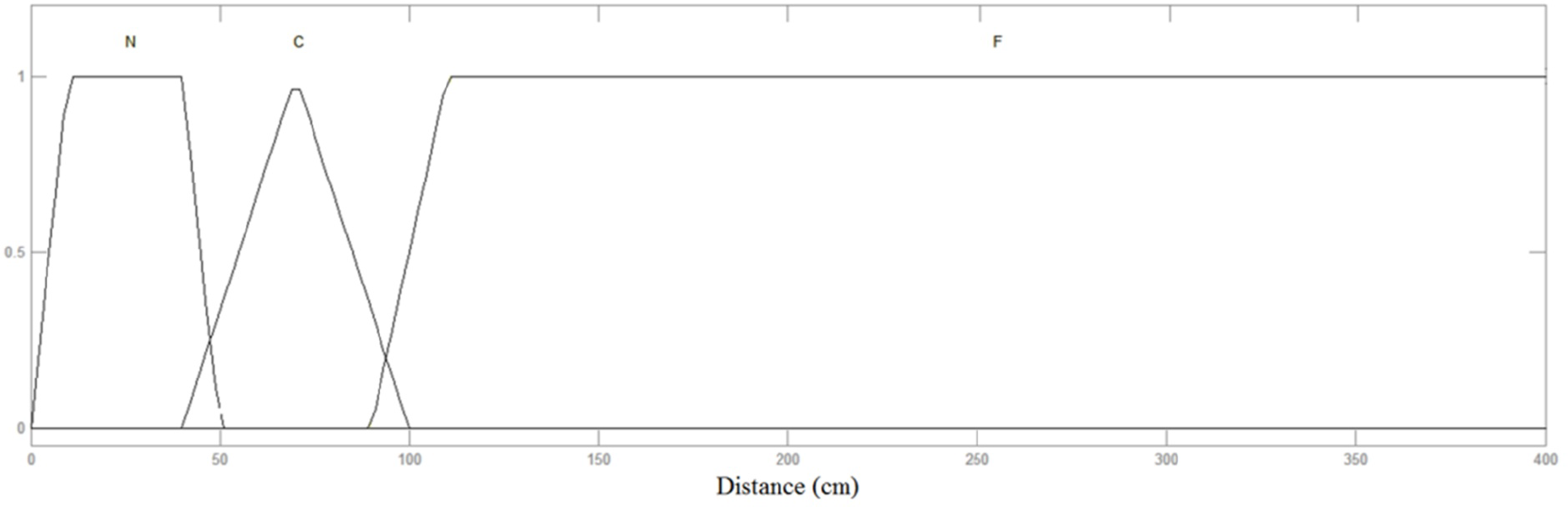
Membership functions for the distance to the obstacle
Each of these inputs and outputs are coupled in a Mamdani-type fuzzy controller from a set of fuzzy rules. The created premises do not consider all the variables or functions, since among all of them, there is not necessarily a relation for determining the behaviours expected of the robot. These rules are simple and represent the expected behaviour of a biological being. The WSMR's reaction can be defined as in Braitenberg's studies on behaviour and cognition, i.e., as a phobia of obstacles, since each time an obstacle appears, the robot escapes it by taking the opposite direction.
The set of rules is shown in Figure 6.

Membership functions for behaviours

Selection rules for fuzzy behaviours
3.1. Path tracking
A MRAC (model reference adaptive) controller similar to that shown in Figure 7 was used in the general architecture, considering as inputs the displacement error and the distance from the target point. The controller outputs correspond to the angular speeds of each wheel, which represent the speed control references of the motor in the inner loop. However, the references for this controller correspond to the value zero “0”, since the objective of the control is the distance and deviation differences between the target point and the mobile robot to become zero.
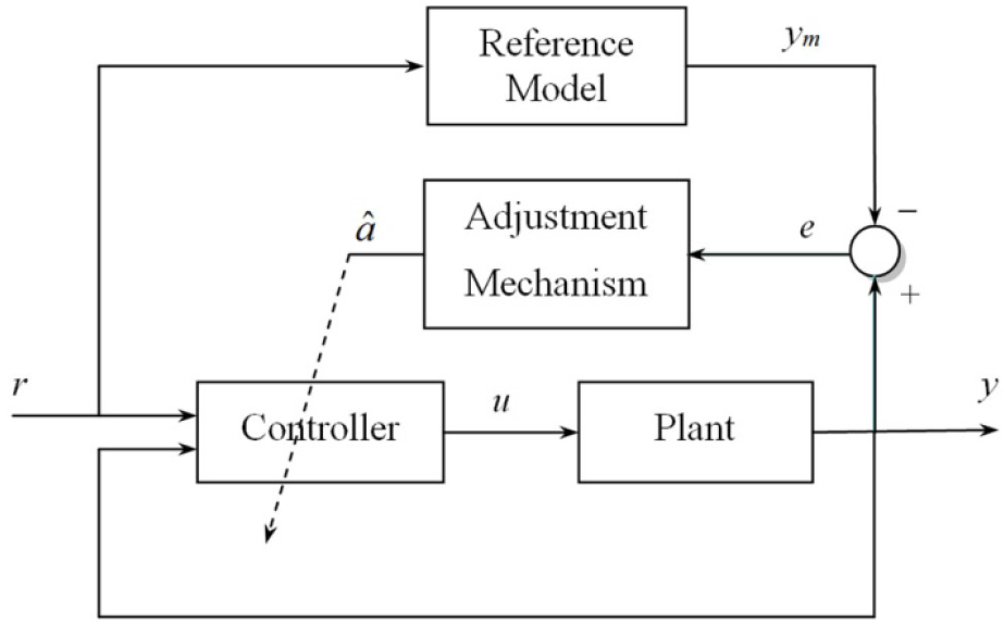
Scheme used for the MRAC controller
For the implementation of the MRAC, a damped second order was considered as reference model, which was represented by means of its transfer equation.
In this way, the kinematic model for the mobile robot with MRAC control is transformed into:

where a0 and a1 represent the adaptive parameters of the controller, which were calculated from the following adaptation law:


where controller parameters
Subsequently, the MRAC outputs are converted into reference signals for both wheels of the mobile robot, making it possible to achieve the desired path tracking when the internal control loop is executed.
This MRAC is used as it exhibits several advantages compared to other similar controls [18]. Despite the MRAC being equally complex in its implementation in a real system and having computational requirements similar to those presented in [18], it has better transient response, which depends on the reference model being used. Furthermore, it only requires adjustment of one adaptation or learning parameter to achieve the desired reference. This allows for executing the selection of controller parameters by running different tests with trajectories similar to that proposed in Figure 7, as well as selecting the parameters that show the best performance in these tests.
3.2. Obstacle avoidance
To implement the evasion of obstacles in the mobile robot, a reactive control scheme based on well-known fuzzy logic is used, which —from the different behaviours defined in the scheme of Figure 2 and the sensors shown in Figure 3 — allows for the WSMR to avoid obstacles on its trajectory. The use of collision sensors for evading obstacles is one of the most widely used methods for achieving reactive behaviours in mobile robots [6, 14, 17].
The reactive fuzzy controller is based on the information obtained from the fuzzy scheme of BSS defined above, i.e., control decisions are made taking into account only information about the sector in which the obstacle is placed and not the sensors’ measurements. Therefore, the input of the reactive fuzzy controller corresponds to the membership functions of Figure 4 – defined above – while the outputs are given by the functions in Figure 8, which determine the speed of each of the robot's wheels. The functions correspond to zero speed (ZE), low speed (PL), medium speed (PM) and high speed (PB). The range used for speed was defined according to the mean of the speeds obtained in tests using the controlled robot model.

Membership functions for the wheel speed of the mobile robot
As in the fuzzy selector, each of these inputs and outputs is coupled in a Mamdani-type fuzzy controller from a set of fuzzy rules, which allow the output to act in the wheel's angular velocity, depending on the input data. The set of rules is given in Figure 9.
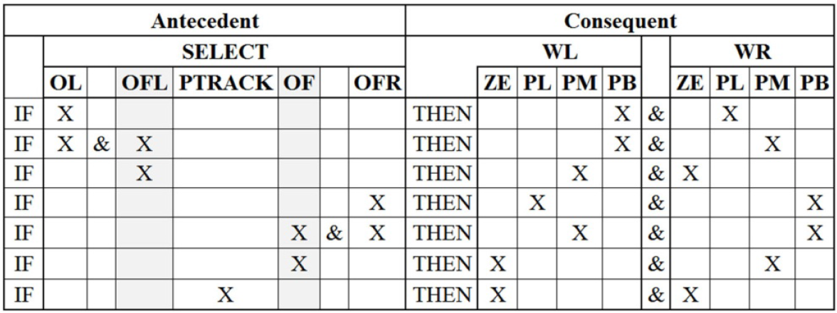
Rules for reactive obstacle avoidance
4. Computer Simulations, Prototype Test and Synthesis of Results
The control scheme shown in Figure 2 was implemented in Simulink® and initiated with blocks and functions. In this simulation setting, commutation tests were run for the different behaviours expected of the mobile robot, according to the different transitions given by the robot's collision sensors and within the defined stability ranges.
The sampling time was set at 0.02 s, with random Gaussian errors to represent measurement imprecisions on the part of the sensors, keeping in mind that the maximum is given by the values indicated in the data sheets of commercial devices. The real admissible voltage limits for the motors of each wheel were also considered.
To obtain the desired speed in the actuators (inner loop), a classical PID controller was used; MRAC was employed for the position control loop (outer loop).
The WSMR under the behaviour-based scheme is subjected to a number of different test trajectories, the most important being the one presented in this study, which emulates the real displacement in a crop, where the mobile moves through different rows to fumigate weeds. The reference trajectory used is shown in Figure 10; tests were conducted on this trajectory with and without the presence of obstacles.

Reference trajectory for the mobile robot (Image: Google Earth, 2013)
The results for an ideal situation for following trajectories without the presence of obstacles, in which only the MRAC control is used and where there is no commutation between the control modes, is shown in Figure 11.
Since farms do not constitute a deterministic environment such as greenhouses, it is highly likely that the robot will find obstacles on the desired path and will thus need to avoid a collision with these in order to continue working.
Figure 12 and Figure 13 show the results for following the trajectories in the presence of obstacles for two different cases.
Figure 12 shows the result of subjecting the robot to an extreme condition (test 1) on the edge of the commutation stability of control modes, with obstacles moving toward the robot, forcing the mobile robot to react drastically to avoid them.
In contrast with the previous case, Figure 13 shows the result of subjecting the mobile robot to static obstacles (test 2), which it easily overcame.

Path tracking without obstacles. The desired path is shown in black; the position and orientation of the mobile robot are represented by grey triangles.
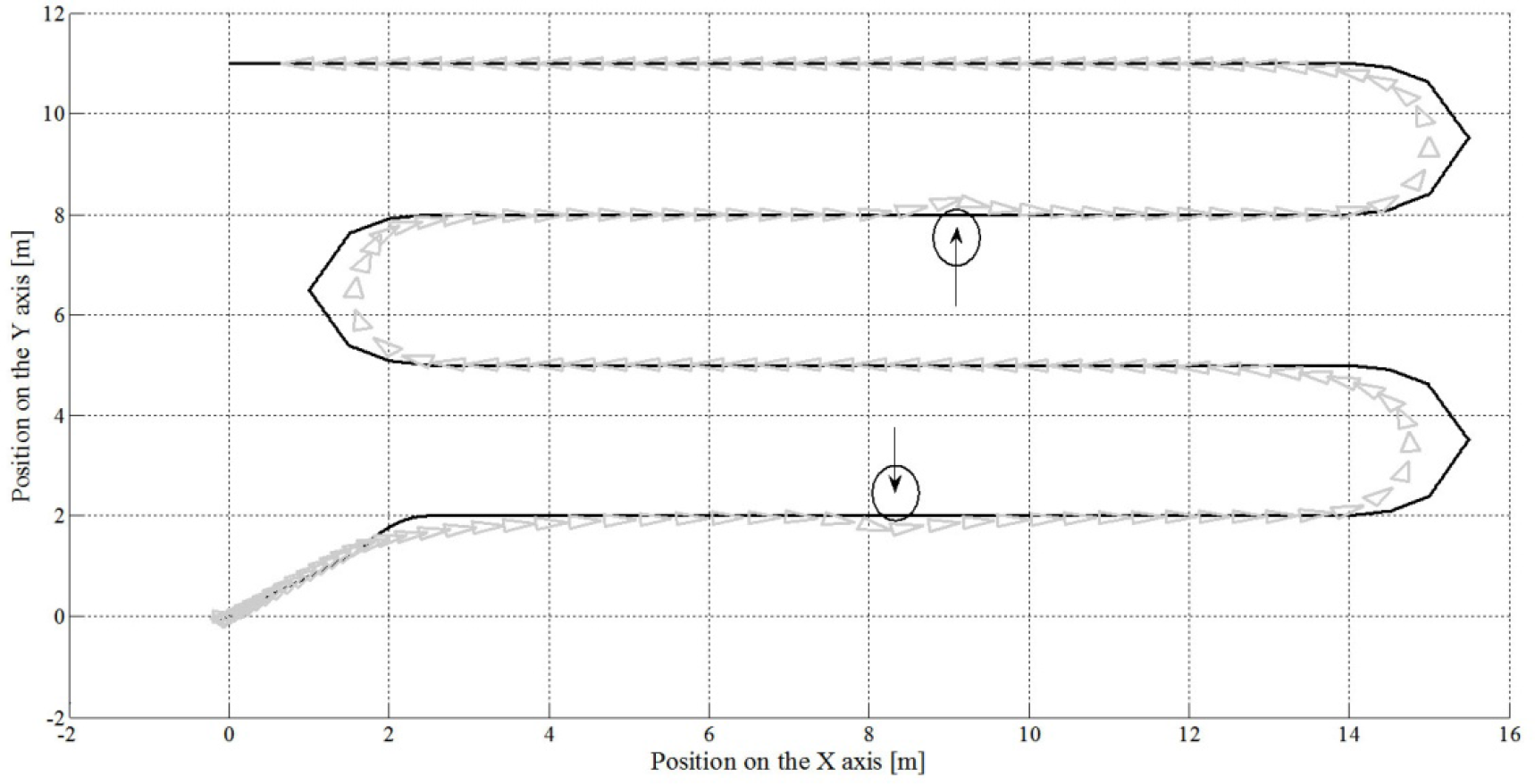
Path tracking with obstacles (test 1). The desired path is shown in black; the position and orientation of the mobile robot are represented by grey triangles.

Path tracking with obstacles (test 2). The desired path is shown in black; the position and orientation of the mobile robot are represented by grey triangles.
To evaluate the tracking of trajectories quantitatively, different error indices are used, allowing for a comparison of the real trajectory followed by the mobile robot with the reference trajectory. The three indices used are described in detail in [18].
Each of these indices permits the evaluation of the robot's behaviour in a different way with respect to the correct tracking of the reference trajectory on each Cartesian axis. However, the values shown in Table 2 correspond to the average value between the X axis and the Y axis.
The use of three different indices allows – when conducting a joint comparison – for the elimination of the statistical bias and local errors that can lead to incorrect conclusions, which will not be the case when only one index is used.
Considering that the results shown by the error indices were within the expected range and taking the ideal case without obstacles as reference, it can be seen that the trajectory tracking in the case with obstacles is acceptable.
Test error indices

However, to completely evaluate the performance of the WSMR and the proposed BSS, a laboratory test was performed, as shown in Figure 14. As indicated in the image, for the WSMR to avoid an obstacle in the left or right side of crop rows when following the desired path, it is necessary that the BSS shifts to the reactive controller as the obstacle is being avoided.
In Figure 14, the moment when the WSMR shifts to the reactive control can be observed. At this stage, the WSMR follows the shape of the obstacle and finally, returns to the desired path when the measurements of the anti-collision sensor indicate to the BSS that the obstacle has been overtaken.

Laboratory test with WSMR
5. Conclusions and Future Development
The simulations and laboratory tests presented in this paper are considered an encouraging first approach that suggests a behaviour-based control scheme is sufficient for the proposed control objective, and that it provides the majority of the tools the mobile robot needs to perform autonomously in crop environments.
By means of a simple hierarchical control scheme that does not imply a high cost in terms of hardware requirements, it is also possible for the robot to perform, in addition to autonomous navigation, other tasks on the farms.
A stability analysis that considers the proposed BSS as a hybrid control system composed of transitions and stable states is without doubt part of future work. Additionally, not only is it important to verify the stability of individual states, but also stability in transitions. Nevertheless, the study of instability is discarded for now, since the control scheme by itself assures the required stability at this stage, as demonstrated by the results obtained through BSS during testing.
Footnotes
6. Acknowledgements
This work was supported by Proyectos Basales and the Vicerrectoría de Investigación, Desarrollo e Innovación of the Universidad de Santiago de Chile, Chile.