
Abstract
This paper presents a motion control for an autonomous robot navigation using fuzzy logic motion control and stereo vision based path-planning module. This requires the capability to maneuver in a complex unknown environment. The mobile robot uses intuitive fuzzy rules and is expected to reach a specific target or follow a prespecified trajectory while moving among unforeseen obstacles. The robot's mission depends on the choice of the task. In this paper, behavioral-based control architecture is adopted, and each local navigational task is analyzed in terms of primitive behaviors. Our approach is systematic and original in the sense that some of the fuzzy rules are not triggered in face of critical situations for which the stereo vision camera can intervene to unblock the mobile robot.
1. Introduction
Mobile robot application areas increase every day. They used to be found in working stations in factories. The growing interest in service robotics extended their use to include many applications. In these applications the environment is stationary and the mobile robot can be assigned a predetermined path to act on a desired task. However in many applications, the robot has to execute its task in an unstructured dynamic and complex environment [1]. By unstructured environment, we mean no prior knowledge of the space the robot is evolving and no prior knowledge of the disposition of the static objects considered as obstacles. On the other hand, dynamic environment is defined as an environment with changing surroundings such as moving objects. To achieve these requirements, the robot must sense the environment and respond to events in order to plan its path to target. This type of navigation is called reactive navigation.
Many approaches for obstacle avoidance in local navigation can be found in the literature, they include: Wall following [2, 3], Edge detection [4], Potential field [5], Vector field histogram [6], Virtual force field [7, 8], Certainty grid [9] and Behavioral based approach [10]. Research in this area is still emerging, since there is no unified approach which integrates all the facilities and come up with an optimized solution. Accordingly, several important control strategies for mobile robot navigation based on fuzzy logic control are being developed adding to an already existing works (e.g, [11, 12]). This present interest is largely due to the successful applications of fuzzy logic control to a variety of industrial systems. Its main components are an inference engine and a set of linguistic If-Then rules that encode the behavior of the mobile robot. However, the main difficulty in designing a fuzzy logic controller remains the efficient way of formulating the fuzzy If-Then rules. Nevertheless, to achieve the objective of target tracking and obstacle avoidance, fuzzy sets and rule base are used to model the environment and determine the behavior of the robot when facing novel situations. Recently, mobile robot controllers based on Spiking Neural Networks (SNNs) which have been inspired from biological neural network were successfully implemented for clockwise and counter-clockwise wall following [13, 14].
This paper presents a solution to mobile robot navigation in an unknown environment. The mobile robot is equipped with three types of sensors that provide useful information for the system good behavior. Each behavior is designed to coordinate and compete with other behaviors to the success of the mobile robot mission. The ultra sonic sensors (US sensors) provide range reading, thus determining the distances between the robot and the obstacles. The US sensors can also be used to provide information related to wall following. The other type of sensors concern a vision system to assist the mobile robot in making the right decision in case of conflict, such as local minima, turn left or right, choosing a shortest path, etc. The inputs characterizing information on the environment are fuzzified and presented to the inference engine for generating control outputs.
In this paper, we treat the problem of robot navigation with obstacle avoidance behaviors in a hierarchical way. We decompose the whole task into different behaviors and execute each one independently or in conjunction with the others. Each behavior is composed of a set of fuzzy rule statements. This is done in the framework of fuzzy logic inspired by the human capacity to reason with perception based information. Our approach is systematic and original in the sense that some of the rules are not triggered in face of critical situations. The stereo vision camera can substitute the fuzzy logic motion controller to unblock the mobile robot and providing the shortest free path.
2. Behavioral-based fuzzy control architecture
2.1 Fuzzy control
Fuzzy logic was first introduced in 1965 by L.A. Zadeh of the University of California at Berkley [15]. Fuzzy control is then derived to deal with many applications such as engineering, science and data analysis. The idea behind using fuzzy reasoning is its ability to deal with approximate, ambiguous and uncertain data. There are mainly three steps for designing a fuzzy controller: Fuzzification, Inference engine and Defuzzification.
a) Fuzzification
Fuzzification is a mapping of a real-valued variable x to a fuzzy set. Membership functions constituting the fuzzy set may be singleton, triangular, Gaussian or trapezoidal. The real valued variable x can belong to one or more membership functions. All the values of all variables representing the input and the output of the system are fuzzified.
b) Inference engine
Once the input and output variables are defined, fuzzy inference engine is used to design the rule-base composed of IF-THEN rules to convert the inputs into output membership functions. The more variables we use, the more rules result. However, it is not necessary to translate all the rules, sometimes they can be redundant. The degrees of membership of the inputs are combined to obtain the membership degree of the output variable.
c) Defuzzification
The last step for designing a fuzzy controller is to convert the fuzzy output variables into a real valued variable, this is called defuzzyfication. Once defuzzyfied, the real output variable will be the actual input for the process. Many methods exist, permitting the transformation of the fuzzy output into a real valued. More details regarding the fundamentals of fuzzy control and design can be found in many textbooks such as Wang [16], Passino and Yurkovich[17].
2.2 Behavior-based design
The idea is to decompose the whole complex behavior into different simple behavior modules in a subsumption architecture [18]. Each behavior is executed independently or in conjunction with the others, and is formulated as a set of fuzzy rule statements. Behaviors that are usually needed for mobile robot tasks include (Figure 1):
Path following and goal reaching Obstacle avoidance Wall following Emergency
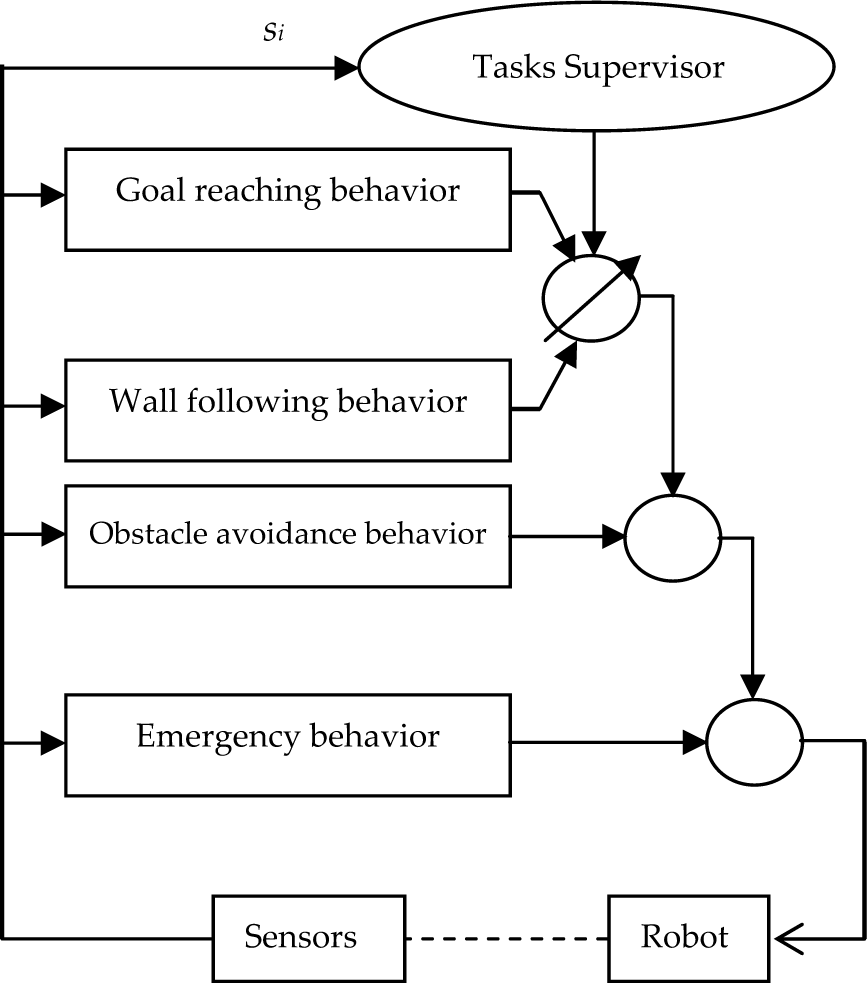
Behavioral based fuzzy control architecture
Each behavior is represented using fuzzy logic rule base and the problem of behavior arbitration can be handled by a fuzzy mechanism. To increase the autonomy of the mobile robot, the task supervisor can be implemented using a decision function based on sensor inputs to decide upon the right behavior the robot should take. This of course could as well include human decisions in case of manual control, which can be programmed. The motion of the robot depends on the task to be achieved. In this work we will be interested in implementing all the behaviors except wall following, since a stereovision camera is used to circumvent this difficulty. We will detail our approach for the modular organization of the fuzzy rule base for each of the path-following and goal reaching behavior and obstacle avoidance behavior.
Figure 1. Behavioral based fuzzy control architecture
2.2.1 Path following behavior
Path following behavior is used to drive the robot along the desired planned path. This behavior allows reaching a target point as well. This behavior is activated when the acquired information from the sensors shows that there are no obstacles. We use the idea that consists of reducing the orientation error a which is the difference between the desired heading and the current heading. Likewise, we aim at reducing the distance error d of the actual robot position with respect to the line (Δ) as it is depicted in Figure 2, such that:


Definition of error variables
The rules generated for this behavior take into account these two input variables and the outputs are chosen to be the right and left velocities of the robot wheels. The tracking fuzzy logic controller is implemented using seven membership functions for the distance and orientation errors and seven as well for the driving wheel velocities. Their forms are chosen arbitrary as it is shown in Figure 3, 4 and 5 respectively.

Membership functions of the distance
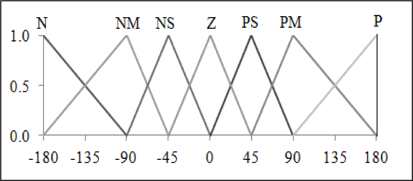
Membership functions of the orientation

Membership functions of the left and right velocities
The output linguistic variables for each fuzzy controller are:
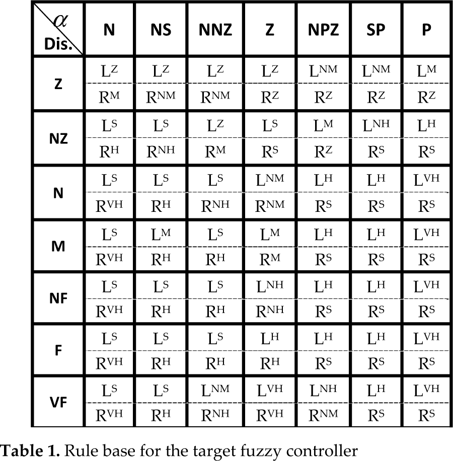
The rule base for the target fuzzy controller is defined in Table 1. Example of such a fuzzy control rule is:
If (d is M Λ α is PM) Then (vl is H Λ vr is S)
Rule base for the target fuzzy controller

Such that, the output of this fuzzy controller are nothing than the left and right velocities of the driving wheels, implemented with seven linguistic variables defined as:
To speed up the process, we choose the centroid deffuzyfication method to get the real values of the left and right driving wheels.
2.2.2 Obstacle avoidance behavior
For mobile robot navigation in cluttered environments, stereo vision cameras represent a means for the provision of rich and complete information, though not very efficient in real time applications for dynamic obstacle detection. Therefore, this type of sensors is inadequate for robots of limited computational power. This problem can be circumvented through the use of ultrasonic sensors (US) which present a viable solution and are used to detect objects which are able to alter the movements of the robot; hence both sensors are used. The use of US sensors and stereo-vision camera and their interaction allow for collision avoidance and path identification in case of local minima or undetermined situations (Fig 6). PowerBot is characterised by front and rear sonar, but we only consider the front one in this work.

Examples of singular configurations
The ultrasonic sensors form the front array and consist of three sets, each covering three distinct regions: front, left and right ahead of the robot and labeled as Left_d, Front_d and Right_d (Fig 7).
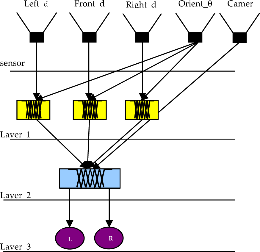
Hierarchical fuzzy control design
The front region is constituted by a set of three sensors, while the left and right regions are constituted by a set of four sensors. Inputs relative to the distance from PowerBot to the detected object are transmitted to the first layer in the hierarchical fuzzy control design. The farthest is retained for computation:

Depending on the current orientation of PowerBot taking “the world frame” as a reference, the values of the orientation are determined with respect to each detected object within the defined region. The side of PowerBot that is closest to the obstacle has a sensitive orientation.
1 st layer:
Four linguistic variables are considered, one for distance, and three for orientations. These are fuzzified separately when obstacles are detected in front, left and right sides respectively. The meaning of each linguistic value should be clear from its mnemonics, therefore we write:

Although there is no restriction on the form of membership functions, the piecewise linear description is chosen. This is shown in Fig 8 and Fig 9. We notice that the universe of discourse of the front target distance takes larger values than that of the left and right target distances. Furthermore, we define the membership functions associated with the input variable as:


Membership functions of the front target distance

Membership functions of the left and right target distance
The shapes of the corresponding membership functions used for these linguistic variables are shown in Fig 10, 11, 12, respectively. The output of this fuzzy controller is the steering angle which is implemented with five linguistic variables defined as:
Membership functions of the left orientation

Membership functions of the right orientation

Membership functions of the front orientation
The membership functions are shown in Fig 13 and are chosen experimentally, and we can notice that they do not overlap. The fact that there is no overlap between these functions is to allow the robot to select exclusively one direction in order to go through it. (e.g. If Steering angle =R- Right, then the robot should move to right without overlap with the RF- RightForward.). In effect, these sets can be considered as classical sets with some degree of truth. Each of these fuzzy sub-controllers (left, right and front) contributes to steering PowerBot away from the detected obstacle. The fuzzy rules are shown in Tables 2, 3 and 4 respectively. Their meaning is explained as follows:

Membership of the steering angle
Rule base for left action


Rule base for right action


Rule base for front action


Akin to target fuzzy logic controller, we choose the centroid deffuzyfication method to get real values of the steering angles responsible to guide the robot away from obstacles.
2 nd layer:
This layer is based on the inputs of the front, left and right fuzzy modules (controllers) of the first layer.
It is used to provide the required motor inputs to steer the robot away from the detected obstacles. It translates the contribution of the three linguistic steering angles into left and right voltage motor outputs (Fig 14). Here the fuzzy rules are derived on the basis of intuitive deduction, and are presented in Table 5. In case PowerBot enters an undetermined situation marked

Membership of the left and right dc-motor velocities
Rule base for obstacle avoidance
The interaction between the US sensors and the stereo visual camera is now explained: when PowerBot finds itself in an undetermined situation, the controllers set the output voltage to zero. In this case, the robot is halted while control is transferred to the camera for analysis. The stereo-vision data are then processed and a decision is taken for safe passage. In case of obstruction, the emergency mode is activated.
3 rd layer:
In this layer (safety layer), the left and right actuators serve to action the movement of PowerBot. Successful movement depends on the right steering angle which is used to smooth the path according to a set of navigation performance criteria. PowerBot navigates using data acquired from its front, left and right sensors. Any detected obstacle will result in offset values at the output of the second layer sub-controller. The third layer provides the required motor voltages that prevent the robot from crushing into such obstacles, i.e., obstacle avoidance capability. In fact, as the robot moves it acquires information from its front, left and right sensors. Any detected obstacles will result in offset values at the output of the second layer sub-controller. The third layer provides the required motor voltages that prevent the robot not to crash into obstacles.
Defuzzyfication
The final output (crisp value) of the Fuzzy Logic controller of left wheel velocity and right wheel velocity can be calculated by:
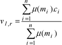
where:
μ(m i ) = Firing area of left and right wheel velocity of the i th rule.
c i = Centroid of the area.
n= total number of parameters.
2.2.3 Emergency behavior
This behavior should have the highest priority. It is activated whenever the robot enters a dangerous zone in which the robot can probably harm its mechanical structure. The emergency distance is specified by the user to maintain the robot only in the safe navigation region. Information from sonar sensors on the left, right and front, checks for the presence of objects when (d < de); where de is the emergency distance. Therefore this behavior works as follows.
2.3 Direct Visual Controlling
2.3.1 Method description
This section presents a visual controlling technique as an alternative to US sensor controlling when the robot faces an undefined situations marked

Stereovision based mapping and path planning module capturing observations at different poses
2.3.2 Stereo Vision based Path-Planning Module (SVPPM)
This module uses a variety of algorithms to achieve Simultaneous Localization and Mapping (SLAM). Our implementation uses a variant of fast SLAM. Here we use a particle filter based distribution model to update robot states and obstacle information. We use stereovision sensor for map building and obstacle avoidance for the obstacles within camera's FOV. Stereovision based map is more comprehensive though not as accurate as a laser scan. This is the same reason that our navigation algorithm is far more robust to complex obstacles, such as obstacles having irregular foot print in all 3D-axes. The data provided by stereo-vision sensor contains a subset of 3D points belonging to an obstacle lying on all axes whereas conventional laser scanners provide us with only a subset of 3D points lying on either XY, YZ or XZ plane for a certain obstacle. Data association is proving to be a challenge in our version of Fast SLAM. This is due to variations in illumination, specular reflection in environment and inconsistent point clouds due to variations in viewing angles.
We use median and average filter along with Bayesian filters to remove noise from specular reflection. A brief overview of SVPPM execution is shown in Figure 16. The stereovision observations are gathered using Bumblebee® XB3 Point grey camera. The camera uses an assembly optimized fast-correlation stereo core that performs Sum of Absolute Differences (SAD) stereo correlation. The method is well known for its speed and robustness. The 3D points representing the environment are down-sampled to achieve real-time processing speed. Finally an ROI that ignores the points above the robot height is selected and is passed onto the ROI sub-sectioning sub-module. This sub-sectioning module is necessary to reduce the time complexity required for performing point cloud manipulation. We were able to reduce time complexity for various filtering algorithm by over 9 times. Next the sub-sectioned point clouds are passed over to filtering sub-module. This sub-module filters the 3D point cloud for false positives that arise due to specular reflections and direct exposure to highly bright indoor lights. These filtered point clouds are then passed through a RANSAC based plane fitting method to detect floor and obstacles. Obstacles as small as wires, stationary and carpet deformities were successfully detected by our self-developed floor segmentation method listed in detail at [19]. The detected obstacles are then accurately updated on a global grid-map. This grid map is used to plan-paths whenever a path is requested from any other module within the system. We use a grid that covers an area of over 300 square-meters in experiments. Each grid-cell is limited to a size of 0.1 square-meters. Each grid-cell holds a value that is normalized between 0.0 and 1.0. Here 0.0 represents an absolute belief that the cell contains an obstacle and 1.0 indicates an absolute belief that the cell is free for navigation. A maximum threshold value of 0.4 was empirically determined to be the maximum value a grid-cell can have to be considered as an occupied grid-cell. A*-algorithm is used to determine the free path between two given points. The free paths between any two points are always optimal given the provided obstacle scenario is accurate. In case obstacle scenario is significantly changed so much so that it affects the planned path, A*-algorithm is used to re-plan the path to the goal. The planning and re-planning delays are less than a second long, so there are no issues for performance degradation within path-planning routine.

Stereovision mapping and path-planning module flowchart
2.4 Motor control
Three movements are expected: forward, turn left, and turn right. Depending on the data signal received by sensors, we expect the robot to perform smooth movements given the task's distance and orientation. As a result of the mutual exclusivity of left and right turns, we can get multiple behaviors such as, wall following, goal reaching, obstacle avoidance and emergency behavior. The movement of the robot depends on the movement of each motor.
The angular speeds of the motors are determined on the basis of a fuzzy rule base where the inputs and outputs are the steering angles and angular speeds respectively.
3. Experimental results
3.1 The mobile robot description
The mobile robot used in this work is PowerBot, a wheeled mobile robot from Adept mobile robots Inc. It is an automated differential drive guided vehicle specially designed and equipped for autonomous, intelligent delivery and handling of large payloads (Figure 17). It is one of the many mobile robots Pioneer families, which are research and development platforms that share a common architecture, foundation software, and employ artificial intelligence-based client server robotics controls. The PowerBot platform operates as the server in a client-server environment. The Advanced Robotics Interface for Applications (ARIA) is the ideal platform for integration of the user robot-control software, since it really handles the lowest-level details of client-server interactions, including serial communications, command and self-information packet processing, cycle timing and multithreading, as well as a variety of accessory controls. PowerBot has a sturdy aluminum body, balanced drive system reversible DC motors. It is relatively very strong and quite large; it can carry a load of up to 100 Kg on its flat top surface, and navigate with a speed of up to 1.6m/sec [20]. PowerBot is provided with Ultrasonic sensors, optional vision system and laser range-finder accessories attach in front and integrates a full-size PC.

PowerBot side view
a) Sonar
PowerBot comes standard with two sonar arrays, one in front and one in the rear. We depict in Figure 18 the PowerBot front sonar arrays. Sonar geometry is identical on each array, one sonar on each side. Each array contains 12 sonar sensors partitioned around the perimeter of the robot with every one separated by a 10° interval, and two other at the side. Together, the 28 front and rear sensors provide 360° of nearly seamless sensing.
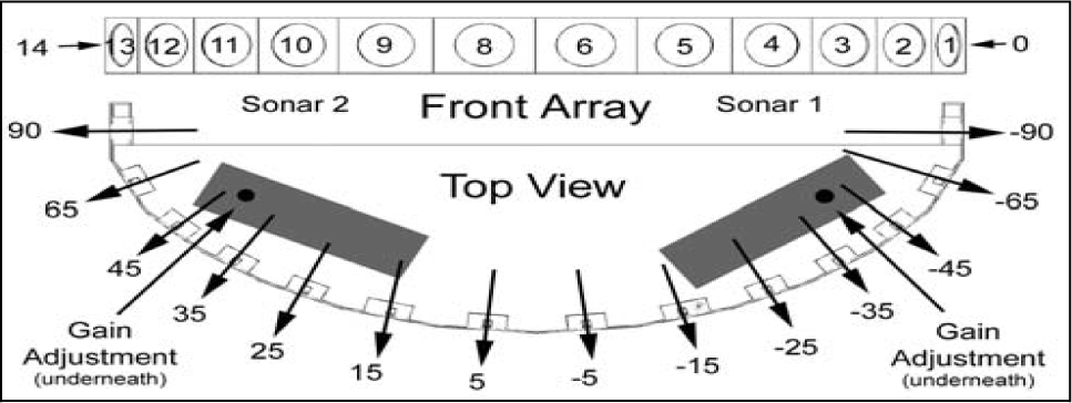
PowerBot front sonar arrays [21]
b) The camera Bumblebee XB3
Powerbot comes with an optional camera, however for our concern; we used Bumblebee XB3 camera (mounted on top of the robot to provide more information on the surrounding environment. The Bumblebee XB3 is a 3-sensor multi-baseline IEEE-1394b (800Mb/s) stereo camera designed for improved flexibility and accuracy [22]. It features 1.3 mega-pixel sensors and has two baselines available for stereo processing. The extended baseline and high resolution provide more precision at longer ranges, while the narrow baseline improves close range matching and minimum-range limitations. It has a resolution 1280times960 at 15FPS, and 6mm focal length. One of the most important specifications of this camera is that it is pre-calibrated.
c) The Pan-Tilt Unit
The Bumblebee XB3 camera is attached to the robot by means of a Pan Tilt Unit (D46-17 by FLIR) (Figure 19).

Pan-Tilt Unit from FLIR
The pan-tilt unit enables the Bumblebee camera to be rotated and tilted at speeds up to 300-degrees per second. The pan-tilt resolution is 0.013 degree which is more than enough for our application. The tilt range available is from 47° to +31° from level (78° range). The available pan range is +/- 159°. We use custom designed module to communicate with the unit via RS-232.
3.2 The Experiment Test-Bed
The experiments for this paper have been conducted within a controlled lab environment. The experimentation area was limited to 7-meters x 4-meters (28 sq. meters). The area was calibrated with markings having 0.5 meter resolution. This was done in order to double check the ground-truth for the robot motion control and path-planning verification. The ground surface was an even carpet. The dead-reckoning related parameters for the robot were calibrated to keep the odometry error to the minimum. Lightening conditions were not particularly controlled but care was taken to avoid highly specular surfaces that can cause spurious observations for stereovision rectification algorithm.
3.3 Execution time and Path-Planning Performance
A total of 90 test runs were conducted with random obstacle configurations on the lab floor. Numbers of occupied cells were gradually increased after an interval of 30 tests. Numbers of occupied cells in any configuration were considered as a measure of map complexity. This measure is elaborated in detail in [23]. The results showing the length of the planned path and time consumed in path planning process are tabulated in Table 6. The run-time shown for each map-complexity level is an average of 30 run-times of path-planning algorithm executed for the corresponding map-complexity level. It must be reminded here that our proposed motion control architecture divides the overall robot path into two categories of sub-paths i.e. fuzzy control based paths and Stereo-Vision based grid-map paths. Thus when compared to other grid-map based path planning algorithms, the proposed architecture only executes path-planning algorithm over the map vertices that cannot be traversed using fuzzy control. The length of overall path depicted in Table 6 includes both categories of paths handled by proposed architecture. The machine used to calculate new paths was an ASUS gaming laptop with an Intel Core i-7 2.20 GHz processor and a 12 GB RAM.
Results showing the length of the planned path and time consumed in path planning process

3.4 The Experiment Scenarios and Results
Various scenarios were set-up within the test-bed area to test the robustness, accuracy, adaptability and efficiency of the proposed system. Each scenario is described and relevant testing parameters and results are listed for reference. Note that the x-y data measurements are stored and used thereafter by Matlab to get the consequent graphs. This scenario is designed to test the Fuzzy-Logic motion controller. We note here that the maximum possible speed supported by our robot is 1,6 m/sec which is dangerously high for indoor environment [24].
Given the fact that the experimentation area was limited to 7-meters x 4-meters (28 sq. meters) and the robot needs to stop for any dynamic obstacle and also being mounted with a camera through which it needs to take sharp images, the maximum speed of the mobile robot well suited to such contingencies is 0.35m/s.
• No-Obstacles Scenario
Under this simplistic scenario the robot is expected to take a straight path towards the goal without any significant deviation from a straight line path.
The robot is expected to follow a smooth path. The robot is expected to reach the goal following an optimal path.
The result of this experiment is shown in Figure 20, where we can see the path of the robot from its starting position to the target. The velocity curve for this scenario is shown in Figure 21.

No-Obstacles Scenario
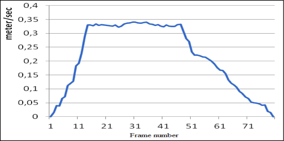
Profile of the velocity for the no-obstacles scenario
• Random-Obstacles Scenario
The obstacles are scattered in a random fashion across the test-bed area. The Fuzzy-Logic motion controller (FLMC) is expected to robustly guide the robot towards the goal position without collision with any of the obstacles.
The robot is expected to follow a smooth path. The robot is expected to avoid obstacles. The robot is expected to reach goal following an optimal or sub-optimal path. The robot is expected to reach goal without requesting assistance from stereovision path-planning module (SVPPM) since the obstacles have been placed in such away the robot does not enter a Cul-de-Sac scenario.
The result of this experiment is shown in Figure 22, where we depict the evolution of the mobile robot among static obstacle, while Figure 23 shows the profile of the corresponding velocity.

Random-Obstacles Scenario
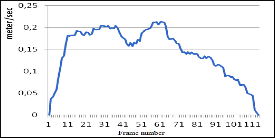
Profile of the velocity for the random obstacles scenario
• Cul-de-Sac Scenario
The obstacles are placed within the test-bed area in such a way they form a Cul-de-Sac scenario for the mobile robot. Under this scenario the Fuzzy-Logic motion controller (FLMC) is expected to guide the robot towards the goal position until a cul-de-sac scenario is encountered. At this stage the robot is expected to seek path towards the goal from stereovision based path-planning module (SVPPM). The robot is expected to reach the goal while exhibiting the path-following behavior. At this stage:
The robot is expected to follow a smooth path. The robot is expected to avoid obstacles. The robot is expected to enter the Cul-de-Sac scenario following an optimal or sub-optimal path. The robot is expected to reach goal via an optimal path produced by stereovision based path-planning module (SVPPM).
The result of this experiment is shown in Figure 24 where one can see the first path as a result of the FLMC and the second obtained by SVPPM. The corresponding velocity profile is as shown in Figure 25. The path generated by SVPPM on a grid-map for this scenario, Stereovision based SLAM, is shown in Figure 26. The radius of the circle in the figure represents the robot radius for path-planning purposes.
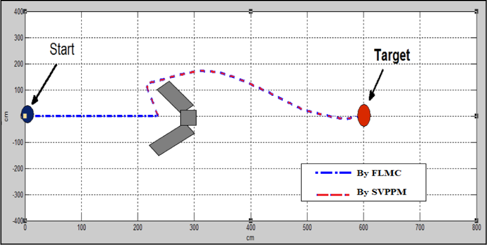
Cul-de-Sac Scenario
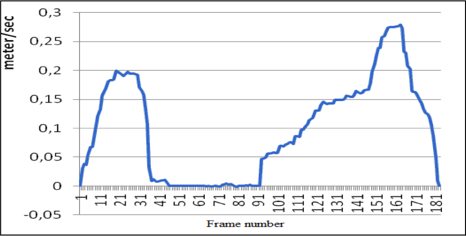
Profile of the velocity for the cul-de-sac scenario
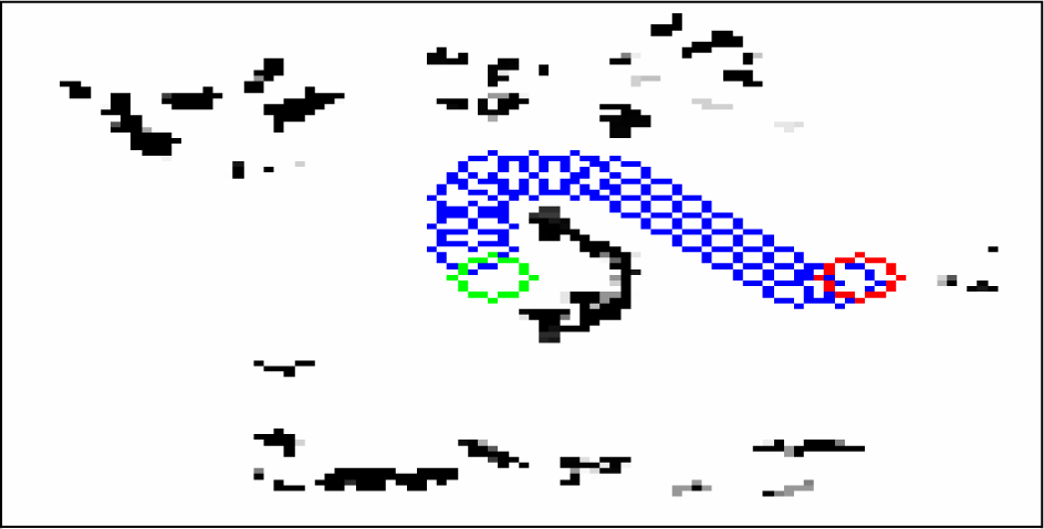
SVPPM generated path on a grid-map. Green marks: starting position, red marks: target point.
• Cul-de-Sac with Random Obstacles Scenario
The obstacles are placed in a random way across the test-bed area. The condition for entering a cul-de-sac scenario is relaxed in this case so now the robot is expected to enter a cul-de-sac scenario even when the obstacles are farther away and robot is not trapped. This relaxed condition will enable the robot to quickly get out of areas heavily crowded with obstacles. Using only the fuzzy-logic motion controller (FLMC) to escape from such areas will consume more time and would cause degradation in optimality of the path. In this scenario the Fuzzy-Logic motion controller is expected to robustly guide the robot towards the goal position as far as possible until a relaxed cul-de-sac scenario is faced by the robot. The robot is expected to complete the rest of its path towards the goal by seeking path points from stereovision based path-planning module (SVPPM).
The robot is expected to enter the relaxed Cul-de-Sac scenario any time during the execution via an optimal or sub-optimal path. The robot is expected to reach goal via an optimal path produced by stereovision based path-planning module (SVPPM). The robot is expected to follow a smooth path. The robot is expected to avoid obstacles.
The result of this experiment is shown in Figure 27, where we can depict the path followed by the mobile robot which once more is the result of the FLMC and the SVPPM. The corresponding velocity profile is as shown in Figure 28. The path generated by the SVPPM for the above scenario, on a grid-map generated by Stereovision based SLAM is shown in Figure 29.

Cul-de-Sac with in Random Obstacles Scenario

Profile of the velocity in a Cul-de-Sac with Random Obstacles Scenario
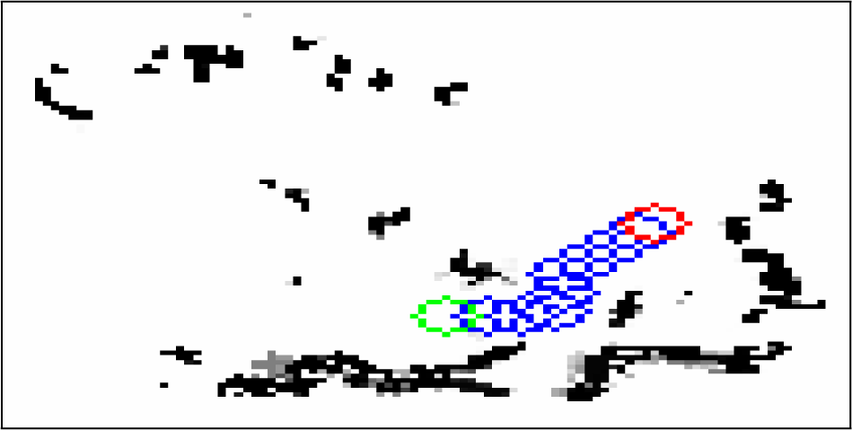
SVPPM generated path on a grid-map, Green marks: starting position, red marks: target point.
•Dynamic Obstacles Scenario
The dynamic obstacle in case of this scenario is a pedestrian. The pedestrian walks in front of the robot in a straight line. Only the fuzzy-logic motion controller (FLMC) is used to avoid the pedestrian. In case of any other kind of dynamic obstacles as well, the proposed system will allow FLMC to take precedence over SVPPM. In this scenario the Fuzzy-Logic motion controller is expected to robustly guide the robot towards the goal position while avoiding the walking pedestrian safely.
The robot is expected to follow a smooth path. The robot is expected to avoid dynamic obstacles. The robot is expected to reach the goal while deviating from its path minimally to avoid the dynamic obstacle.
The result of this experiment is shown in Figure 30, where we can see the path of the pedestrian and that of the mobile robot generated by the FLMC. The profile of the corresponding velocity is shown in Figure 31. As we can observe, the robot stopped for a brief moment and deviated from its path minimally to avoid the dynamic obstacle. Three consecutive snapshots for such a scenario are taken for the purposes of illustration are reported in Figures 32, 33 and 34.

Dynamic obstacle scenario.

Profile of the velocity in a Dynamic obstacle scenario

The pedestrian approaching the mobile robot path

The pedestrian crosses the mobile robot path

The pedestrian moves away safely from the robot's path.
4. Comparison study and Performance metrics
In order to evaluate our proposed scheme, we made a comparison with the selected approaches [25], [26] and [27]. Our intention is not to cover every approach; this is merely for sake of illustration.
In [25], a parallel processing strategy is presented. Their method is based on two fuzzy based controllers where each input of the fuzzy units contributes to the final decision. The main idea of the approach combines with the Khatib's potential field method and brooks subsumption structure. Although global and local path planning are integrated within the system, no treatment of local minima is given in comparison to the method given in this paper, where the robot seeks the safe path, which is implemented by the stereovision based path planning module.
Paper [26] proposed mobile robot navigation based on a variety of behavior algorithms implemented using fuzzy reasoning. The robot navigation is comprised of four behaviors whose outputs are the steering angle and the velocity of the mobile robot. To deal with behavior conflict, the authors added a supervision layer which defines the priority of each behavior. The proposed methodology depends largely on the compilation of the rules, which demand a lot of skill from the human expert. On the other hand, the method does not offer to the robot the shortest path to the goal in case of critical situations in contrast to our approach. In effect, to perceive the environment with better accuracy, our approach used US sensors together with stereo-vision camera. The mobile robot senses the environment with the US sensors to navigate safely among obstacles, while finding the best path using stereo vision camera when it is in crucial situations. Correctness and completeness of the fuzzy rules are implemented in a systematic manner by using multilevel architecture.
Since the proposed approach uses fast-SLAM algorithm in its standard form [27], we only claim our approach to be robust and less resource hungry. The fact that the proposed approach produces sub-optimal paths in comparison to optimal paths produced by fast-SLAM in conjunction with A* algorithm, makes our claim focused on robustness and resource optimization rather than path optimality. A visual comparison is presented in Figures 35 and 36 that shows paths followed by a robot using the proposed method and paths followed by the robot using fast-SLAM (and A* for path planning). As evident, the path generated by our approach is sub-optimal but the proposed method does not rely on computationally expensive Stereo-vision sensors under normal circumstances. It is only when a critical threshold is breached that our method requests help from state-of-the art method such as (stereo-vision based) fast-SLAM.

Comparison study in case of a cul-de-sac situation

Comparison study in case of a relaxed-scattered-cul-de-sac
The critical threshold can be tuned in a way that decides the proportion between the two kinds of sub-paths generated by our approach, i.e. fuzzy control based sub-paths and stereo-vision fast-SLAM based sub-paths.
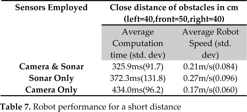
In addition to the previous experiments, we introduce some performance metrics to evaluate the proposed approach. For each of a total of nine experiments, 10 trials were conducted. This makes the total number of trials equal to 90. Phase 1 will have 3 experiments conducted while only employing sonars. Phase 2 will have 3 experiments while only using camera and Phase 3 will have 3 experiments while using both sensors. In each phase, we will have one experiment with LONG minimum distance to the obstacles, one with SHORT minimum distance to the obstacles and one with OPTIMAL minimum distance to the obstacles from the robot. The following metrics will be recorded during all experiments.
1. Computational time
This parameter is the time taken by the stereo capturing process, communication of point cloud to the server, mapping, path-planning and path point generation.
2. Robot Speed
This parameter represents the robot velocity in units of meters per second during the experimentation.
3. Minimum distance of the robot to the obstacles
This parameter ensures that the distance between the robot and the obstacles in the environment does not cross below the defined distances from the front, left and right sides of the robot. Robot path (i.e. series of X-coordinate and Y-coordinate points) are recorded for all trials and are averaged to calculate an average path for each experiment. Obstacle configuration was not changed throughout the trials so that path-planning performance can be compared. These paths are shown in Figures 37 till 45. Many trials were conducted and to test how close these values are to the average, standard deviation was computed and values are inserted in their corresponding cells in Tables 7, 8 and 9. Computational time, robot speed and minimum distance of the robot are calculated by taking average of 10 trials for each experiment.
Sonar & Stereo-camera employed with optimal distance to the obstacles.

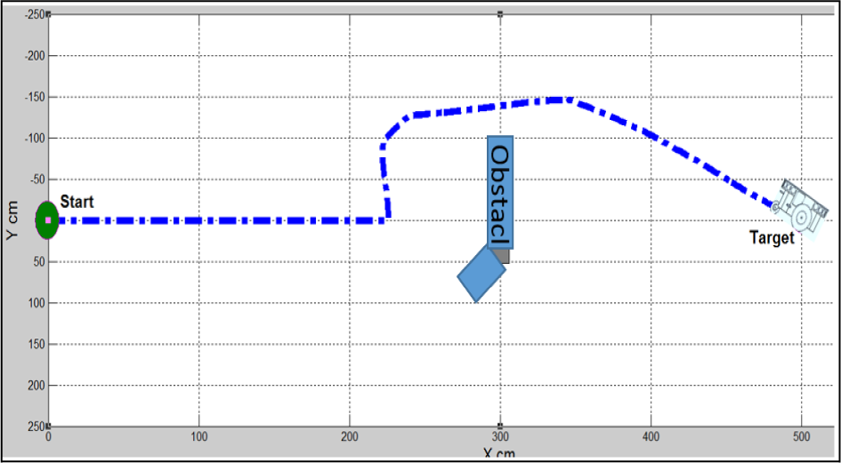
Sonar & Stereo-camera employed with close distance to the obstacles. Out of 10 trials, 3 trials could not complete navigation since the location of the robot was dangerously close to the obstacles when the robot entered Cul-de-sac scenario.

Sonar & Stereo-camera employed with long distance to the obstacles

Only Sonar employed with optimal distance to the obstacles. In this scenario the robot was unable to continue navigation beyond the point shown above. The navigation was terminated since the fuzzy rules cannot handle such an obstacle scenario.

Only Sonar employed with close distance to the obstacles. In this scenario the robot was unable to continue navigation beyond the point shown above. The navigation was terminated since the fuzzy rules cannot handle such an obstacle scenario.

Only Sonar employed with long distance to the obstacles. In this scenario the robot was unable to continue navigation beyond the point shown above. The navigation was terminated since the fuzzy rules cannot handle such an obstacle scenario.

Only Stereo camera employed with optimal distance to the obstacles.

Only Stereo camera employed with close distance to the obstacles.

Only Stereo camera employed with far distance to the obstacles.
Robot performance for a short distance
Robot performance for an optimal distance

Robot performance for a long distance

Results are shown in the following Tables 7, 8 and 9; where it can be deduced the good performances achieved by the algorithm that uses both sensors. One interesting experiment leading to a failed mission is the one presented in this paper. Considering Figures 40, 41 and 42, one can remark that the robot stops, and the mission is aborted. This is due to the fact that robot US-sensor can cover only a limited zone of the look-ahead area with three groups of front US-sensors having each a cone of 60 degree. For the obstacle encountered in this case, it is considered local minimum and the robot has no decision to take so it stops. The analysis of these three scenarios reveals the superiority of the proposed algorithm that uses both stereo vision camera and the US-sensor to execute a given mission by generating safer trajectories with less energy.
5. Conclusion
In this paper, we have described the motion control for autonomous robot navigation, focusing on its kinematics characteristics and on its behavioral based fuzzy control architecture. We used the ActivMedia Robotics Interface for Applications (ARIA) platform to integrate our C++ program to control Powerbot mobile robot. Path planning and obstacle avoidance behaviors have been presented. Avoidance obstacle behavior is one of the key issues for navigation improvement. In order to increase the autonomy of the robot and its ability to successfully execute navigation tasks in cluttered environments, we have presented an ordered hierarchical architecture based on fuzzy reasoning. Accordingly, we proposed and implemented a stereo vision camera to assist the US sensors in an undetermined situation such as a “cul-de-sac”. A number of scenarios have been experimented in order to demonstrate the robustness of the approach, leading every time to successful outcomes. This paper contributes for a systematic approach using fuzzy logic reasoning and control based on US sensors and stereo vision information. As an extension to this work, we aim at exploiting Powerbot possibilities to designing control laws that take into account the dynamic behavior and the inertia effect. We will focus on our research on outdoor navigation where we expect to see Powerbot operating in an unstructured and unknown terrain.
6. Acknowledgments
This work is supported by NPST program by King Saud University (Project No. : 08-ELE300-02).