
Abstract
A Lookup-Table (LUT) based design enhances the processing speed of a fuzzy obstacle avoidance controller by reducing the operation time. Also, a LUT sharing method provides efficient ways of reducing the LUT memory size. In order to share the LUT which is used for a fuzzy obstacle avoidance controller, an idea of using a basis function is developed. As applications of the shared LUT-based fuzzy controller, a laser-sensor-based fuzzy controller and an ultrasonic-sensor-based fuzzy controller are introduced in this paper. This paper suggests a LUT sharing method that reduces the LUT buffer size without a significant degradation of the performance. The LUT sharing method makes the buffer size independent of the fuzzy system's complexity. A simulation using MSRDS (Microsoft Robotics Developer Studio) is used to evaluate the proposed method. To investigate the performance of the controller, experiments are carried out using a Pioneer P3-DX with LabVIEW as an integration tool. Although the simulation and experiments show little difference between the fully valued LUT-based method and the LUT sharing method in terms of the operation time, the LUT sharing method reduces almost 95% of the full-valued LUT-based buffer size.
Introduction
Autonomous navigation algorithms are applied to various applications for mobile robots to drive toward their target position without a remote control program. In the mapping step of an autonomous navigation application, the robot acquires the location and contour information of obstacles from sensors and updates its navigation map. A navigation path from the current position to the target position on the map is determined by the updated map data. If there are no changes in the map during the robot navigation process, obstacle avoidance is not necessary because a well-defined navigation path will lead the robot to the target position safely. Even in the event that unexpected obstacles suddenly appear on the navigation path, the robot is required to perform obstacle avoidance in order to navigate the planned path without colliding with these types of obstacles. To escape the unexpected obstacles and continue toward the target position under real-time navigation, the robot should determine its steering direction and velocity instantly. This paper is focused on performance improvement and implemental optimization for a fast real-time obstacle avoidance system of robot navigation.
There are several algorithms pertaining to robot obstacle avoidance, including potential field algorithms [1], vector field histogram algorithms [2], and fuzzy controller algorithms [3]. The fundamentals of fuzzy controller methods were presented by Wang [4], Palm [5], Passino [6], Aguirre [7], and others [8, 9]. As a result of these papers, fuzzy controller methods have more advantages in real-time applications because they provide simpler and more intuitive methods of robot obstacle avoidance. This is why we chose fuzzy controller methods for obstacle avoidance here. Mbede [10] proposed a neuro-fuzzy motion controller, and Lilly [11] presented a P/N fuzzy obstacle avoidance controller. Lilly's work provided a more intuitive method for robot obstacle avoidance through its use of negative fuzzy rules to eliminate redundant fuzzy rules. Kiendl [12] and Branson [13] also presented methods of utilizing negative rules in fuzzy systems. The fuzzy controller in this paper is based on the P/N rule fuzzy controller method proposed in Lilly's paper [11]. We verified the performance of the previous P/N rule fuzzy controller method using a robotics simulator in MSRDS (Microsoft Robotics Development Studio) 2008 [14]. We also devised an improved algorithm based on the previous P/N rule fuzzy controllers, verified them in a simulator, and experimented in a real environment.
In Section 2, the fundamentals of the P/N rule fuzzy controller and the full LUT-based design of the P/N fuzzy controller are introduced. The proposed LUT sharing method for the controller is described in Section 3. Section 4 and Section 5 present the laser range-finder-based 50-rule P/N fuzzy controller and the ultrasonic-sensor-based 18-rule P/N fuzzy controller, respectively. Simulation and experimentation results are shown in Section 6. Finally, concluding remarks are summarized in Section 7.
A Positive/Negative rule fuzzy controller and its full-LUT-based design
A Positive/Negative rule fuzzy controller
Fuzzy rules of traditional fuzzy systems only describe the operations that are to be run. In Positive/Negative (P/N) rule fuzzy system theory, the concept of negative fuzzy rules was introduced to prescribe actions to avoid rather than execute. Two types of rules, positive rules and negative rules, are used in a P/N rule fuzzy controller. Positive-rules derive the proper output of the P/N-rule-based fuzzy system, comparable to typical fuzzy system rules. In contrast, negative rules cause the fuzzy system not to produce improper fuzzy output. The P/N rule fuzzy system can be applied to obstacle avoidance for the autonomous navigation of mobile robots. Positive rules direct the robot to a target place and negative rules prevent the robot from colliding with obstacles. The effect of positive rules is dominant in a non-obstacle environment because negative rules begin to affect navigation only when obstacles appear on the navigation path of the robot. If the detected obstacles are far from the robot, negative rules rarely affect the system. As the obstacles come closer to the robot, the negative rules dominate the system.
Full-LUT-based design of a Positive/Negative rule fuzzy controller
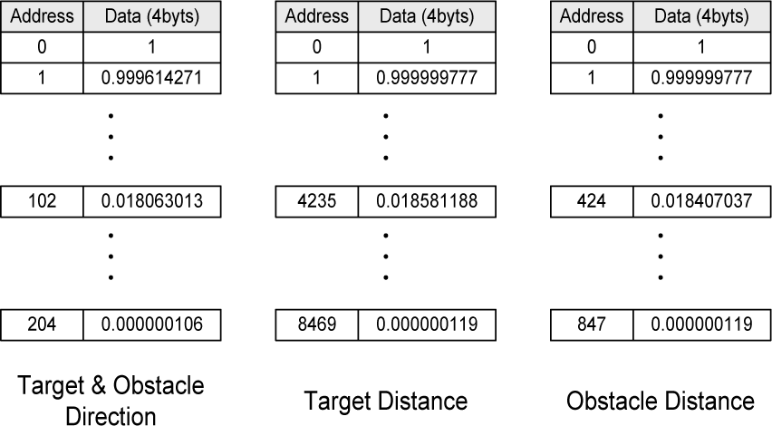
For secure navigation for mobile robots, the computation delay of the obstacle avoidance controller is one of the most important factors. To reduce the delay, we decided to reduce the computational complexity of the controller. It is not to be denied that faster decision when avoiding obstacles contributes to more accurate avoidance. In our design, we adopted a P/N fuzzy controller method which is simpler and more intuitive for robot obstacle avoidance. However, fuzzy membership functions formed as Gaussian distribution curves are the most critical problem related to fast operations because the fuzzy controller should process numerous floating point operations to calculate the fuzzy membership degrees. The computations for fuzzy membership degrees could be a burden that causes difficulties with real-time navigation. Therefore, we attempted to reduce the computations for membership degrees through the use of the LUTs of membership functions. The basic idea is that the fuzzy controller does not need to calculate the membership function degree upon the receipt of sensor data each time, as all membership functions and their each output values corresponding to their input values are previously determined according to the characteristics of the function. Therefore, it is possible to store all membership function data in the LUTs in advance and search for membership degrees from the LUTs without any computational time. Fig. 2 illustrates the process of obtaining fuzzy membership degrees from the LUT. The LUT buffers of all fuzzy membership functions are shown in Fig. 3. If the fuzzy controller obtains each membership degree from LUT buffers, the robot can reduce the processing time and perform more frequent obstacle-avoidance operations because the operation delay in the multiplication of the floating point operands is eliminated.

Fuzzy membership degree acquisition on lookup-table based architecture
Lookup-table (LUT) buffers of full-LUT-based architecture

Fuzzy membership degree acquisition using a shared lookup-table
It is quite attractive to use LUTs that are capable of rapid operations in a fuzzy controller, but there are also disadvantages in a LUT-based design. To maintain the LUTs of membership functions, the fuzzy controller should guarantee a sufficient size of the buffer memory for the LUTs. Because a large LUT memory is a burden on the system, we tried to reduce the memory through the use of a shared LUT. The shared LUT contains the function values of a basic Gaussian distribution function that we defined. The equation of the basis function can be expressed as follows:

The variance of the basis function, σ
BasisFunction
, is set to 128 for the 50-rule P/N fuzzy controller. This idea stems from the fact that all membership functions of our fuzzy controller are based on a Gaussian distribution which is characterized by the variance (σ) and the center (c). Therefore, each membership function's output value is simply obtained from the basis function by converting the input value x
input
into the proper converted value X
Converted
, which is calculated as follows:

The input data from a laser range finder (LRF) are discrete and are converted into integer values so that they can be used as the indexes of the LUTs. The shared LUT is also indexed by integral numbers to simplify the use of buffers. Because the calculation result, x Converted , can contain a decimal fraction value, it is not possible to provide the output value of the original membership function using the shared LUT because it provides only the output values of integral inputs. Although we cannot use non-integer indexes, we can obtain an approximate value by rounding off x Converted to its nearest integer.
As shown above, f
basis
is a Gaussian distribution function; hence, the left part of the basis function in the shared LUT can be eliminated to remove redundancy. The absolute values of the inputs are used to generate an indexing address corresponding to the left part of the basis function. Finally, the indexing address of the shared LUT is calculated as follows:

Fig. 3 shows a diagram of the fuzzy membership degree acquisition process using the LUT sharing method. The Address Generator generates the indexing address of the shared LUT, Addresslut; the calculated address is proper for the characteristics of each of its membership function. In each indexing address, 32-bit floating point data is stored. Also, the range of indexing address is between 0 and 511, as shown in Fig. 3. If the calculated address, Addresslut, exceeds a length of 511, we change the value to 511 and the LUT releases 0 as the output. This also indicates that we consider output values below 0.000000119 as 0 in order to reduce the buffer size.
After reading the output of the function from the shared LUT, Compensator compensates for the output value, as it is not identical to an expected membership degree. However, this may not be necessary when the errors between the shared LUT outputs and the original output values are too small to affect the navigation performance. We confirmed this in simulations and determined it was feasible to eliminate Compensator from the design.
Design of 50-Rule P/N Fuzzy Controller
The 50-rule P/N fuzzy controller is designed with two types of input parameters, the first is sensor data from a laser range finder and the second is the relative target position based on the current position of the robot. Fig. 4 shows the measurement data from the laser range finder. The laser range finder sensor provides the distance vectors of directions over 180 degree with an angular resolution of 0.5 degrees. To simplify the fuzzy system, we converted the scale of inputs into integer values by multiplying the input value by 2. Once the target position is determined, the position is a constant on the navigation map. However, the relative target position varies according to changes of the current robot position. As the robot moves, the robot controller should update the relative target position, which consists of a target distance and a target direction. The output of the fuzzy controller is the steering direction of the robot. In a real application, however, the controller converts the direction information into values for steering, as in the velocities of two wheels.

Measurement of the laser range finder
In the 50 P/N fuzzy rules, 25 positive rules are related to the target position and 25 negative rules are related to the positions of multiple obstacles. The fuzzification of the 50-rule P/N fuzzy controller for the laser-range-finder-based obstacle avoidance method is explained in the next section.
Fuzzification of the input is described by the membership functions shown in Fig. 5. Each membership function of a fuzzy input is a Gaussian distribution function. These are expressed as Eq. (4)

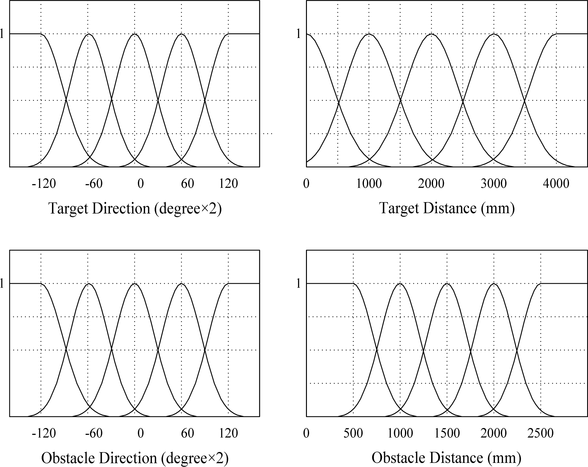
Membership functions of the designed 50-rule fuzzy controller
where c denotes the center of the distribution and σ denotes the variance of the function. Table 1 represents the c and σ values of each fuzzy membership function. The fuzzy sets Hard Left (HL), Soft Left (SL), Straight (S), Soft Right (SR), and Hard Right (HR) are for the fuzzy inputs of the target or the obstacle direction. In addition, Zero (Z), Very Near (VN), Near (N), Far (Far), and Very Far (VF) are related to the fuzzy inputs of the target or the obstacle distance. The output fuzzy sets Hard Left (HL), Left (L), Soft Left (SL), Straight (S), Soft Right (SR), Right (R), and Hard Right (HR) are for positive rules, while
Characteristics of the Fuzzy Membership Functions of the 50-rule P/N Fuzzy Controller

The expert-provided positive rule base is shown in Table 2 and the negative rule base is given in Table 3. The positive rule base can be represented by the following rules:
Rule Base of the 25-rule Positive Fuzzy System (Expert-Provided)

Rule Base of the 25-rule Positive Fuzzy System (Expert-Provided)
Rule Base of the 25-rule Negative Fuzzy System (Expert-Provided)

If xTargetDirection is HL and xTargetDistance is Z then y is HL
If xTargetDirection is HL and xTargetDistance is VN then y is HL
If xTargetDirection is HL and xTargetDistance is N then y is L
⋮
If xTargetDirection is HR and xTargetDistance is VF then y is SR.
The negative rule base in Table 3 is represented in the same manner of the above rules, as follows:
If xObstacleDirection is HL and xObstacleDistance is Z then y is not HL
If xObstacleDirection is HL and xObstacleDistance is VN then y is not HL
If xObstacleDirection is HL and xObstacleDistance is N then y is not L
⋮
If xObstacleDirection is HR and xObstacleDistance is VF then y is not SR.
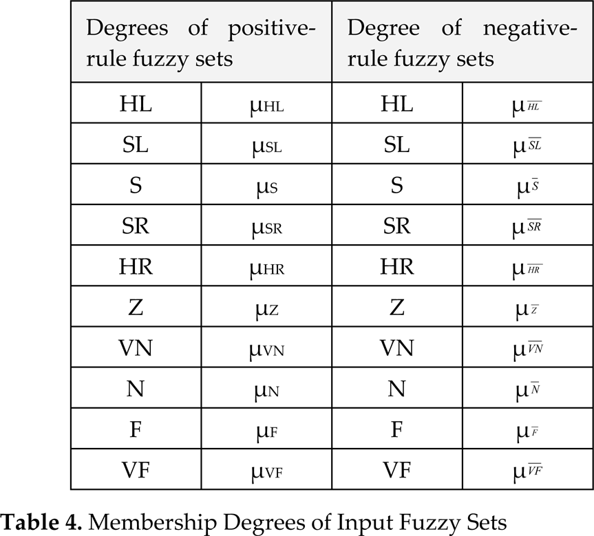
The notation of the membership degree of each fuzzy set is expressed as shown in Table 4. The weight of the positive rule '
Membership Degrees of Input Fuzzy Sets
Similarly, the other combined degrees are calculated as follows:

Finally, the output value of the 50-rule P/N fuzzy controller is calculated as the weighted average of all output fuzzy sets:

The weights of the output fuzzy sets are as follows:

Design of 18-Rule P/N Fuzzy Controller
The 18-rule P/N fuzzy controller is designed as an ultrasonic sensor based obstacle avoidance system for mobile robots. Unlike the laser range finder, ultra-sonic sensors implemented here have an angular resolution of 30° and are arranged with 7 sensors, as shown in Fig. 6. Each sensor detects the nearest obstacle in front of the sensor within a distance from 25mm to 3m using a 30° angular range. Because its angular resolution is relatively low compared to a laser range finder, we designed a simpler fuzzy controller based on 18 rules. In a manner similar to that of the 50-rule P/N fuzzy controller, 9 positive rules are related to a target position and 9 negative rules are related to the positions of multiple obstacles.
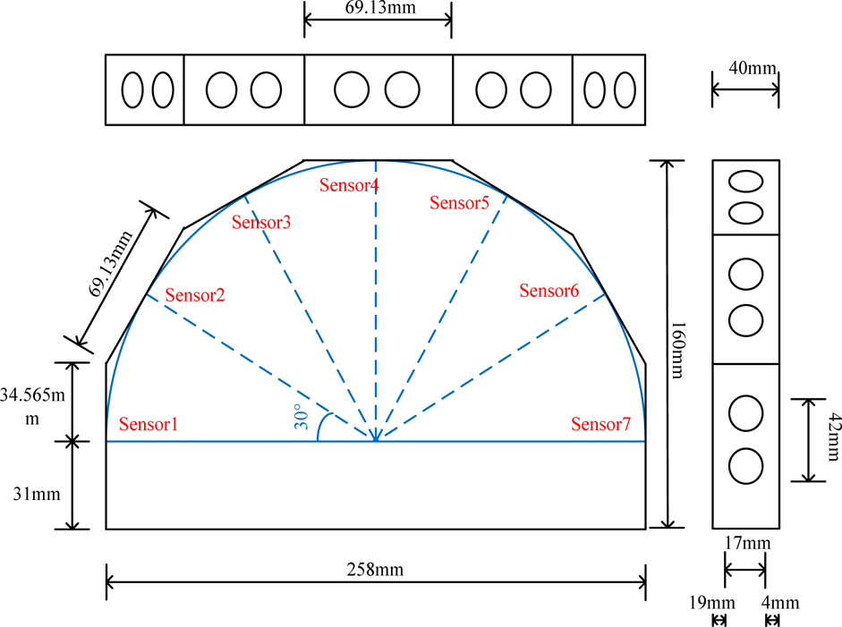
Implementation of the ultrasonic sensors for the 18-rule fuzzy obstacle avoidance fuzzy controller
Fuzzification of the 18-rule P/N fuzzy controller can be described by the membership functions shown in Fig. 7. Each membership function is a Gaussian distribution function. Table 5 represents the c and σ values of each fuzzy membership function. The fuzzy sets, Left (L), Straight (S), Right (R), are for the fuzzy inputs of the target or the obstacle direction. Also, Zero (Z), Near (N), and Far (Far) are related to the fuzzy inputs of the target or the obstacle distance. The output fuzzy sets Hard Left (HL), Left (L), Soft Left (SL), Straight (S), Soft Right (SR), Right (R), and Hard Right (HR) are for positive rules, while

Membership functions of the designed 18-rule fuzzy controller
Characteristics of Fuzzy Membership Functions of the 18-rule P/N Fuzzy Controller

Each rule base of positive and negative rules is shown in Table 6 and Table 7, respectively. The positive rule base can be represented by following rules:
Rule Base of 9-rule Positive Fuzzy System (Expert-Provided)

Rule Base of 9-rule Positive Fuzzy System (Expert-Provided)
Rule Base of the 9-rule Negative Fuzzy System (Expert-Provided)

If xTargetDirection is L and xTargetDistance is Z then y is HL
If xTargetDirection is L and xTargetDistance is N then y is L
If xTargetDirection is L and xTargetDistance is F then y is SL
If xTargetDirection is S and xTargetDistance is Z then y is S
If xTargetDirection is S and xTargetDistance is N then y is S
If xTargetDirection is S and xTargetDistance is F then y is S
If xTargetDirection is R and xTargetDistance is Z then y is HR
If xTargetDirection is R and xTargetDistance is N then y is R
If xTargetDirection is R and xTargetDistance is F then y is SR
The negative rule base in Table 7 is also represented as follows:
If xObstacleDirection is L and xObstacleDistance is Z then y is not HL
If xObstacleDirection is L and xObstacleDistance is N then y is not L
⋮
If xObstacleDirection is R and xObstacleDistance is F then y is not SR.
The combined degrees of the 9 positive rules are calculated as follows:

The output value of the 18-rule P/N fuzzy controller is also calculated as the weighted average of all output fuzzy sets:

The weights of output fuzzy sets are as follows:

A simulation of the designed 50-rule P/N fuzzy controller was performed on MSRDS (Microsoft Robotics Developer Studio). The simulation was performed using an Intel® Core™ 2 Quad 2.4GHz CPU and 3.24GB RAM computer system. Fig. 8 shows a robot navigation map of the graphic simulator. A simulation robot navigates from the starting position to the target position on the map. If there are no obstacles in the map, the robot sets its path as a straight line from the starting position to the target position. If there are obstacles on the navigation path, the robot must change and update its path to avoid the obstacles. To evaluate the proposed method on the simulator, we created a service module for each fuzzy controller method and inserted it into the MSRDS Visual Programming Language (VPL) diagram. The service modules were programmed in the C# programming language and created by the Microsoft Visual Studio compiler. The sensor modules and driving service modules of the graphic simulator were imported using the service libraries of MSRDS. Because a graphic simulation environment requires high-performance processors, the simulation was performed on a high-performance computer system. In this case, the target systems of our method are mobile robot systems. Therefore, we used high-performance computer systems that may not be applicable to mobile embedded systems only for the graphical simulation. We also considered the processing time only for the fuzzy operation because the simulation system uses most of the processing time for graphical operations.

Simulation map of MSRDS (Microsoft Robotics Developer Studio)
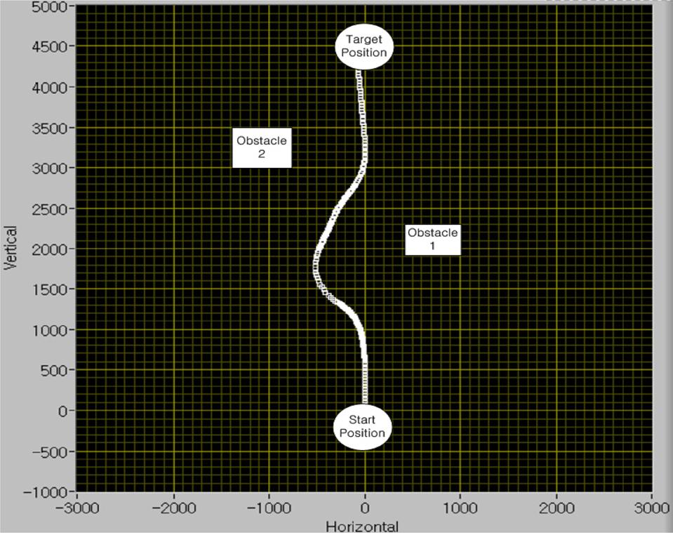
Table 8 presents the implementation results of each design. The buffer size of the full-LUT shown in Fig. 2 is (204+8469+847) × 4 bytes, while that of the shared LUT presented in Fig. 3 is 512 × 4 bytes. The processing clock cycle of each design in the table is the average computation of the clock cycles used in the avoidance operations during the navigation process from the starting position to the target position on the map. A fuzzy controller without LUT does not require a buffer for the LUT(s), but it does need 8 times as much time for the fuzzy operation compared to the full-LUT-based fuzzy controller. If all membership functions have LUTs, the operation time can be greatly reduced. However, this requires about 38Kbytes of LUT memory. The simulation result for the LUT sharing method showed that the fuzzy controller can operate well only with 5.34% of the full LUT's memory size. Although the controller requires about 1.5 times more operation time than the full-LUT-based design, the comparative reduction of the memory size is more advantageous for the system. In brief, the simulation results show that the LUT-based fuzzy controller greatly reduces the computational latency and obviously enhances the performance of a real-time obstacle avoidance system for an autonomous robot. Also, the LUT sharing method offers an approach that uses LUT-based architecture without the additional expense of added buffer memory. Figs. 9, 10, and 12 show the results, which were verified in the experiments based on a mobile robot (Pioneer P3-DX). Figs. 11 and 13 show the experiment processes in a cluttered environment for the result shown in Figs. 10 and 12, respectively.
Fuzzy controller implementation for obstacle avoidance with the LabVIEW application on a mobile robot (Pioneer P3-DX)
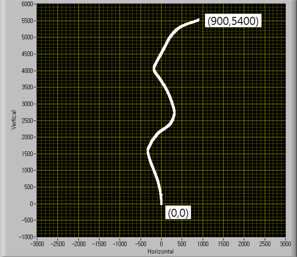
Experimental result for obstacle avoidance while navigating from the starting position (0, 0) to the target position (900, 5400) in a cluttered environment
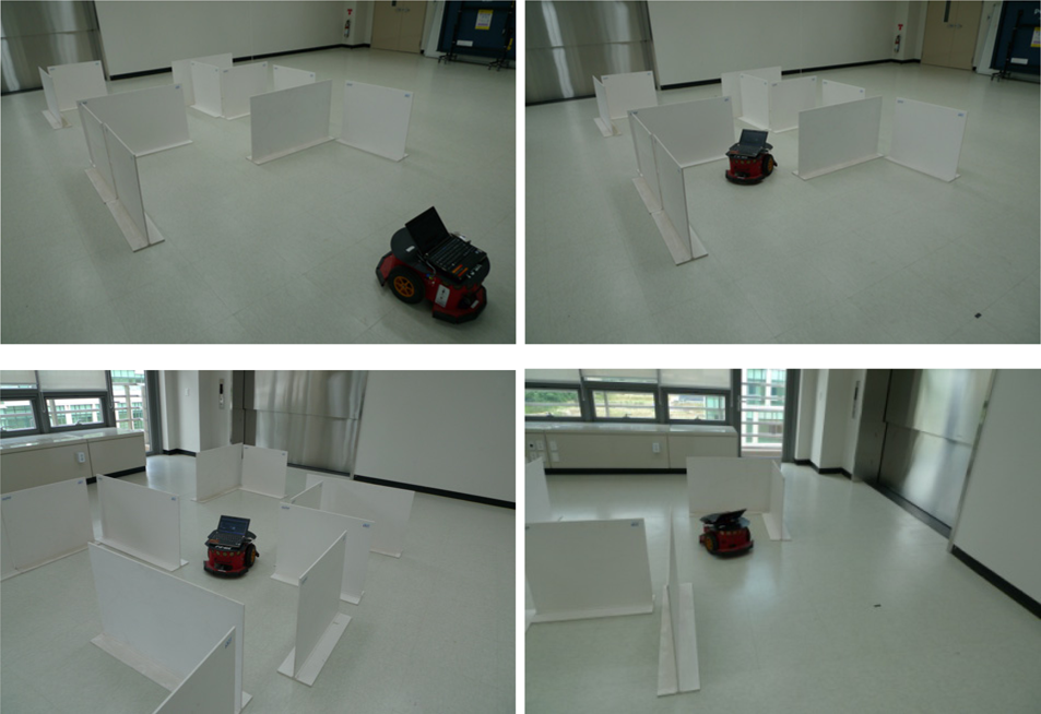
Experiment process in a cluttered environment for the result shown in Fig. 10
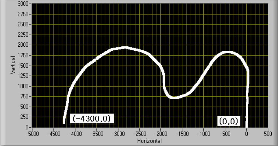
Experimental result of obstacle avoidance while navigating from the starting position (0, 0) to the target position (−4300, 0) in a cluttered environment

Experiment process in a cluttered environment for the result shown in Fig. 12
Buffer size and processing cycles of each fuzzy controller

This work sought to implement a real-time mobile robot system that uses relatively less power. To perform faster operations in real-time systems, using faster processors may be enough for the controller. However, there are limitations when designing a low-power system with only high-performance processors. It is necessary to reduce the operation clock frequency to lower the power consumption because a high clock frequency elevates the power consumption of the system. All of these factors make it clear that a reduction of the operational complexity is a better answer for both faster operation and lower power consumption.
We utilized LUT(s) to eliminate the calculation of the membership degrees, which can be complicated and reiterative. Thus, we designed a full-LUT-based fuzzy controller, with which the average operation time is reduced to 20% of the time required by the fuzzy controller without LUT(s). However, the full-LUT design requires the buffers to contain all of the membership function values. To reduce the buffer size, we attempted to share the LUT for the membership functions. While the simulation results showed that the proposed LUT sharing method requires 50% more operation cycles on average compared to the full-LUT-based design, the proposed method saves 94.5% of the original LUT buffer size. The results show that the LUT sharing method can be more worthwhile for real-time mobile robots because it is approximately 3.35 times faster than the use of a fuzzy controller without LUT(s).
In conclusion, this work can provide advantages to real-time obstacle avoidance systems for use in mobile robots because the LUT-based fuzzy controller design enables faster obstacle avoidance while the LUT sharing method provides compactness of the controller by reducing most of LUT buffers.
Footnotes
8.
This work was supported by the DGIST R&D Program of the Ministry of Education, Science, and Technology (MEST) of Korea (10-IT-03).