
Abstract
This paper presents algorithms implemented for positioning a wheeled robot on a production floor inside a factory by means of radio-frequency distance measurement and trilateration techniques. A set of radio-frequency transceivers located on the columns of the factory (anchors) create a grid with several triangular zones capable of measuring the line-of-sight distance between each anchor and the transceiver installed in the wheeled robot. After measuring only three of these distances (radii), an enhanced trilateration algorithm is applied to obtain X and Y coordinates in a Cartesian plane, i.e., the position of the robot on the factory floor. The embedded systems developed for the anchors and the robot are robust enough to establish communication, select the closest anchors for measuring radii, and identify in which of the grid zones the robot is located.
1. Introduction
Precise positioning and location has long been sought for autonomous and semi-autonomous vehicles. Since the advent of low-priced GNSS technologies (mostly integrated circuits for embedded systems), these technologies have been widely implemented. Even though the accuracy of commercial systems is still only to within a couple of metres, these tools have proven useful for most applications.
A drawback of this technology is its inability to work properly in indoor environments. In such situations, wheeled robots needing to know their position (on the plane they are moving in) usually implement dead-reckoning strategies based on the information obtained from an inertial navigation system. However, most such data, e.g., from odometers, gyroscopes, magnetometers and accelerometers, are prone to have noise and generate cumulative errors; furthermore, the position of a fixed initial point always needs to be known.
As the underlying technology for the Global Navigation Satellite System (GNSS) has proven so reliable, researchers have tried to mimic its functionality for indoor uses. However, this requires wireless transceivers that are fast enough to detect very small periods of time, allowing the system to accurately measure distances between the transceivers in the order of metres.
Until recently, the wireless technology capable of measuring the time-of-flight of a signal between two transceivers was bulky and/or expensive, and reproducing the geo-spatial positioning systems in a research or other indoor environment was therefore very difficult.
However, miniaturization and embedding of many of the enabling technologies have finally produced inexpensive commercial systems that can be used in developing a solution with the required characteristics. Such a system is presented in this paper. The algorithms and design are explained, as well as the performed experiments. The results are discussed and further development is proposed.
2. Related Work
Trilateration techniques for location purposes have been implemented in many different systems throughout the years. Some of them have been studied in depth, and the gained knowledge is applied directly in this work.
In 1990, Fang [1] proposed a simplification algorithm for trilateration, which makes a few interpretation assumptions and follows certain restrictions; this allowed for a simple solution and computation of the trilateration equations. This analytical solution was programmed in our system and the inaccuracies taken into account afterwards; this approach simplified the design and produced reliable results.
Two decades ago, wireless technology was neither as developed nor as cheap as it has become in recent years. This is one of the main reasons why distance measurement and location using wireless transceivers has just started to gain momentum. Furthermore, many of the first research systems required a lot of computational power; for example, in 2007, Mautz et al. [2] proposed a solution for locating nodes within a network. Five nodes were used and they communicated to a computational system in charge of minimizing errors using least-squares adjustment; however, this solution presented the inconvenience of centralization.
Towards achieving the computational requirements needed to solve the geometric algorithms, in 2008, Doukhnitch et al. [3] proposed a vector rotation method that proved more efficient than the existing methods. In 2013, Oguejiofor et al. [4] demonstrated a localization system with a wireless sensor network (WSN) that measured the distance between transceivers using the signal propagation and power law models from an RSSI (Received Signal Strength Indicator); however, this required complex computation and logarithmic functions, and resulted in a distance error higher than 70 cm.
High deviation is not uncommon for WSN systems. Therefore, several approaches have been implemented to reduce the measurement uncertainties. For instance, an improved weighted centroid algorithm was proposed by Bin et al. [5] in 2013; however, an optimized solution based on the Lemoine point that was presented in 2014 by Huang et al. [6], as well as a fuzzy optimization solution implemented by Jyoti et al. [7], gave better results.
Other AI programming techniques such as particle swarm optimization (PSO) were also studied by Ramesh et al. [8] in 2012, and many summaries and comparisons have been written regarding different localization methods. One such paper was presented in 2014 by Dyal et al. [9], for example.
More recently, the development of better hardware with high inherent accuracy (specifically the DW1000 chip from Decawave) has allowed programming of simpler algorithms where it may not be necessary to minimize measurement errors. This requires less computational power and enables implementation in a cheap embedded system. This is the approach presented in this paper.
3. Trilateration Algorithms
In simple terms, trilateration is a mathematical technique in which the location of a point in space is calculated using the distances from such a point to a series of known geometrical entities, e.g., a sphere or a circle.
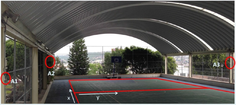
In a 3D space, if a point of interest lies on the surface of three intersecting spheres, then, knowing the centre positions of the spheres and their radii, it is possible to narrow the possible locations of the point to no more than two. Starting with the general case, the equation for a sphere centred at (xa, ya, za) is shown in (1):

Applying the analytical approach for the general case would require the equations for the three spheres to be formulated and solved for the three unknowns (x,y,z), i.e., the location of the intersection point; however, two assumptions can be made in order to simplify this problem:
In the case of an indoor location system, all the anchors (sphere centres) can be located at a fixed height on the same elevated plane, regarded as zero (z1=z2=z3=0).
The geometric algorithm can be simplified using Fang's method [1] so that one sphere centre is located at the origin of the elevated plane, another along the x-axis, and the third orthogonally to the previous two, effectively positioning three non-collinear points on a unique plane (Figure 1). Equations (2–4) depict these anchor coordinates:


Thus, the simplified system of equations, where the sphere radii become r1, r2, and r3, can be written as follows:


Simplifying equations (5–7) yields the following solutions:


As can be seen from equation (10), depending on the values of x and y, it is possible to obtain a negative root for the value of z, which in the embedded system produces an error. This drawback and the way it is approached is explained in the following sections.

Simplified trilateration in 2D
Equations (2–10) form the basis for locating a point in space, knowing the coordinates for the spheres’ centres and the measured radii from each centre to the point of interest. In a 3D space, such equations would yield two possible solutions, but based on the aforementioned simplifications it is possible to work in a 2D space and analytically obtain a single solution.
Since all the anchors are positioned at the same height (plane), which is parallel to the floor where the robot moves (Figure 2), it is safe to regard the z coordinate of the robot's location as a constant; in this particular case, there is no need to calculate it.

MATLAB® simulation of anchor positions, plane parallel to floor
The algorithms depicted so far allow for the location of a single point within the area covered by three transceivers (anchors). However, the transceivers give a precision of about 10 cm within a line-of-sight of approximately 30 metres; therefore, in order to create a system able to detect the robot's position inside a wide area, the installation of several anchors is required, thus generating a grid of triangular zones.
Each one of these zones is formed by arranging three transceivers, whose coordinates follow equations (2–4); the whole grid is created using regular triangular patterns in which two adjacent zones share two transceivers. Each zone has a different offset with respect to a global origin point.
The position of the robot is calculated by first obtaining the local coordinates inside the zone comprising the closest anchors to it and then adding that zone's offset to get the global position within the area of the factory floor (Figure 3).
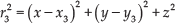
Anchor locations and zone delimitation for robot trajectory test
An example based on Figure 3 can be given to aid understanding of the procedure to establish anchor location and zone delimitation:
Zone A comprises anchors 12, 13, and 22, whose local coordinates (x a ,y a ,z a ) are A12(0,0,0), A13(10,0,0), and A22(5, 13, 0). For the depicted test, anchor 12 lies on the origin, so the global offset for that zone is Δ(0,0).
Zone B shares anchors 13 and 22, but these anchors now have a different set of local coordinates: A22(0,0,0), A23(10,0,0), and A13(5,-13,0). The offset for this zone's origin (anchor A22) is Δ(5,13).
For Zone C, the local origin would be at anchor A13 and the global offset Δ(10,0).
This locating approach is applied throughout the grid definition and can be reproduced for different zone sizes following the algorithm depicted in Figure 4. In the example from Figure 3, each anchor along the same row is separated by 10 metres; however, the chip range allows for separation of around 25–30 metres, depending on the environmental noise.

Zone detection and global positioning algorithm
4. Embedded System
As previously stated, the advantages of a system based on the GNSS technology make it desirable to implement for an indoor environment. The communication protocol can be replicated on an embedded scheme and simplified based on the following steps:
A receiver starts listening to the satellite broadcasts, which contain information on the precise time they were sent, the location of the satellite, and a global standardized time (with atomic clock precision).
The receiver measures the time-of-flight of the signal travelling from the satellite along the line-of-sight to the receiver, thereby calculating the distance between them. It performs the same measurement with at least three satellites.
Knowing the distances from the receiver to three of the satellites, and their orbital position, a trilateration algorithm can be applied to obtain the geo-spatial position of the receiver.
The system presented in this paper was developed using the wireless chip DW1000 from the Irish company Decawave, which allows precise distance measurement between two identical transceivers (however, each one is configured differently).
The idea behind the system was to apply the underlying principles used in GNSS technology by installing an elevated grid of anchors deliberately positioned to create triangular zones. Inside this grid, the robot's transceiver communicates with the three closest anchors. By measuring the time-of-flight of the signals and calculating the line-of-sight distances, it applies the trilateration algorithm enhanced for indoor applications in order to obtain the robot's position on a plane (factory floor).
After obtaining the local coordinates from the set of three anchors, the system installed on the robot verifies the zone and calculates the global position by analysing its offset in relation to the plane origin (Figure 4).
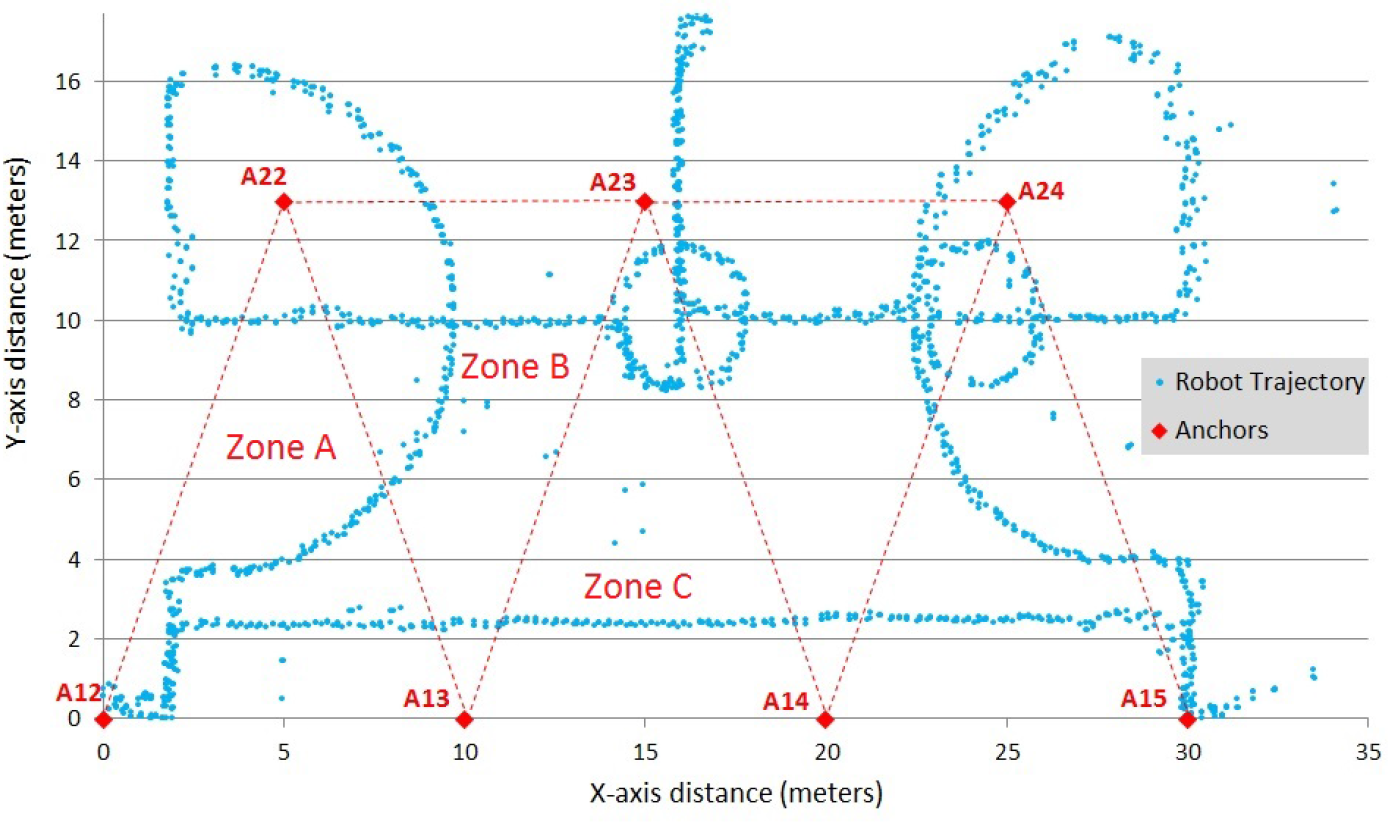
The hardware implemented for this system comprises two different electronic boards: one type for the anchors and another for the location and trilateration algorithms. The anchor boards consist of a microcontroller connected to the DW1000 chip along with the power supply and indicator LEDs (Figure 5), while the embedded system for the trilateration algorithms uses a Raspberry Pi B+ (RPi) microcomputer with a shield for connecting the DW1000 chip (Figure 6).
All the communication protocols and algorithms were programmed using C language in the microcontrollers and the RPi; the trilateration algorithms, zone lookup table for the coordinates, and control routines were saved in the Raspberry's solid-state memory.

Anchor embedded system
RPi embedded system with two chips and IMU
5. Experiments
The indoor positioning system described thus far was originally devised for locating a wheeled robot within the areas of a factory floor; however, the data presented were obtained through experiments in a controlled environment.
The grid of triangular zones for testing was relatively small compared to the factory dimensions; nevertheless, it was big enough for a proof of the concept of the system. The electronic boards for the anchors were enclosed for protection (Figure 5) and located over a planar surface following the pattern depicted in Figure 3.
With the seven anchors, five triangular zones were created, and the information for each one, including coordinates, global offset, and zone number, was stored in the solid-state memory of the RPi microcomputer.
The algorithm from Figure 4 was followed during the experiments:
The transceiver chip connected to the RPi communicated initially with all the anchors.
By identifying the three closest anchors, an algorithm selected the correct zone in which the system was located from the microcomputer memory.
The system measured the line-of-sight distance to each of the three anchors comprising the actual zone, and obtained the local XY coordinates using the trilateration algorithm.
Knowing the zone and its offset, the local coordinates were converted into global coordinates, taking as the global origin the position of anchor A12 (Figure 3).
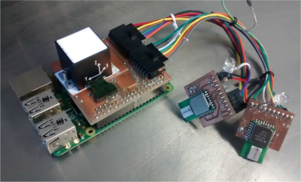
Anchor positions for court test
Several tests were performed in order to validate the algorithms and robustness of the system. One of these involved the positioning of three anchors inside a basketball court (Figure 7), and another involved seven anchors forming a grid with five zones, as depicted in Figure 3 and Figure 8.
A moving platform holding the transceiver shield connected to the RPi followed the paths painted on the court whilst saving the data for the X and Y coordinates as well as the zone in which it was located. Taking the position of anchor A12 as the origin, the global coordinates were calculated after measuring the local position inside each zone.
Figure 8 shows a graph of the data obtained directly from the measurements without any filtering. The colour of each point represents the zone identified directly from the system; as can be seen, the zone delimitation is acceptable and the measurement noise results are very low as well. Approximately 3% of the data was corrupted due to measurement or communication errors, but the ±10 cm accuracy remains within the specification.

Zone identification from embedded system
A subsequent test was conducted to verify the accuracy of the system, i.e., to validate that the measured distances were within the ±10 cm limits. For this test, 35 anchors were installed on columns inside a factory at 3.5 metres above the ground; the tag was then placed on a table 80 centimetres above the ground in an XY position below five of the anchors selected randomly. At each of the five positions, a series of 100 samples was taken and the deviation measured. Each sample consists of the line-of-sight distance between the tag and the three anchors, creating a triangular zone. Using the three distances, a pair of XY coordinates was obtained through the trilateration algorithms, thus obtaining 100 data pairs of XY coordinates for each sample. With these data sets, the standard deviation of each group of points was obtained.
A map of the anchors and the zones they create is depicted in Figure 9, whilst Table 1 shows the labels for each test and their selected anchors.
Anchors table for accuracy test

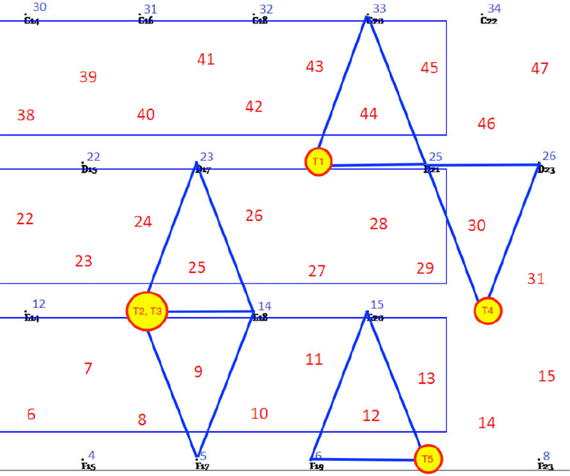
Map of anchors and zones inside factory
Figures 10, 11, 12, 13 and 14 depict the accuracy tests conducted on the five selected anchors, corresponding to the previous table. As can be noted, except for test 4, all the other measurements remain within the ±10 cm specified limit, with an overall average accuracy of ±4.09 cm.
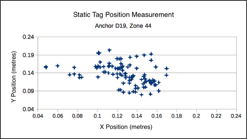
Test 1 XY position accuracy data. Test 1, Anchor D19, Zone 44: Standard Deviation X coordinate: 2.56 cm; Standard Deviation Y coordinate: 2.91 cm.

Test 2 XY position accuracy data. Test 2, Anchor E16, Zone 25: Standard Deviation X coordinate: 2.42 cm; Standard Deviation Y coordinate: 6.15 cm.

Test 3 XY position accuracy data. Test 3, Anchor E16, Zone 9: Standard Deviation X coordinate: 2.35 cm; Standard Deviation Y coordinate: 4.79 cm.
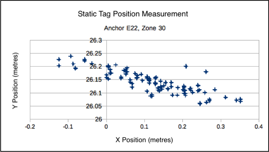
Test 4 XY position accuracy data. Test 4, Anchor E22, Zone 30: Standard Deviation X coordinate: 10.41 cm; Standard Deviation Y coordinate: 4.15 cm.

Test 5 XY position accuracy data. Test 5, Anchor F21, Zone 12; Standard Deviation X coordinate: 2.23 cm; Standard Deviation Y coordinate: 3.01 cm.
In 2013, Oguejiofor et al. [4] presented the experimental results of their RSSI-based location system where the position of a node was calculated from its distance to three fixed anchors (located at no more than 20 metres from the node). The estimated position was relatively accurate, remaining within 74 centimetres of the actual location of the node. But comparing that error to our average of ±4.09 cm, it is clear that the solution proposed here presents a significant accuracy increase.
Data filtering
From the first tests, it was observed that due to electromagnetic noise and/or physical obstacles, the line-of-sight measurements varied considerably, resulting in highly deviated XY coordinates. To overcome this, a simple filter was designed. This filtering algorithm took the trilateration calculation for the Z coordinate (equation 10) and compared it with the actual Z position of the tag, which remained a fixed value due to the level floor. Thus, if the difference between the real value and the calculated one was greater than 20%, this data set was disregarded and the previous one used instead.
6. Conclusions
This paper presents a robust positioning solution involving several areas of development and expertise. A lot of work was invested in the design and programming of the trilateration algorithms, as well as in the design and manufacture of the embedded systems.
The DW1000 chips are state-of-the-art devices that present many challenges to make them work seamlessly. However, once that learning curve was overcome, their functionality and advantages were fully exploited.
Although this research was based on several examples for positioning devices using trilateration, the real contribution of the project is in revamping such techniques by applying the zone selection algorithms, effectively increasing the final reach and scope.
It is clear that precise indoor positioning has a long way to go, but further developments seem inevitable and present very interesting implications.
7. Future Work
In addition to the actual system presented here, several improvements are being developed to create a more robust solution. The implementation of an Inertial Measurement Unit (IMU) to obtain the orientation and direction of the movement, as well as enhancements of the algorithms will allow for more precise location and data analysis for automatic navigation control.
Other techniques, such as Kalman filtering and centroid calculation, also feature in on-going research. A second prototype implementing a DV-HOP strategy, as proposed by Xu et al. [10], will allow for a more robust system. The miniaturization and embedding of this solution for different platforms will eventually provide the desired outcome.
Footnotes
8. Acknowledgements
The authors want to thank the Engineering and Industrial Development Center (CIDESI) for their support in this project.